
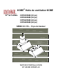
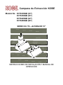
KOBE Brand Range Hood
Model No. CH7630SQB (30)
CH7636SQB (36)
CH7642SQB (42)
CH7648SQB (48)
CH-176 SERIES – 10 HEIGHT
INSTALLATION INSTRUCTIONS
AND OPERATION MANUAL

- READ AND SAVE THESE INSTRUCTIONS -
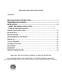
CONTENTS
IMPORTANT SAFETY INSTRUCTIONS .........................................................................1
COMPONENTS OF PACKAGE .......................................................................................3
INSTALLATION ...............................................................................................................4
UNDER THE CAB INET INSTALLATION ........................................................... 6
STAND ALONE INSTALLATION ....................................................................... 9
OPERATION INSTRUCTIONS ......................................................................................13
MAINTENANCE .............................................................................................................15
SPECIFICATIONS..........................................................................................................17
MEASUREMENTS & DIAGRAMS .................................................................................18
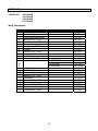
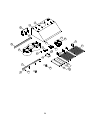
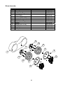
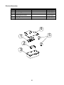
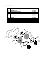
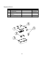
PARTS LIST ..................................................................................................................23
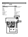
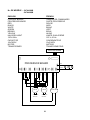
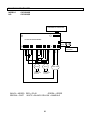
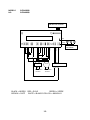
CIRCUIT DIAGRAM .......................................................................................................27
TROUBLE SHOOTING ..................................................................................................29
DISCLAIMER .................................................................................................................30
WARRANTY ..................................................................................................................31
PRODUCT REGISTRATION ..........................................................................................33
- READ ALL INSTRUCTIONS CAREFULLY BEFORE STARTING -
ALL WIRING MUST BE DONE BY A PROFESSIONAL AND IN
ACCORDANCE WITH NATIONAL AND LOCAL ELECTRICAL CODES

1
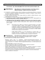
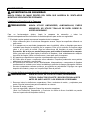
IMPORTANT SAFETY INSTRUCTIONS
- PLEASE READ THIS SECTION CAREFULLY BEFORE INSTALLATION -
:
TO REDUCE THE RISK OF FIRE, ELECTRIC SHOCK OR PERSONAL
INJURY, OBSERVE THE FOLLOWING:
1) Installation and electrical wiring must be done by qualified professionals and in accordance with all
applicable codes and standards, including fire-rated construction.
2) When cutting or drilling into wall or ceiling, be careful not to damage electrical wiring or other hidden
utilities.
3) Ducted fans must be vented to the outside.
a) Before servicing or cleaning unit, open the light panel and SWITCH POWER OFF AT SERVICE
PANEL.
b) Clean all grease laden surfaces frequently. To reduce the risk of fire and to disperse air
properly, make sure to vent air outside. DO NOT vent exhaust air into wall spaces, attics, crawl
spaces or garages.
NOTE - This warranty is invalid without an authorized agent’s receipt or if unit is
damaged due to misuse, poor installation, improper use, mistreatment,
negligence or any other circumstances beyond the control of KOBE RANGE
HOODS authorized agents. Any repair carried out without the supervision of
KOBE RANGE HOODS authorized agents will automatically void the warranty.
- KOBE RANGE HOODS will not be held responsible for any damages to
personal property or real estate or any bodily injuries whether caused directly or
indirectly by the range hood.
: TO REDUCE THE RISK OF PERSONAL INJURY IN THE EVENT OF A
RANGE TOP GREASE FIRE:
- Keep all fan, baffle/spacer/filter/oil tunnel/oil container and grease-laden surfaces clean. Grease
should not be allowed to accumulate on fan, baffle/spacer/filter/oil tunnel/oil container.
- Always turn hood ON when cooking.
- Use high settings on cooking range ONLY when necessary.
- Do not leave cooking range unattended when cooking.
- Always use cookware and utensils appropriate for the type and amount of food prepared.
- Use this unit only in the manner intended by the manufacturer.
- Before servicing, switch power off at service panel and lock service panel (if possible) to prevent
power from switching on accidentally.
- Clean ventilating fan frequently.

2
What to Do In The Event Of a Range Top Grease Fire
- SMOTHER FLAMES with a tight fitting lid, cookie sheet, or metal tray, and then turn off the burner.
KEEP FLAMMABLE OR COMBUSTIBLE MATERIAL AWAY FROM FLAMES. If the flames do not
go out immediately, EVACUATE THE AREA AND CALL THE FIRE DEPARTMENT or 911.
- NEVER PICK UP A BURNING PAN – You May Get Burned.
- DO NOT USE WATER, including wet dishcloths or towels – a violent steam blast will result.
- Use an extinguisher ONLY if:
a) You have a Class A, B, C extinguisher and know how to operate it.
b) The fire is small and contained in the area where it started.
c) The fire department has been called.
d) You can fight the fire with your back to an exit.
What to Do If You Smell Gas
-
Extinguish any open flame.
-
Do not try to turn on the lights or any type of appliance.
-
Open all doors and windows to disperse the gas. If you still smell gas, call the Gas Company and
Fire Department right away.
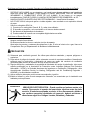
1) For general ventilation use only. Do not use to exhaust hazardous or explosive materials and
vapors.
2) To reduce the risk of fire, use only metal ductwork. Sufficient air is needed for proper combustion
and exhausting of gases through the flue (chimney) to prevent back drafting.
3) Follow the heating equipment manufacturer’s guideline and safety standards such as those
published by the National Fire Protection Association (NFPA), and the American Society for
Heating, Refrigeration and Air Conditioning Engineers (ASHRAE), and code authorities.
4) Activating any switch on may cause ignition or an explosion.
5) Due to the size and weight of this hood, two people installation is recommended.
ELECTRICAL SHOCK HAZARD
–
Can result in serious injury or death.
Disconnect appliance from electric power before servicing. If
equipped, the fluorescent light bulb contains small amounts of
mercury, which must be recycled or disposed of according to Local,
State, and Federal Codes.

3
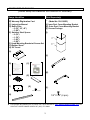
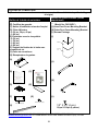
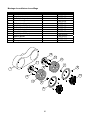
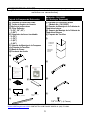
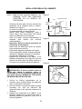
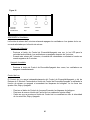
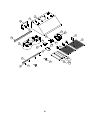
COMPONENTS OF PACKAGE
(Must keep all material for returns or refunds)
Range Hood Box
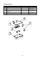
Duct Cover Box
– Model No.: CH1120DC
(Sold Separately)
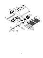
{A} KOBE Range Hood
{B} Warranty Registration Card
{C} Instruction Manual
{D} Baffle Filter
-- 2 (30, 36, 42)
-- 3 (48)
{E} Stainless Steel Spacer
-- 0 (30)
-- 1 (36)
-- 3 (42)
-- 2 (48)
{F} Hood-Mounting Bracket w/ Screws Set
{G} Rubber Stand
{H} Oil Tunnel
{A}
{B} {C}
{D} {E}
{F} {G}
{H}
{I} KOBE Duct Cove
r
(Model No. CH1120DC)
{J} Inner Duct Cover-Mounting Bracket
{K} Outer Duct Cover-Mounting Bracket
{L} Screws Package
{I}
{J}
{K}
{L}
FOR MORE INFORMATION, PLEASE VISIT OUR WEBSITE www.KOBERANGEHOODS.com OR
CONTACT KOBE RANGE HOODS AT (626) 775-8880.
3/16" X 1/2" (8 pcs)
Rubber Stand (2 pcs)
Inner Duct
Cover
Outer Duct
Cover
1/8" X 3/8" (4 pcs)

4
INSTALLATION
PLEASE READ ENTIRE INSTRUCTIONS BEFORE PROCEEDING
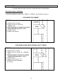
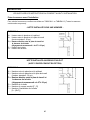
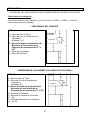
Calculation before Installation
To calculate installation, please refer to TABLE 1 or TABLE 2. (All calculation in inches.)
- FOR UNDER THE CABINET -
TABLE 1
A = Height of Floor to Ceiling
B = Height of Floor to Counter Top
(Standard: 36)
C = Preferred Height of Counter Top to Hood
Bottom (Recommended 27 to 30)
D = Height of Hood
E = Height of the Cabinet
- FOR STAND ALONE (WITH OPTIONAL DUCT COVER) -
TABLE 2
A = Height of Floor to Ceiling
B = Height of Floor to Counter Top (Standard:
36”)
C = Preferred Height of Counter Top to Hood
Bottom (Recommended 27 to 30)
D = Height of Hood
E = Height of Duct Cover [F – D]
F = Height of the Hood Installation
[A – (B+C)]

5
HOOD MAY HAVE VERY SHARP EDGES; PLEASE WEAR PROTECTIVE GLOVES IF
REMOVING ANY PARTS FOR INSTALLING, CLEANING OR SERVICING.
NOTE: BE CAREFUL WHEN USING ELECTRICAL SCREWDRIVER, DAMAGE TO THE HOOD
MAY OCCUR.
Installation Contents
UNDER THE CABINET INSTALLATION ........................................................................6
P
REPARATION BEFORE
I
NSTALLATION
............................................................................ 6
H
OOD
I
NSTALLATION
...................................................................................................... 6
D
UCTWORK
I
NSTALLATION
............................................................................................. 7
W
IRING TO
P
OWER
S
UPPLY
............................................................................................ 7
A
CCESSORIES
............................................................................................................... 8
F
INAL
A
SSEMBLY
........................................................................................................... 8
STAND ALONE INSTALLATION .....................................................................................9
P
REPARATION BEFORE
I
NSTALLATION
............................................................................ 9
H
OOD
P
REPARATION BEFORE
I
NSTALLATION
.................................................................. 9
H
OOD
I
NSTALLATION
...................................................................................................... 9
W
IRING TO
P
OWER
S
UPPLY
.......................................................................................... 10
D
UCT
C
OVER
I
NSTALLATION
......................................................................................... 11
A
CCESSORIES
............................................................................................................. 11
F
INAL
A
SSEMBLY
......................................................................................................... 12

6
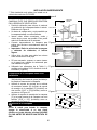
UNDER THE CABINET INSTALLATION
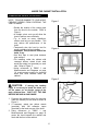
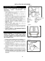
Preparation before Installation
NOTE: TO AVOID DAMAGE TO YOUR HOOD,
PREVENT DEBRIS FROM ENTERING THE
VENT OPENING.
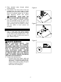
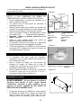
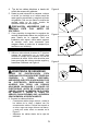
Decide the location of the venting pipe
from the hood to the outside. Refer to
Figure 1.
A straight, short vent run will allow the
hood to perform more efficiently.
Try to avoid as many transitions,
elbows, and long run as possible. This
may reduce the performance of the
hood.
Temporarily wire the hood to test for
proper operation before installing.
Important: Peel protective film off the
hood, if any.
Use duct tape to seal joints between
pipe sections.
For installing under the cabinet with
recessed bottom, attach 4-inch wide
wood filler strips (not provided) on each
side. Refer to Figure 2.
Using references in TABLE 1 and
Measurements and Diagrams on page
18, create access opening for electrical
wires and hood exhaust under the
cabinet.
Hood Installation
CAUTION
: If moving the cooking
range is necessary to install the hood, turn
off the power on an electric range at the
main electrical box. SHUT OFF THE GAS
BEFORE MOVING A GAS RANGE.
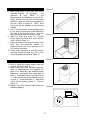
1. Puncture the knockout holes (for mounting
under the cabinet) on the hood as shown in
Figure 3.
2. If necessary, attach two rubber stands
(provided) with 3M adhesive tapes
(provided) to the back corners of the hood.
3. Using references in TABLE 1 and
Measurements and Diagrams on page 18
center the hood beneath the cabinet and
flush with the front of the cabinet.
Figure 1
Figure 2
.
Figure 3

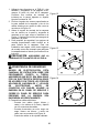
7
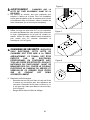
4. Draw electrical wires through cabinet
access opening.
5. From inside of the hood, place screw (not
provided) into the exact center of each
knockout hole and secure to cabinet bottom.
Once all mounting screws are in place,
finish tightening screws until secure.
CAUTION
: MAKE SURE THE
HOOD IS SECURE BEFORE RELEASING.
6. For safety purpose, pre-drilled mounting
holes are provided through the back of the
hood. For a more secure installation, use as
many mounting holes as needed to secure
from the inside of hood (screws not
provided).
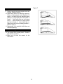
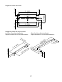
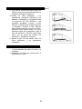
Ductwork Installation
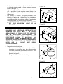
7. Use 7 round steel pipe (follow building
codes in your area) to connect the exhaust
on the hood to the ductwork above. Use
duct tape to make all joints secure and air
tight. Refer to Figure 4.
Wiring to Power Supply
RISK OF ELECTRICAL SHOCK. THIS
RANGE HOOD MUST BE PROPERLY
GROUNDED. MAKE SURE THIS IS DONE BY
QUALIFIED ELECTRICIAN IN ACCORDANCE
WITH ALL APPLICABLE NATIONAL AND
LOCAL ELECTRICAL CODES. BEFORE
CONNECTING WIRES, SWITCH POWER OFF
AT SERVICE PANEL AND LOCK SERVICE
PANEL TO PREVENT POWER FROM BEING
SWITCHED ON ACCIDENTALLY.
8. Connect the electrical wires.
- Connect three wires (black, white and
green) to house wires and cap with wire
connectors. Connect according to color:
black to black, white to white, and green
to green as shown in Figure 5.
- Store wires in the wiring box.
Figure 4
Figure 5
Figure 6

8
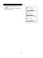
Accessories
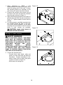
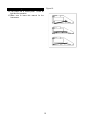
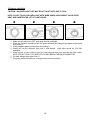
9. Drop oil tunnel into recess support near rear
of hood. Refer to Figure 6.
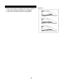
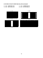
10. Install baffle filters and stainless spacer(s).
Refer to Measurements and Diagrams on
page 22 for baffle filter and stainless spacer
placement. Angle baffle filter toward back of
hood c. Push baffle filter up until almost
level d. Slide forward into recess behind
the front of hood e. Lower baffle filter f.
Slide back until it fits into resting position g .
Refer to Figure 7.
11. Repeat step 10 to install all baffle filters and
stainless spacer(s).
Final Assembly
12. Turn power ON in control panel. Check all
light and fan operation.
13. Make sure to leave this manual for the
homeowner.
Figure 7

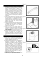
9
STAND ALONE INSTALLATION
*** This installation only applies if installing with
the CH1120DC duct cover.
Preparation before Installation
NOTE: TO AVOID DAMAGE TO YOUR HOOD,
PREVENT DEBRIS FROM ENTERING THE
VENT OPENING.
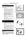
Decide the location of the venting pipe
from the hood to the outside. (Figure 8)
A straight, short vent run will allow the
hood to perform more efficiently.
Try to avoid as many transitions, elbows,
and long run as possible. This may
reduce the performance of the hood.
Temporarily wire the hood to test for
proper operation before installing.
Important: Peel protective film off the
hood and duct covers, if any.
Use duct tape to seal joints between pipe
sections.
If necessary, prepare back wall frame with
cross framing lumber for secure
installation.
Using references in TABLE 2 and
measurements on pages 19-21, determine
the level of the lumber. (Figure 9)
Hood Preparation before
Installation
If necessary, attach two rubber stands
(provided) with 3M adhesive tapes
(provided) to the back corners of the
hood.
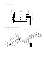
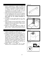
Attach the outer duct cover-mounting
bracket {K} (provided) to the hood-
mounting bracket {F} (provided) with two
(3/16 x 1/2) screws (provided) as shown
in Figure 10.
Attach the hood-mounting bracket {F} to
the back of the hood with six (3/16 x 1/2)
screws (provided) as shown In Figure 11.
Hood Installation
CAUTION
: If moving the cooking range
to install the hood is necessary, turn off the
power on an electric range at the main
electrical box. SHUT OFF THE GAS BEFORE
MOVING A GAS RANGE.
Figure 8
Figure 9
Figure 10
Figure 11

10
1. Using references in TABLE 1 and
Measurements and Diagrams on pages 19-21,
mark the leveling point of the hood. Position
two mounting screws (not provided) on the
wall, leaving 1/8 space away from the wall.
2. Puncture the knockout wire access hole at
the back of the hood and draw the electrical
wires through as shown in Figure 12.
3. Align hood-mounting bracket to the screws on
the wall and hook hood into place as shown in
Figure 13. Tighten screws to secure hood to
the wall.
4. For safety purpose, pre-drilled mounting holes
are provided through the back of the hood.
For a more secure installation, use as many
mounting holes as needed to secure from the
inside of hood (screws not provided).
CAUTION
: MAKE SURE HOOD IS
SECURE BEFORE RELEASING.
Wiring to Power Supply
RISK OF ELECTRICAL SHOCK. THIS RANGE
HOOD MUST BE PROPERLY GROUNDED.
MAKE SURE THIS IS DONE BY QUALIFIED
ELECTRICIAN IN ACCORDANCE WITH ALL
APPLICABLE NATIONAL AND LOCAL
ELECTRICAL CODES. BEFORE
CONNECTING WIRES, SWITCH POWER OFF
AT SERVICE PANEL AND LOCK SERVICE
PANEL TO PREVENT POWER FROM BEING
SWITCHED ON ACCIDENTALLY.
5. Connect the electrical wires.
- Connect three wires (black, white and
green) to house wires and cap with wire
connectors. Connect according to color:
black to black, white to white, and green
to green as shown on Figure 14.
- Store wires in the wiring box.
Figure 12
Figure 13
Figure 14
WALL

11
Duct Cover Installation
6. Mark the position of the inner duct cover-
mounting bracket {J} (provided). Use
reference E from TABLE 2 and
Measurements and Diagrams on page 20-21.
Attach and secure inner duct cover-mounting
bracket {J} with two screws (not provided) to
the wall. Refer to Figure 15. NOTE: Inner
duct cover will be attached to the mounting
bracket.
7. Use 7 round steel pipe (follow building codes
in your area) to connect the round exhaust on
the hood to the ductwork above. Use duct
tape to make all joints secure and air tight.
8. Slide the inner duct cover up 2 inches
before sliding the entire duct cover onto the
hood. Refer to Figure 16.
9. Adjust the height of the inner duct cover to the
inner duct cover-mounting bracket {J}.
Secure the inner duct cover with two (1/8 x
3/8) screws (provided).
10. Fasten outer duct cover to outer duct cover-
mounting bracket {K} with two (1/8 x 3/8)
screws (provided) as shown in Figure 17.
Accessories
11. Drop oil tunnel into recess support near rear
of hood. Refer to Figure 18.
12. Install baffle filters and stainless spacer(s).
Refer to Measurements and Diagrams on
page 22 for baffle filter and stainless spacer
placement. Angle baffle filter toward back of
hood c. Push baffle filter up until almost level
d. Slide forward into recess behind the front
of hood e. Lower baffle filter f. Slide back
until it fits into resting position g. Refer to
Figure 19.
13. Repeat step 12 to install all baffle filters and
stainless spacer(s).
Figure 15
Figure 16
Figure 17
Figure 18

12
Final Assembly
14. Turn power ON in control panel. Check all
light and fan operation.
15. Make sure to leave this manual for the
homeowner.
Figure 19

13
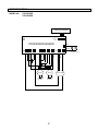
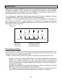
OPERATION INSTRUCTIONS
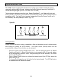
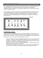
This KOBE hood is equipped with six electronic controls, two powerful centrifugal squirrel
cages with stainless steel oil tunnel, stainless steel baffle filters and spacer(s), and bright 12-
volt 20-watt halogen lights (2 for 30 & 36 and 3 for 42 & 48).
The six electronic buttons control the Light, Speed (QuietMode™, Low, Medium & High) and
Power (On/Off). The Power Control offers a 10-second delay startup, 3-minute delay shutoff or
immediate shutoff. The Light Control operates independently from the Power Control and is
not affected by the delay startup or shutoff. (Fig. 20)
Figure 20
4
Light control
Speed control
Power control
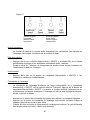
Turning Fan ON:
Always turn fans on before cooking to establish air flow and allow fans to run for a few minutes
after cooking for cleaner air in the kitchen. The Power Control (On/Off) button must be
pressed before a Speed Control button can be activated.
- Press the Power Control (On/Off) button once. The four LED lights above the Speed
Controls will flash, if a Speed Control button is not pressed within 10 seconds, power
will be automatically released. Note: The light setting will not be affected by the Power
Control (On/Off) button.
- Press a Speed Control button to activate the desired speed (the LED light above the
button will light up).
- To change the fan speed, press the button for the desired speed. The LED light above
the speed button will indicate fan speed.

14
Figure 21
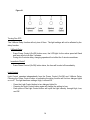
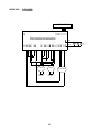
Turning Fan OFF:
The 3-Minute Delay function will only turn off fans. The light settings will not be affected by the
delay function.
3-Minute Delay
- Press Power Control (On/Off) button once, the LED light for the active speed will flash
and fans will shut off after 3 minutes.
- During this 3-minute delay, changing speeds will not affect the 3 minute countdown.
Immediate Shutoff
- Press Power Control (On/Off) button twice, the fans will be shut off immediately.
Light Control:
Light Control operates independently from the Power Control (On/Off) and 3-Minute Delay.
Pressing the Power Control button or activating the delay function will not turn halogen lights
on or off. The light has three settings: High, Low and Off.
- Press the Light Control button to turn halogen lights On.
- Pressing the Light Control button again will change the setting to Low.
- Each press of the Light Control button will cycle the light intensity through High, Low,
and Off.

15
MAINTENANCE
NEVER PUT YOUR HAND INTO AREA HOUSING THE FAN WHILE THE FAN IS
OPERATING.
Cleaning Hood Surface
: NEVER USE ABRASIVE CLEANERS, PADS, OR CLOTHS. DO NOT
USE PAPER TOWEL ON STAINLESS STEEL.
For optimal operation, clean range hood and all baffle/spacer/filter/oil tunnel/oil container regularly.
*** Regular care will help preserve the appearance of the hood.
1. Use only mild soap or detergent solutions. Dry surfaces using soft cloth.
2. If hood looks splotchy (stainless steel hood), use a stainless steel cleaner to clean the surface
of the hood. Avoid getting cleaning solution onto or into the control panel. Follow directions of
the stainless steel cleaner. Caution: Do not leave on too long as this may cause damage to
hood finish. Use soft towel to wipe off the cleaning solution, gently rub off any stubborn spots.
Use dry soft towel to dry the hood.
3. DO NOT allow deposits to accumulate or remain on the hood.
4. DO NOT use ordinary steel wool or steel brushes. Small bits of steel may adhere to the surface
and cause rusting.
5. DO NOT allow salt solutions, disinfectants, bleaches, or cleaning compounds to remain in
contact with stainless steel for extended periods. Many of these compounds contain chemicals,
which may be harmful. Rinse with water after exposure and wipe dry with a clean lint free cloth.
To Clean Baffle, Spacer, Filter, Oil Tunnel and Oil Container
CAUTION
: DRAIN OIL FROM BAFFLES, SPACER(S), FILTERS, OIL TUNNEL(S) AND OIL
CONTAINERS BEFORE OIL AND RESIDUE CAN OVERFLOW.
1. Remove all baffles, spacer(s), filters, oil tunnel(s), and oil containers. Follow directions for
installation in reverse.
2. Discard oil and residue.
3. Wash with warm soapy water. Dry thoroughly before replacing.
(Note: Stainless Steel Baffles, Spacer(s) & Oil Tunnel are top rack dishwasher safe.)

16
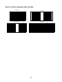
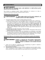
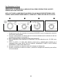
To Replace Light Bulb
CAUTION: HALOGEN LIGHT UNIT MAY BE HOT! WAIT UNTIL UNIT IS COOL.
NOTE: DO NOT TOUCH HALOGEN LIGHT WITH BARE HANDS, WHICH MIGHT CAUSE OVER
HEAT AND SHORTEN THE LIFT OF LIGHT BULBS.
c
cc
c
d
dd
d
e
ee
e
f
ff
f
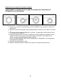
1. Make sure all controls are OFF, and range hood is unplugged.
2. Place the flat-head screwdriver into the groove between the halogen light glass covering and
the housing c.
3. Gently separate glass covering from the housing d.
4. Gently pull out the defective light bulb e and discard. Light bulbs should be 12V 20W
maximum.
5. Wear a glove or use a cloth to hold the new light bulb and push securely into light socket.
NOTE: DO NOT PUSH TOO HARD OR YOU MAY BREAK THE BULB CONNECTOR.
6. Put back halogen light glass cover f.
7. Plug back power cord and turn on range hood to test for operation.

17
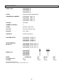
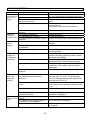
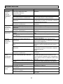
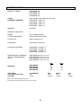
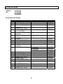
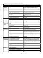
SPECIFICATIONS
MODEL / SIZE
CH7630SQB / 30
CH7636SQB / 36
CH7642SQB / 42
CH7648SQB / 48
COLO
R
Commercial Grade Stainless Steel
CONSUMPTION / AMPERE
CH7630SQB – 300W / 3A
CH7636SQB – 300W / 3A
CH7642SQB – 300W / 3A
CH7648SQB – 300W / 3A
VOLTAGE
120V 60Hz
NUMBER OF MOTORS
2
DESIGN
Seamless / Satin Finish
FAN TYPE
Twin Vertical Squirrel Cage
EXHAUST
Top 7 Round
CONTROLS
Six Electronic Buttons
HALOGEN LIGHTS
CH7630SQB - 12V 20W x 2
CH7636SQB - 12V 20W x 2
CH7642SQB - 12V 20W x 3
CH7648SQB - 12V 20W x 3
HOOD DIMENSION
(W x D x H)
(CH7630SQB) 29-3/4 x 22 x 10
(CH7636SQB) 35-3/4 x 22 x 10
(CH7642SQB) 41-3/4 x 22 x 10
(CH7648SQB) 47-3/4 x 22 x 10
WEIGHT (lbs)
Net
Gross
(CH7630SQB)
49 58
(CH7636SQB)
53 64
(CH7642SQB)
62 75
(CH7648SQB)
69 84
SPEED
QuietMode¥
¥¥
¥
Low Medium High
Air Capacity (cfm)*
385 460 560 700
Sone(dB)
1.2(42) 3.0(56) 4.0(60) 5.0(64)
*In House Test Static Pressure “0”.
**Specifications information is subject to change without notice.

18
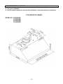
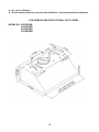
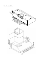
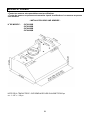
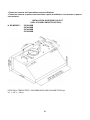
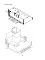
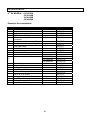
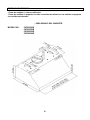
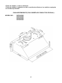
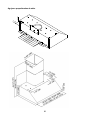
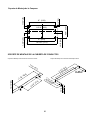
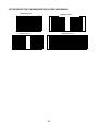
MEASUREMENTS & DIAGRAMS
All ( ) are in millimeter.
All inch measurements are converted from millimeters. Inch measurements are estimated.
- FOR UNDER THE CABINET -
MODEL NO: CH7630SQB
CH7636SQB
CH7642SQB
CH7648SQB
La page est en cours de chargement...
La page est en cours de chargement...
La page est en cours de chargement...
La page est en cours de chargement...
La page est en cours de chargement...
La page est en cours de chargement...
La page est en cours de chargement...
La page est en cours de chargement...
La page est en cours de chargement...
La page est en cours de chargement...
La page est en cours de chargement...
La page est en cours de chargement...
La page est en cours de chargement...
La page est en cours de chargement...
La page est en cours de chargement...
La page est en cours de chargement...
La page est en cours de chargement...
La page est en cours de chargement...
La page est en cours de chargement...
La page est en cours de chargement...
La page est en cours de chargement...
La page est en cours de chargement...
La page est en cours de chargement...
La page est en cours de chargement...
La page est en cours de chargement...
La page est en cours de chargement...
La page est en cours de chargement...
La page est en cours de chargement...
La page est en cours de chargement...
La page est en cours de chargement...
La page est en cours de chargement...
La page est en cours de chargement...
La page est en cours de chargement...
La page est en cours de chargement...
La page est en cours de chargement...
La page est en cours de chargement...
La page est en cours de chargement...
La page est en cours de chargement...
La page est en cours de chargement...
La page est en cours de chargement...
La page est en cours de chargement...
La page est en cours de chargement...
La page est en cours de chargement...
La page est en cours de chargement...
La page est en cours de chargement...
La page est en cours de chargement...
La page est en cours de chargement...
La page est en cours de chargement...
La page est en cours de chargement...
La page est en cours de chargement...
La page est en cours de chargement...
La page est en cours de chargement...
La page est en cours de chargement...
La page est en cours de chargement...
La page est en cours de chargement...
La page est en cours de chargement...
La page est en cours de chargement...
La page est en cours de chargement...
La page est en cours de chargement...
La page est en cours de chargement...
La page est en cours de chargement...
La page est en cours de chargement...
La page est en cours de chargement...
La page est en cours de chargement...
La page est en cours de chargement...
La page est en cours de chargement...
La page est en cours de chargement...
La page est en cours de chargement...
La page est en cours de chargement...
La page est en cours de chargement...
La page est en cours de chargement...
La page est en cours de chargement...
La page est en cours de chargement...
La page est en cours de chargement...
La page est en cours de chargement...
La page est en cours de chargement...
La page est en cours de chargement...
La page est en cours de chargement...
La page est en cours de chargement...
La page est en cours de chargement...
La page est en cours de chargement...
La page est en cours de chargement...
La page est en cours de chargement...
La page est en cours de chargement...
La page est en cours de chargement...
La page est en cours de chargement...
La page est en cours de chargement...
La page est en cours de chargement...
La page est en cours de chargement...
-
 1
1
-
 2
2
-
 3
3
-
 4
4
-
 5
5
-
 6
6
-
 7
7
-
 8
8
-
 9
9
-
 10
10
-
 11
11
-
 12
12
-
 13
13
-
 14
14
-
 15
15
-
 16
16
-
 17
17
-
 18
18
-
 19
19
-
 20
20
-
 21
21
-
 22
22
-
 23
23
-
 24
24
-
 25
25
-
 26
26
-
 27
27
-
 28
28
-
 29
29
-
 30
30
-
 31
31
-
 32
32
-
 33
33
-
 34
34
-
 35
35
-
 36
36
-
 37
37
-
 38
38
-
 39
39
-
 40
40
-
 41
41
-
 42
42
-
 43
43
-
 44
44
-
 45
45
-
 46
46
-
 47
47
-
 48
48
-
 49
49
-
 50
50
-
 51
51
-
 52
52
-
 53
53
-
 54
54
-
 55
55
-
 56
56
-
 57
57
-
 58
58
-
 59
59
-
 60
60
-
 61
61
-
 62
62
-
 63
63
-
 64
64
-
 65
65
-
 66
66
-
 67
67
-
 68
68
-
 69
69
-
 70
70
-
 71
71
-
 72
72
-
 73
73
-
 74
74
-
 75
75
-
 76
76
-
 77
77
-
 78
78
-
 79
79
-
 80
80
-
 81
81
-
 82
82
-
 83
83
-
 84
84
-
 85
85
-
 86
86
-
 87
87
-
 88
88
-
 89
89
-
 90
90
-
 91
91
-
 92
92
-
 93
93
-
 94
94
-
 95
95
-
 96
96
-
 97
97
-
 98
98
-
 99
99
-
 100
100
-
 101
101
-
 102
102
-
 103
103
-
 104
104
-
 105
105
-
 106
106
-
 107
107
-
 108
108
-
 109
109


Kobe CH7630SQB Manuel utilisateur
- Catégorie
- Hottes
- Taper
- Manuel utilisateur
dans d''autres langues
- English: Kobe CH7630SQB User manual
- español: Kobe CH7630SQB Manual de usuario
Documents connexes
-
Kobe Range Hoods CH2736SQB Manuel utilisateur
-
Kobe Range Hoods CH7742SQB Manuel utilisateur
-
Kobe CH2230SQ Manual-PDF
-
-
Kobe Range Hoods RA-094 Serie Manuel utilisateur
-
-
-
-
Autres documents
-
-
-
-
-
-
 HUUM Air Tunnel for HUUM Electric Sauna Heater Mode d'emploi
-
-
 Soler & Palau TD-315 Installation Instructions Manual
-
Monogram ZV750SPSS Guide d'installation
-
FOTILE JQG7501.E Guide d'installation

