Dyna-Glo Delux Deluxe KFA180DGD Manuel utilisateur
- Taper
- Manuel utilisateur

IMKFADG-KDS
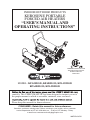
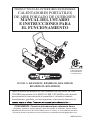
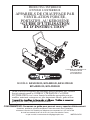
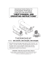
INDOOR/OUTDOOR PRODUCTS
KEROSENE PORTABLE
FORCED AIR HEATERS
“USER’S MANUAL AND
OPERATING INSTRUCTIONS”
MODEL: KFA50DGD, KFA80DGD, KFA135DGD
KFA180DGD, KFA220DGD
carefully. This USER’S MANUAL has been designed to instruct you as to
the proper manner in which to assemble, maintain, store, and most
Please keep this manual for future reference.
COMPLIES WITH UL733 AND
ANSI A10.10-1998 CAN/CSA/
B140.0-03 AND CSA
B140.8-1967
CONSUMER : Retain this manual for future reference.
Questions, problems, missing parts? Before returning to your retailer, call our customer
service department at 877-447-4768 8:30 a.m. - 4:30 pm CST, Monday - Friday.
or email us at [email protected]

1
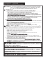
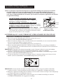
DANGER: IMPROPER USE OF THIS HEATER CAN RESULT IN SERIOUS INJURY OR DEATH
FROM BURNS, FIRE, EXPLOSION, ELECTRICAL SHOCK AND/OR CARBON
MONOXIDE POISONING.
WARNINGS:
1. RISK OF INDOOR AIR POLLUTION!
• Use this heater only in well ventilated areas. Provide at least a three-square foot (2,800 sq. cm.)
opening of fresh outside air for each 100,000 BTU/hr. of heater rating.
• People with breathing problems should consult a physician before using the heater.
• Carbon monoxide poisoning:
headaches, dizziness
and/or nausea. If you have these signs, the heater may not be working properly.
Get fresh air at once! Have the heater serviced. Some people are more affected by carbon monoxide than others.
These include pregnant women, persons with heart or lung diseas
those at high altitudes.
• Never use this heater in living or sleeping areas.
2. RISK OF BURNS / FIRE / EXPLOSION!
• NEVER use any fuel other than 1-K kerosene, #1/#2 disel/fuel oil, JET A or JP-8 fuels in this heater.
• NEVER use use fuel such as gasoline, benzene, paint thinners or other oil compounds in this heater.
(RISK OF FIRE OR EXPLOSION)
• NEVER
• NEVER ill hot.
CAUTION:
Hot while in operation. Do not touch. Keep children,
clothing and combustibles away from heater.
Minimum Clearances: Outlet: 8 feet (250cm) / Sides, top and rear: 4 feet (125cm)
• NEVER block air inlet (rear) or air outlet (front) of heater.
• NEVER use duct work in front or behind of heater.
• NEVER move or handle heater while it is hot, operating, or plugged in.
• NEVER transport heater with fuel in it’s tank.
• When used with an optional thermostat or if equipped with a thermostat, heater may start at any time.
• A
LWAYS locate heater on a stable and level surface.
• ALWAYS keep children and animals away from heater.
• Bulk fuel storage should be a minimum of 25 ft. from heaters, torches, portable generators or other sources of ignition.
All fuel storage should be in accordance with federal, state or local authorities having jurisdiction.
3. RISK OF ELECTRIC SHOCK!
•
on the model plate of the heater.
• Use only a three-prong, grounded outlet and extension cord.
• ALWAYS install the heater so that it is not directly exposed to water spray, rain, dripping water or wind.
• ALWAYS unplug the heater when not in use.
MASSACHUSETTS RESIDENTS: Massachusetts state law prohibits the use of this heater in any
building which is used in whole or in part for human habitation. Use of this heating device in
CANADIAN RESIDENTS: Use of this heater shall be in accordance with authorities having
jurisdiction and CSA Standard B139.
NEW YORK CITY RESIDENTS: For use only at construction sites in accordance with applicable NYC
NEVER LEAVE THE HEATER
UNATTENDED WHILE BURNING!
WARNING: This product and the fuel used to operate this product (kerosene or other
approved fuels), and the products of combustion of such fuel, can expose you to chemicals including
benzene, which is known to the State of California to cause cancer and reproductive harm.
For more information go to www.p65Warnings.ca.gov

2
ITEM PAGE #
PRECAUTIONS - SAFETY GUIDE ......................................................... 1
1. INTRODUCTION ............................................................................... 2
2. FEATURES .......................................................................................... 2
3. UNPACKING AND ASSEMBLY ....................................................... 4
4. FUEL SELECTION
............................................................................ 6
5. OVERVIEW OF HEATER DESIGN ................................................... 7
6. FUELING YOUR HEATER ................................................................ 8
7. OPERATION ....................................................................................... 8
8. LONG TERM STORAGE OF YOUR HEATER ................................ 9
9. MAINTENANCE ................................................................................ 10
10. REPLACING FUSE ............................................................................ 14
11. TROUBLESHOOTING GUIDE ......................................................... 15
12. WIRING DIAGRAM ........................................................................... 16
13. SPECIFICATIONS .............................................................................. 17
14. EXPLODED PARTS DRAWING ........................................................ 18 & 21 & 24
15. PARTS LIST ........................................................................................ 19, 20 & 22, 23 & 25, 26
1. INTRODUCTION
Please read this USER’S MANUAL carefully. It will show you how to assemble, maintain, and operate the
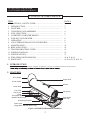
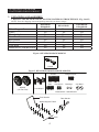
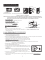
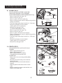
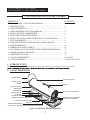
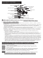
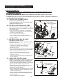
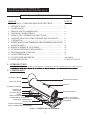
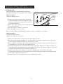
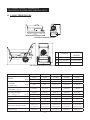
2. FEATURES
Figure 1. KFA50DGD/KFA80DGD MODELS
CONTENTS OF USER’S MANUAL
Front Guard
Hot Air Outlet
Lower Shell
Fuel Tank
Side Cover
Lamp
Thermostat Knob
(80DGD Model Only)
Power/Reset Switch
Upper Shell
Handle
Fan Guard
Fuel Gauge
Fuel Cap
Power Cord
(Piggy Back, 80DGD Model Only)
NEVER LEAVE THE HEATER
UNATTENDED WHILE BURNING!

3
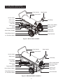
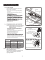
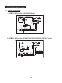
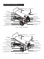
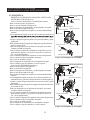
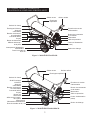
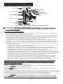
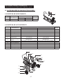
Figure 2. KFA135DGD MODEL
Figure 3. KFA180/220DGD MODELS
Hot Air Outlet
Hot Air Outlet
Front Handle
Front Handle
Cord Wrap
Cord Wrap
Pressure Gauge
Pressure Gauge
Fan Guard
Fan Guard
Fuel Drain Bolt
Fuel Drain Bolt
Power Cord
(Piggy Back)
Power Cord
(Piggy Back)
BTU Control Switch
BTU Control Switch
Rear Handle
Rear Handle
Upper Shell
Upper Shell
Shell Lower
Shell Lower
Fuel Cap
Fuel Cap
Side Cover
Side Cover
Lamp
Lamp
Fuel Gauge
Fuel Gauge
Thermostat Knob
Thermostat Knob
Power/Reset Switch
Power/Reset Switch
10” Flat Free Wheel
10” Flat Free Wheel
Room Temp. Display
Room Temp. Display
NEVER LEAVE THE HEATER
UNATTENDED WHILE BURNING!

4
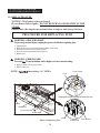
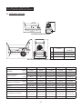
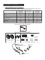
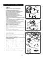
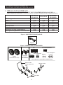
Figure 4. KFA50DGD/80DGD MODELS
Figure 5. KFA135DGD/180DGD/220DGD MODELS
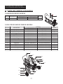
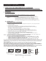
3. UNPACKING AND ASSEMBLY
1. REMOVE THE HEATER AND ALL PACKING MATERIALS FROM THE BOX. (Fig. 4 and 5)
NOTE : Save the shipping carton and packing materials for future storage.
KFA50DGD
KFA80DGD
KFA135DGD
KFA180DGD
KFA220DGD
Wheel Support Frame No Yes Yes
Wheel No Yes Yes
Threaded Axle No Yes Yes
Front Handle No Yes Yes
Rear Handle No Yes Yes
Handle Yes No No
Cord Wrap No Yes Yes
Hardware kit : HW-KFA1016 No Yes Yes
Handle
Wheels
(10” Flat Free)
Cord Wraps
Screws
Nuts Cap Nuts S
Hardware Kit : HW-KFA1016
Bushings Cap Nuts L
Flange Screws
Front Handle
Axle
Wheel Support Frame
Rear Handle
NEVER LEAVE THE HEATER
UNATTENDED WHILE BURNING!

5
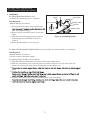
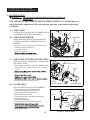
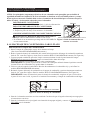
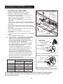
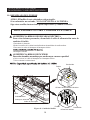
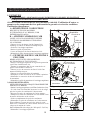
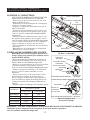
2. ASSEMBLY
For KFA50DGD/80DGD Models only
(Assembly time for this product is 3 minutes)
Tools Required
• Medium Phillips Screwdriver.
1) Lift front guard for arrow direction and make
hole on the upper housing.
2) Remove the pre-assembled screws on the shell
upper.
3) Align the holes in the upper housing with two
mounting holes on the handle as shown in
Figure 6.
4) Secure handle with the screws removed.
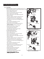
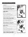
For KFA135DGD/180DGD/220DGD Models only (Assembly time for this product is 10 minutes)
Tools Required
• Medium Phillips Screwdriver.
• 3/4 inch socket or adjustable wrench
Assembling Handle & Wheel and Cord Wrap
1) Slide threaded axle through the rear section of the wheel support frame.
2) Slide one axle bushing on to each side of the axle. Slide one wheel on to each side of the axle.
Attach one cap nut on to each side of the threaded axle and tighten well.
3)
frame.
4)
5) Align the hole on the handles with the mounting hole on the Cord Wrap.
6)
Figure 6. Assembling Handle
NEVER LEAVE THE HEATER
UNATTENDED WHILE BURNING!
Handle
Screw
Front Guard
Wedged Portion
Slit Hole
Shell Upper
Remove Screws

6
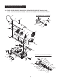
Figure 7. Assembling Handle, Wheel and Cord wrap
Cap Nut L
Wheel
Wheel Bushing
Threaded Axle
Rear Handle
Air Inlet
Cord Wrap
Cap Nut S
Nut
Hot Air Outlet
Screw
Flange Screw
Front Handle
Wheel Support Frame
Flange
Fuel Tank
NEVER LEAVE THE HEATER
UNATTENDED WHILE BURNING!
CAUTION: DO NOT OPERATE heater without support frame assembled to tank.
NOTE:
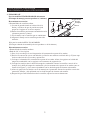
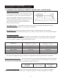
4. FUEL SELECTION
1. All models can use 7 different fuels: K1 Kerosene, #1 Fuel Oil, #1, Diesel, #2 Fuel Oil, #2 Diesel, Jet A, JP-8
2. K1 Kerosene is recommended for optimal combustion and performance, and for less maintenance. K1 is also
the optimal fuel choice in extremely low temperatures of 15°F or less, as its pour-point/"gel-point" varies
3. Jet A and JP-8 are also excellent choices for clean combustion, reduced maintenance, and temperatures below
15°F, but they are rarely found outside of the aviation industry or the military.
4. #1 Fuel Oil, #1 Diesel, #2 Fuel Oil, #2 Diesel are often selected, as they are readily available. However, the
following:
a. #1 Diesel and #1 Fuel Oil will have some degree of increased smoke/soot during ignition, increased smell,
and increased regular cleaning/maintenance.
, burn dirtier than #1 fuels. The
use of #2 fuels will result in a little more smoke/soot during ignition, a greater increase in smell, and will
require more regular cleaning/maintenance than #1 fuels.
c. At temperatures lower than 15°F, most diesel/fuel oil blends will become more viscous (start to gel) as
the diesel falls below its pour point (starts to "gel"), and may pose a challenge igniting the heater and with
continuous operation of the heater. There are troubleshooting steps for this situation, but selecting K1 (or
JP-8/Jet A) is recommended when operating below 15°F. The colder the temperatures the more likely you
could problems you will experience diesel gelling.
temperature drops. At 32°F, the wax in liquid form will crystallize and leave the fuel clouded; this can start
correct which can cause white smoke and performance problems.
NEVER store kerosene in the living space. Kerosene should be stored in a well ventilated place outside the
living area.
NEVER use any fuel other than 1-K kerosene (#1/#2 diesel/fuel oil, JET A or JP-8 fuels are acceptable substitutes)
NEVER use fuel such as gasoline, benzene, alcohol, white gas, camp stove fuel, paint thinners, or other oil
compounds in this heater. These are volatile fuels that can cause an explosion or uncontrolled
NEVER store kerosene in direct sunlight or near a source of heat.
NEVER use kerosene that has been stored from one season to the next. Kerosene deteriorates over time.
KEROSENE SHOULD ONLY BE STORED IN A BLUE CONTAINER THAT IS CLEARLY
MARKED “KEROSENE”. NEVER STORE KEROSENE IN A RED CONTAINER.
Red containers are associated with gasoline.
“OLD KEROSENE” WILL NOT BURN PROPERLY IN THIS HEATER.

7
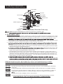
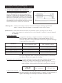
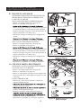
5. OVERVIEW OF HEATER’S DESIGN
Fuel System: This heater is equipped with an electric
air pump that forces air through the air
line connected to the fuel intake and then
through a nozzle in the burner head.
When the air passes in front of the fuel
intake it causes fuel to rise from the tank
and into the burner nozzle. This fuel and
air mixture is then sprayed into the
combustion chamber in a ne mist.
“Sure Fire Ignition” : The electronic ignitor sends voltage to a specially designed spark plug.
The spark plug ignites the fuel and air mixture described above.
The Air System : The heavy duty motor turns a fan that forces air into and around the combustion chamber.
Here the air is heated and then forced out the front of the heater.
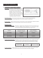
The Safety System :
A. Temperature Limit Control : This heater is equipped with a Temperature Limit Control designed to turn
off the heater should the internal temperature rise to an unsafe level. If this
device activates and turns your heater off it may require service.
B. Electrical System Protection : This heater’s electrical system is protected by a fuse mounted to the PCB
assembly that protects it and other electrical components from damage.
If your heater fails to operate check this fuse rst and replace as needed.
C. Flame-Out Sensor : Utilizes a photocell to monitor the ame in burn chamber during normal operation.
It will cause the heater to shut-off should the burner ame extinguish.
MODELS
Internal Shut-Off Temp.
Plus/Minus 10 Degrees
Reset Temperature
Plus/Minus 10 Degrees
KFA50DGD 176˚F/80˚C 122˚F/50˚C
KFA80DGD 158˚F/70˚C 104˚F/40˚C
KFA135DGD 158˚F/70˚C 104˚F/40˚C
KFA180DGD 230˚F/110˚C 194˚F/90˚C
KFA220DGD 194˚F/90˚C 140˚F/60˚C
FUSE TYPE:
All Models
125 volt / 8 amps
NEVER LEAVE THE HEATER
UNATTENDED WHILE BURNING!

8
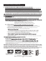
6. FUELING YOUR HEATER
NEVER FILL THE HEATER FUEL TANK IN THE LIVING SPACE : FILL THE TANK OUTDOORS.
DO NOT OVERFILL YOUR HEATER AND BE SURE HEATER IS LEVELED.
IMPORTANT NOTICE REGARDING FIRST IGNITION OF HEATER :
manufacturing the heater to burn off outside.
B.) OPERATION
TO START HEATER
2. Attach fuel cap.
3. Plug power cord of heater into three-prong, grounded extension cord. Extension cord must be at
least six feet long.
Extension Cord Wire Size Requirements
• 6 to 100 feet (1.8 to 30.5 meters) long, use 16 AWG conductor.
• 101 to 200 feet (30.8 to 61 meters) long, use 14 AWG conductor.
4. Turn “THERMOSTAT CONTROL knob” to desired setting (setting range : 40˚F ~ 110˚F)
(KFA80/135/180/220DGD Models Only)
5. Push “BTU control Switch” to desired level “High or LOW” (See Figure 8.)
(KFA135/180/220DGD Models Only)
6. Push Power Switch to “ON” position, Power lndicator Lamp will light and heater will start.
7. After startup, push “BTU control switch” to desired level “High or Low”
NOTE: Room Temperature display explanations are as follows: (KFA135/180/220DGD Models only)
• When the room temperature is less 0℉, the LED display will show “Lo”
• When room temp is between 0℉ and 99℉, the number shown on the display is the current
room temperature.
• When room temperature is greater than 99℉, the LED display will show “Hi”
If heater does not start, the thermostat setting may be too low, turn “thermostat Control Knob” to
higher position to start heater. If heater still does not start, turn power switch to “OFF” and then to
“ON” position. If heater still does not start, see Troubleshootiong Guide on page15.
NOTE : User can select to operate the heater on two different BTU levels(High or Low).
To stabilize heater and prevent ignition delay, select BTU level after turning the heater on, or
while it is in operation by pushing the BTU control switch. If the heater started at low BTU level
in cold weather or low fuel tank, i
gnition failure can occur.
NOTE : In cold weather, ignition may be improved by holding a over the end of the relief valve or
block fanguard in half with newspaper etc. until the heater ignites.
7. OPERATION
A.) VENTILATION
RISK OF INDOOR AIR POLLUTION/USE HEATER ONLY IN WELL VENTILATED AREAS.
Provide a fresh air opening of at least three square feet (2,800 sq. cm) for each 100,000 BTU/Hr.
rating. Provide extra fresh air if more heaters are being used.
Example : A KFA220DGD heater requires one of the following:
• a two-car garage door raised six inches (15.24 cm)
• a single-car garage door raised nine inches (22.86 cm)
WARNING!! : NEVER REFILL HEATER FUEL TANK WHEN HEATER IS OPERATING OR STILL HOT.
NEVER LEAVE THE HEATER
UNATTENDED WHILE BURNING!
1. Fill fuel tank with fuel.
NOTE : Kerosene is recommended when the temperature drops below 0℉(-18℃) to prevent
ignition delay or failure.

9
NEVER LEAVE THE HEATER
UNATTENDED WHILE BURNING!
NOTICE : The major electrical components of this heater are protected by a safety fuse mounted to the PCB board.
If your heater fails to start, check this fuse first and replace as necessary. You should also check your
power source to insure that proper voltage and frequency are being supplied to the heater.
TO STOP HEATER
1. Turn switch to “OFF” and unplug power cord.
TO RESTART HEATER
1.Wait 10 seconds after stopping heater.
2. Repeat steps under to start heater.
PIGGYBACK POWER CORD
WARNING : SHOCK HAZARD!
8. LONG TERM STORAGE OF YOUR HEATER
FUEL TANK DRAIN
1. Drain fuel tank through fuel cap opening.
(For KFA50DGD/80DGD Models Only)
2. Remove fuel drain bolt from rear bottom side of fuel tank using 3/4” socket or adjustable wrench and drain.
(For KFA135DGD/180DGD/220DGD Models Only. See Figure 10)
3. Using a small amount of kerosene, swirl and rinse the inside of the tank.
NEVER mix water with the kerosene as it will cause rust inside the tank.
Pour the kerosene out making sure that you remove it all.
IMPORTANT : Do not store kerosene over summer months for use during next heating season.
Using old fuel could damage heater.
4. Reinstall fuel cap. Properly dispose of old and dirty fuel.
(For KFA50DGD/80DGD Models Only)
5. Reinstall fuel drain bolt to Fuel tank and tighten firmly using 3/4” socket
or adjustable wrench.
(For KFA135DGD/180DGD/220DGD Models Only.
See Figure 10)
IMPORTANT : Before reinstalling the fuel drain bolt, make sure the
seal is on the bolt. If the seal is not used the bolt cannot
be installed correctly and the fuel tank will leak.
6. Store heater in dry well ventilated area. Make sure storage place is free
of dust and corrosive fumes.
7. Store the heater in the original box with the original packing material and keep the USER’S MANUAL
with the heater.
• Always cover electric outlet when not in use.
• Don’t plug and use an appliance more than 120V/60Hz 5A
current in this outlet.
Figure 10. Fuel Drain Bolt
Fuel Drain Bolt
Seal
revoC
KFA80DGD/135DGD/180DGD/220DGD Models only
Figure 9. Piggy Back Power Cord
Outlet
Figure 8. Controls for All Models
Power/Reset
Switch
KFA50DGD/80DGD Models KFA135DGD/180DGD/220DGD Models
Room Temp. Display
Power/Reset
Switch
Thermostat
Control Knob
(KFA80DGD MODEL ONLY)
Thermostat
Control Knob
Lamp
Lamp
Fan Guard
Btu Control Switch
Btu Control Switch
Push to"HIGH"
Push to"LOW"
Relief Valve

10
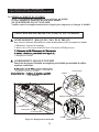
9. MAINTENANCE
WARNING!! : NEVER SERVICE HEATER WHILE IT IS PLUGGED IN OR
WHILE HOT!
USE ORIGINAL EQUIPMENT REPLACEMENT PARTS. Use of third party or
other alternate components will void warranty and may cause unsafe operating
conditions.
A.) FUEL TANK
FLUSH EVERY 200 HOURS OF OPERATION OR
AS NEEDED (SEE STORAGE, PAGE 9)
B.) AIR INTAKE FILTER
WASH AND DRY WITH SOAP AND WATER
EVERY 500 HOURS OF OPERATION OR AS
NEEDED.
- Remove screws along each side of heater using
medium phillips screwdriver.
- Lift upper shell off.
- Remove fan guard.
-
- Reinstall fan guard and upper shell.
C.) AIR OUTPUT FILTER, LINT FILTER
REPLACE EVERY 500 HOURS OF OPERATION
OR ONCE A YEAR.
- Remove upper shell and fan guard (See Air Intake Filter).
- Turn Air pressure gauge counter-clock wise and
remove.
-
phillips screwdriver.
-
-
-
- Reinstall fan guard and upper shell.
D.) FAN BLADES
CLEAN EVERY SEASON OR AS NEEDED.
- Remove upper shell (See Air Intake Filter).
- Use M6 allen wrench to loosen set screw
which holds fan blade to motor shaft.
- Slip fan blade off motor shaft.
- Clean fan blade using a soft cloth moistened with
kerosene or solvent.
- Dry fan blade thoroughly.
- Reinstall fan blade on motor shaft. Place fan
-
- Reinstall upper shell.
NEVER LEAVE THE HEATER
UNATTENDED WHILE BURNING!
Figure 11. Air Intake Filter Access
Figure 12. Air Output Filter Access
Figure 13. Fan Assembly
Screw
Upper Shell
Air Intake Filter
Air Intake Filter
Set Screw
Motor Shaft
Motor
Fan Blade
Pressure Gauge
Flush
Lint Filter
Air Output Filter
End Filter Cover
Screw
Fan Guard

11
E.) NOZZLE
REMOVE DIRT IN NOZZLE AS NEEDED (SEE PAGE 16).
(For KFA50DGD/80DGD/135DGD/180DGD Models Only)
- Remove upper shell (See page 10).
- Remove fan blade (See page 10).
- Remove fuel and air line hoses from nozzle adaptor.
- Remove ignitor wire from spark plug.
- Remove spark plug from nozzle adaptor using medium
phillips screwdriver.
- Turn nozzle adaptor 1/9 turn(40°) to counter clock wise
and pull toward motor to remove. (See Figure 14)
- Place plastic hex-body into vise and lightly tighten.
- Carefully remove nozzle from nozzle adaptor using 5/8”
socket wrench.
- Blow compressed air through face of nozzle.
(this will remove any dirt in nozzle)
- Reinstall nozzle into nozzle adaptor until nozzle seats.
Tighten 1/3 turn more using 5/8” socket wrench.
(40~45 inch-pounds)
- Reinstall nozzle adaptor to Burner Head.
- Reinstall spark plug to nozzle adaptor.
- Attach ignitor wire to spark plug.
- Attach fuel and air line hoses to nozzle adaptor.
- Reinstall fan blade and upper shell.
(For KFA220DGD Model Only)
- Remove upper shell (See page 10).
- Remove fan (See page 10).
- Remove fuel and air line hoses from nozzle adaptor.
- Remove ignitor wire from spark plug.
- Remove spark plug from nozzle adaptor using medium
phillips screwdriver.
- Turn nozzle adaptor 1/8 turn (45°) to counter clock wise
and pull toward motor to remove. (See Figure 15)
- Place plastic hex-body into vise and lightly tighten.
- Carefully remove nozzle from nozzle adaptor using 5/8”
socket wrench.
- Blow compressed air through face of nozzle.
(this will remove any dirt in nozzle)
- Reinstall nozzle into nozzle adaptor until nozzle seats
Tighten 1/3 turn more using 5/8” socket wrench
(40~45 inch-pounds)
- Reinstall nozzle adaptor to burner bracket
- Reinstall spark plug to nozzle adaptor.
- Attach ignitor wire to spark plug.
- Attach fuel and air line hoses to nozzle adaptor.
- Reinstall fan blade and upper shell.
- Reinstall upper shell.
NEVER LEAVE THE HEATER
UNATTENDED WHILE BURNING!
Figure 15. Nozzle Replacement
Figure 14. Nozzle Replacement
Fuel Line
Air Line
Nozzle Adaptor
Combustion Chamber
Screw
Ignitor Wire
Spark Plug
Bracket-Burner
Nozzle Adaptor
Nozzle Face
Nozzle
Nozzle Adaptor
Screw
Combustion Chamber
Ignitor Wire
Spark Plug
Nozzle Adaptor
Air Line
Fuel Line
Burner Head
Nozzle Adaptor
Nozzle Face
Nozzle
Nozzle Adaptor

12
F.) SPARK PLUG
CLEAN AND REGAP EVERY 600 HOURS
OPERATION OR REPLACE AS NEEDED.
(For KFA50DGD/80DGD/135DGD/180DGD Models Only)
- Remove upper shell (See page 10).
- Remove fan (See page 10).
- Remove ignitor wire from spark plug.
- Remove spark plug from nozzle adaptor using medium
phillips screwdriver.
- Clean and regap spark plug electrodes to 3.5mm gap.
- Reinstall spark plug to nozzle adaptor.
- Attach ignitor wire to spark plug.
- Reinstall fan and upper shell.
(For KFA220DGD Model Only)
- Remove upper shell (See page 10).
- Remove fan (See page 10).
- Remove ignitor wire from nozzle adaptor.
- Remove spark plug from nozzle adaptor using medium
phillips screwdriver.
- Clean and regap spark plug electrodes to 3.5mm gap.
(0.138”)
- Reinstall spark plug to nozzle adaptor.
- Attach ignitor wire to spark plug.
- Reinstall fan and upper shell.
G.) PHOTOCELL
CLEAN PHOTOCELL ANNUALLY OR AS
NEEDED.
- Remove upper shell (See page 10).
- Remove fan (See page 10).
- Remove photocell from it’s mounting.
Clean photocell lens with cotton swab.
TO REPLACE:
- Remove side cover screws using medium phillips
screwdriver.
- Disconnect switch wires from power switch and
remove side cover.
- Disconnect wires from circuit board and remove
photocell.
- Install new photocell and connect wires to circuit
board.
- Replace switch wires to power switch and side cover.
- Replace fan and upper shell.
NEVER LEAVE THE HEATER
UNATTENDED WHILE BURNING!
Screw
Spark Plug
Ignitor Wire
Side Cover
Power
Switch
Screw
Switch
Wires
Photocell
Lens
Bracket
Install Photocell
• Incorrect • Correct
Spark Plug
GAP
Nozzle Adaptor
Figure 16. Spark Plug Regap
Figure 17. Spark Plug Regap
Figure 18. Photocell Replacement
GAP
3.5mm / 0.138”
Ignitor Wire
Screw
Spark Plug
Nozzle Adaptor
Spark Plug
GAP

13
H.) FUEL FILTER
CLEAN OR REPLACE TWICE A HEATING
SEASON OR AS NEEDED.
- Remove side cover screws using medium phillips
screwdriver.
- Disconnect switch wires from power switch and
remove side cover.
-
-
remove (KFA50DGD/80DGD Models only).
-
(KFA135DGD/180DGD/220DGD Models only).
-
-
- Replace switch wires to power switch.
- Reinstall side cover.
I.) PUMP PRESSURE ADJUSTMENT
NOTE: If the pump pressure needs to be adjusted,
make sure the heater is running on the
HIGH BTU setting.
- Push the BTU CONTROL Switch to HIGH.
(See Operation, page 8, KFA135DGD/180DGD/
220DGD Models only)
- Remove Pressure Gauge Plug from End Filter Cover.
(KFA50DGD/80DGD Models only)
- Start heater (See Operation, page 8)
Allow motor to reach full speed
-
relief valve to clockwise to increase pressure. Turn
relief valve to counter clockwise to decrease pressure.
- Stop heater (See Operation, page 8)
NOTE: USE ONLY ORIGINAL EQUIPMENT
REPLACEMENT PARTS.
Use of alternate or third party components will
void any warranty and may cause unsafe
operating condition.
MODEL
Pump Pressure
High BTU level Low BTU level
KFA50DGD 3.8 psi N/A
KFA80DGD 3.8 psi N/A
KFA135DGD 5.5 psi 3.5 psi
KFA180DGD 6.5 psi 4.5 psi
KFA220DGD 8.5 psi 6.5 psi
Figure 19. Fuel Filter Replacement
Figure 20. Adjusting Pump Pressure
NEVER LEAVE THE HEATER
UNATTENDED WHILE BURNING!
Fuel Filter
Fuel line
Switch Wires
Screw
Side Cover
Power Switch
Flat blade
Screw driver
KFA50DGD/80DGD Models Only
KFA135/180/220DGD Models only
Relief Valve
Relief Valve
Pressure Gauge
Pressure Gauge
Pressure Gauge Plug
End Filter Cover.
BTU Control Switch

14
Figure 21. Replacing Fuse
10. REPLACING FUSE
NOTICE : This heater is fuse protected.
If your heater fails to ignite, DO NOT RETURN YOUR HEATER TO THE
STORE.
Please follow the simple instructions below to inspect and change the fuse.
WARNING : SHOCK HAZARD
To prevent personal injury, unplug the power cord before replacing fuse.
1. Unplug heater.
2. Remove side cover screws using medium phillips screw driver.
3. Disconnect switch wires from power switch.
4. Remove fuse from fuse holder.(See Figure 21.)
5. Replace fuse.
WARNING : FIRE HAZARD
To avoid
Do not substitute with a higher or lower current rating.
6. Replace switch wires to power switch.
7. Replace side cover.
NOTE : fuse rating : AC 125/8A
PROCEDURE FOR REPLACING FUSE
Fuse Holder
Fuse Holder
KFA80DGD/135DGD/180DGD/220DGD Models
KFA50DGD
Fuse
Fuse
Switch Wire
Power Switch
Side Cover
Screw
NEVER LEAVE THE HEATER
UNATTENDED WHILE BURNING!

15
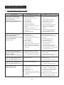
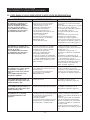
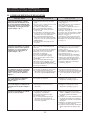
11. TROUBLESHOOTING GUIDE
TROUBLE POSSIBLE CAUSE CORRECTIVE ACTION
Heater ignites but MAIN PCB
assembly shuts heater off after a
short period of time.
(IndicatorLampisickeringand
room temp. display indicates “ E1 “)
1. Wrong pump pressure.
2. Dirty Air Output,Air Intake
or Lint Filter.
3. Dirty Fuel Filter.
4. Dirt in Nozzle.
5. Dirty Photocell Lens.
6. Photocell Assembly not
Properly installed.(Not seeing the
ame)
7. Bad electrical connection
between photocell and MAIN PCB
assembly.
8. Defective Photocell.
1. See Pump Pressure Adjustment,
Page 13.
2. See Air Output, Air intake
and Lint Filters, page 10.
3. See Fuel Filter, Page 13.
4. See Nozzle, Page 11.
5. Clean Photocell Lens, Page 12.
6. Make sure photocell boot is
properly seated in bracket,
Page 12.
7. Check electrical components
See wiring diagram, Page 16.
8. Replace Photocell, Page 12.
Heater will not ignite but motor
runs for a short period
oftime.(IndicatorLampisickering
and room temp.display
indicates “ E1 “)
1. No fuel in tank.
2. Wrong pump pressure.
3. Carbon deposits on spark plug and/
or improper gap.
4. Dirty fuel lter.
5. Dirt in Nozzle.
6. Water in fuel tank.
7. Bad electrical connection between
ignitor and MAIN PCB assembly.
8. Ignition wire is not attached to
spark plug.
1. Fill tank with kerosene.
2. See Pump Pressure Adjustment,
Page 13.
3. See Spark Plug, Page 12.
4. See Fuel Filter, Page 13.
5. See Nozzle, Page 11.
6. Flush fuel tank with clean
kerosene, Page 9.
7. Check electrical components
See wiring diagram, Page 16.
8. Attach ignition wire to spark plug.
See Spark Plug, Page 12.
Fan does not turn when heater is
plugged in and power switch was in
the “ ON “ Position.
(IndicatorLampisonorickering)
1. Thermostat setting is too low.
2. Bad electrical connection between
motor and MAIN PCB assembly.
1. Turn thermostat control knob to a
higher setting.
2. Check electrical connections, See
Wiring Diagram, Page 16.
(IndicatorLampisickeringand
room temp. display indicates “E2”)
1. Sensor Failure. 1. Replace sensor.
See Wiring diagram, Page 16.
(IndicatorLampisickeringand
room temp. display indicates “E3”)
1. Thermostat switch failure. 1. Replace switch.
See Wiring diagram, Page 16.
Heater will not turn-on
(Indicator Lamp is off)
1. Temperature limit safety device is
overheated.
2. No electrical power
3. Blown fuse.
4. Bad electrical connection between
temperature limit safety device and
PCB board.
1. Turn power switch to “OFF”
and allow to cool (about 10 min.)
2. Check to insure heater cord and
extension cord are plugged in.
Check power supply.
3. Replace safety fuse in PCB board.
4. Check electrical connections
See Wiring Diagram, Page 16.
NEVER LEAVE THE HEATER
UNATTENDED WHILE BURNING!

16
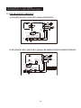
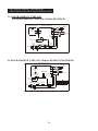
12. WIRING DIAGRAM
A) WIRING DIAGRAM (KFA50DGD Model)
B) WIRING DIAGRAM (KFA80DGD/135DGD/180DGD/220DGD Models)
NEVER LEAVE THE HEATER
UNATTENDED WHILE BURNING!
SPARK PLUG
PUMP
BLACK
BLACK
BLACK
IGNITOR
CAPACITOR
WHITE
MOTOR
GREEN
EARTH
15uF/230VAC
WHITE
CONTROL PCB
DISPLAY PCB
RED
CN3
POWER LAMP
CN1CN1
(LED)
2P
CN2
RED
PW-BLK
PW-W/H
BLACK
FUSE
LIMIT
PHOTO CELL
BLACK
POWER
BLACK
POWER
ORANGE
BLACK
WHITE
8A/125VAC
AC120V
PLUG
BLACK
60Hz
GREEN
EARTH
SWITCH
CONTROL
RED
CN7
15uF/230VAC
20uF/350VAC
135/180/220DGD
80DGD
CAPACITOR
MODEL
CONTROL PCB
BLACK
PUMP
BLACK
BLACK
CN4
ORANGE
IGNITOR
(LED)
POWER LAMP
MOTOR
WHITE
RED
CAPACITOR
GREEN
EARTH
BLK
WHT
CN5
CN6
CN1(AC1)/
CN2(AC2)/
WHITE
BLACK
LIMIT
POWER
ROOM
SENSOR
FUSE
POWER
PHOTO
CELL
THERMOSTAT
BLACK
BLACK
(TEMP. CONTROL)
SPARK PLUG
WHITE
BLACK
8A/125VAC
PLUG
60Hz
AC120V
EARTH
GREEN
BLACK
CONTROL
SWITCH
RED
RED
CN3

H
WD
16.7"(424mm)
11.7"(297mm)32.0"(813mm)
17
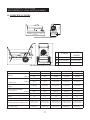
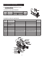
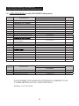
13. SPECIFICATIONS
KFA50DGD/80DGD Models
KFA135DGD/180DGD/220DGD Models
135DGD
180DGD
220DGD
D
41.9”(1,063 mm) 47.4”(1,205 mm)
W
21.5”(547 mm) 23.1”(587 mm)
H
32.4”(824 mm) 33.5”(850 mm)
MODEL KFA50DGD KFA80DGD KFA135DGD KFA180DGD KFA220DGD
BTU/Hr.
HIGH 50,000 80,000 135,000 180,000 220,000
LOW N/A N/A 95,000 140,000 180,000
Fuel Consumption
- Gal./Hr(
./Hr)
HIGH 0.38(1.44) 0.60(2.27) 1.02(3.86) 1.36(5.15) 1.66(6.28)
LOW N/A N/A 0.72(2.73) 1.06(4.01) 1.36(5.15)
Fuel Tank Capacity - Gal.(
)
5.0(18.9) 5.0(18.9) 10.0(37.9) 13.0(49.2) 13.0(49.2)
HIGH 3.8(0.27) 3.8(0.27) 5.5(0.39) 6.5(0.46) 8.5(0.60)
LOW N/A N/A 3.5(0.25) 4.5(0.32) 6.5(0.46)
Volt/Hz 120Vac/60hz 120Vac/60hz 120Vac/60hz 120Vac/60hz 120Vac/60hz
Amps. 1.6 1.6 2.5 3.2 3.7
Phase 1 1 1 1 1
Size(D×W×H), Inch(mm)
32.0×11.7×16.7
(813×297×424)
32.0×11.7×16.7
(813×297×424)
41.9×21.5×32.4
(1,063×547×824)
47.4×23.1×33.5
(1,205×587×850)
47.4×23.1×33.5
(1,205×587×850)
Weight Lbs.(kg) 26.9(12.2) 26.9(12.2) 52.2(23.7) 58.0(26.3) 60.2(27.3)
NEVER LEAVE THE HEATER
UNATTENDED WHILE BURNING!
Pump Pressure PSI(kgf/

18
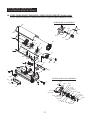
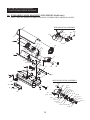
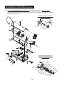
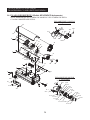
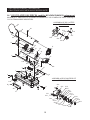
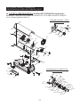
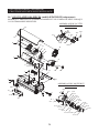
14. EXPLODED PARTS DRAWING (KFA50DGD/80DGD Models Only)
NOTE : SPECIFY MODEL NUMBER AND PART NUMBER WHEN ORDERING PARTS.
BURNER HEAD ASSEMBLY
MOTOR AND PUMP ASSEMBLY
NEVER LEAVE THE HEATER
UNATTENDED WHILE BURNING!
37
26
23
19
8
7
36
39
35
38
18
25
24
15
17
9
16
10
15
11
12
33
29
34
1
4
3
28
27
6
5
32
2
31
30
14
23-17
23-4
23-14
23-13
23-12
23-10
23-16
23-15
23-11
23-7
23-5
23-2
23-6
23-1
23-3
23-8
23-9
23-18
23-19
23-20
23-21
20-1
20-2
23-4
23-3
23-5
23-6
23-7
23-8
20
21
22
13

19
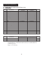
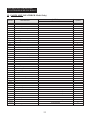
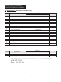
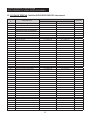
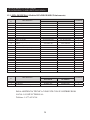
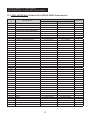
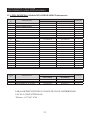
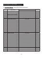
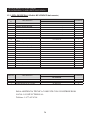
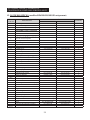
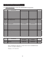
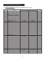
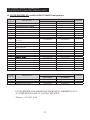
15. PARTS LIST (KFA50DGD/80DGD Models Only)
KEY NO. DESCRIPTION
PART NO.
Quantity
KFA50DGD KFA80DGD
1
2
3
4
5
6
7
8
9
10
11
12
13
14
15
16
17
18
19
20
21
22
20-1
20-2
20-3
20-4
20-5
20-6
20-7
20-8
23
23-1
23-2
23-3
23-4
23-5
23-6
23-7
23-8
23-9
23-10
23-11
23-12
Fuel Tank Assmebly
Fuel Drain-Bolt
Fuel Gauge
Fuel Filter Assmbly
Fuel Cap
Power Cord
Button Support
Display P.C.B Assembly
Shell Lower
Flange Screw
Bushing-Grommet(S)
Bushing-Grommet(L)
Air-Line
Temperature Limit Assembly
Flange-Screw
Chamber Assembly
Bracket Photocell
Screw-BH1
Photocell Assembly
Burner Head Assembly
Burner Head
Nozzle
Washer-Nozzle Seal
Spring-Nozzle Seal
O-Ring
Nozzle Adaptor
Spark Plug
Bolt-Flange
Flange Screw
Fuel Line
Motor and Pump Assembly
Motor
Capacitor
Motor Support
Nut-Hex
Holder Capacitor
Pump Body
Bolt-BH Special
Rotor
Blade
Insert
End Pump Cover
Elbow
2151-0047-01
-
2156-0049-00
2155-0005-00
2151-0041-00
3980-0275-00
-
-
3111-0501-04
4319-0015-00
3231-0120-00
3231-0121-00
3341-0035-00
2153-0013-00
4319-0015-00
2152-0293-00
3131-0159-00
4311-0068-00
*SP-KFA1007
2152-0121-00
3531-0026-00
*SP-KFA1027
4349-0016-00
3431-0010-00
3311-0002-00
3231-0178-00
*SP-KFA1008
4329-0079-00
4319-0015-00
3341-0034-00
2154-0135-00
3970-0210-00
3820-0257-00
3111-0440-00
4331-0022-00
-
3541-0022-00
4321-0198-00
See SP-KFA1000
1
See SP-KFA1000
1
See SP-KFA1000
1
3531-0027-00
3231-0181-00
1
1
1
1
1
1
2
1
1
4
1
2
1
1
1
1
1
2
1
1
1
1
2
1
1
1
1
1
3
1
1
1
1
1
2
1
1
2
1
4
1
1
1
2151-0046-01
-
2156-0047-00
2155-0005-00
2151-0041-00
3980-0274-00
3713-0048-00
215A-0013-00
3111-0501-04
4319-0015-00
3231-0120-00
3231-0121-00
3341-0035-00
2153-0022-00
4319-0015-00
2152-0292-00
3131-0159-00
4311-0068-00
*SP-KFA1007
2152-0120-00
3531-0026-00
*SP-KFA1026
4349-0016-00
3431-0010-00
3311-0002-00
3231-0178-00
*SP-KFA1008
4329-0079-00
4319-0015-00
3341-0034-00
2154-0135-00
3970-0210-00
3820-0257-00
3111-0440-00
4331-0022-00
-
3541-0022-00
4321-0198-00
See SP-KFA1000
1
See SP-KFA1000
1
See SP-KFA1000
1
3531-0027-00
3231-0181-00
NEVER LEAVE THE HEATER
UNATTENDED WHILE BURNING!
La page est en cours de chargement...
La page est en cours de chargement...
La page est en cours de chargement...
La page est en cours de chargement...
La page est en cours de chargement...
La page est en cours de chargement...
La page est en cours de chargement...
La page est en cours de chargement...
La page est en cours de chargement...
La page est en cours de chargement...
La page est en cours de chargement...
La page est en cours de chargement...
La page est en cours de chargement...
La page est en cours de chargement...
La page est en cours de chargement...
La page est en cours de chargement...
La page est en cours de chargement...
La page est en cours de chargement...
La page est en cours de chargement...
La page est en cours de chargement...
La page est en cours de chargement...
La page est en cours de chargement...
La page est en cours de chargement...
La page est en cours de chargement...
La page est en cours de chargement...
La page est en cours de chargement...
La page est en cours de chargement...
La page est en cours de chargement...
La page est en cours de chargement...
La page est en cours de chargement...
La page est en cours de chargement...
La page est en cours de chargement...
La page est en cours de chargement...
La page est en cours de chargement...
La page est en cours de chargement...
La page est en cours de chargement...
La page est en cours de chargement...
La page est en cours de chargement...
La page est en cours de chargement...
La page est en cours de chargement...
La page est en cours de chargement...
La page est en cours de chargement...
La page est en cours de chargement...
La page est en cours de chargement...
La page est en cours de chargement...
La page est en cours de chargement...
La page est en cours de chargement...
La page est en cours de chargement...
La page est en cours de chargement...
La page est en cours de chargement...
La page est en cours de chargement...
La page est en cours de chargement...
La page est en cours de chargement...
La page est en cours de chargement...
La page est en cours de chargement...
La page est en cours de chargement...
La page est en cours de chargement...
La page est en cours de chargement...
La page est en cours de chargement...
La page est en cours de chargement...
La page est en cours de chargement...
La page est en cours de chargement...
La page est en cours de chargement...
La page est en cours de chargement...
La page est en cours de chargement...
La page est en cours de chargement...
La page est en cours de chargement...
La page est en cours de chargement...
La page est en cours de chargement...
La page est en cours de chargement...
La page est en cours de chargement...
La page est en cours de chargement...
La page est en cours de chargement...
La page est en cours de chargement...
La page est en cours de chargement...
La page est en cours de chargement...
La page est en cours de chargement...
La page est en cours de chargement...
La page est en cours de chargement...
La page est en cours de chargement...
La page est en cours de chargement...
La page est en cours de chargement...
La page est en cours de chargement...
La page est en cours de chargement...
-
 1
1
-
 2
2
-
 3
3
-
 4
4
-
 5
5
-
 6
6
-
 7
7
-
 8
8
-
 9
9
-
 10
10
-
 11
11
-
 12
12
-
 13
13
-
 14
14
-
 15
15
-
 16
16
-
 17
17
-
 18
18
-
 19
19
-
 20
20
-
 21
21
-
 22
22
-
 23
23
-
 24
24
-
 25
25
-
 26
26
-
 27
27
-
 28
28
-
 29
29
-
 30
30
-
 31
31
-
 32
32
-
 33
33
-
 34
34
-
 35
35
-
 36
36
-
 37
37
-
 38
38
-
 39
39
-
 40
40
-
 41
41
-
 42
42
-
 43
43
-
 44
44
-
 45
45
-
 46
46
-
 47
47
-
 48
48
-
 49
49
-
 50
50
-
 51
51
-
 52
52
-
 53
53
-
 54
54
-
 55
55
-
 56
56
-
 57
57
-
 58
58
-
 59
59
-
 60
60
-
 61
61
-
 62
62
-
 63
63
-
 64
64
-
 65
65
-
 66
66
-
 67
67
-
 68
68
-
 69
69
-
 70
70
-
 71
71
-
 72
72
-
 73
73
-
 74
74
-
 75
75
-
 76
76
-
 77
77
-
 78
78
-
 79
79
-
 80
80
-
 81
81
-
 82
82
-
 83
83
-
 84
84
-
 85
85
-
 86
86
-
 87
87
-
 88
88
-
 89
89
-
 90
90
-
 91
91
-
 92
92
-
 93
93
-
 94
94
-
 95
95
-
 96
96
-
 97
97
-
 98
98
-
 99
99
-
 100
100
-
 101
101
-
 102
102
-
 103
103
-
 104
104


Dyna-Glo Delux Deluxe KFA180DGD Manuel utilisateur
- Taper
- Manuel utilisateur
dans d''autres langues
Documents connexes


Autres documents
-
Dyna-Glo RMC-KFA75TDGD Manuel utilisateur
-
-
Master B 35 B 70 B 100 B 150 CED Le manuel du propriétaire
-
Dura Heat DuraHeat DFA-170C Manuel utilisateur
-
Mi-T-M MH-0125-0M10 Manuel utilisateur
-
 Mi-T-M MH-0400-0M10 Manuel utilisateur
-
Homelite HHC35A Manuel utilisateur
-
 L.B. White CP170AK Owner's Manual And Instructions
-
 Prime-Line B 608 Mode d'emploi
-
 Thermoheat RMC-KFA210TL User's Manual And Operating Instructions


