Pelco ExSite Enhanced PTZ Sery Guide d'installation
- Catégorie
- Des caméras de sécurité
- Taper
- Guide d'installation

INSTALLATION
C1345M (8/19)
For EXP1230 (PTZ) Models
ExSite
®
Enhanced Series
Explosionproof Camera

C1345M (8/19)

C1345M (8/19) 1
Important Safety Instructions . . . . . . . . . . . . . . . . . . . . . . . . . . . . . . . . . . . . . . . . . . . . . . . . . . . . . . . . . . . . . . . . . . . . . . . . . . . . . . . . . . . . . . . . . . . . 3
Standards, Certificates, and Warnings . . . . . . . . . . . . . . . . . . . . . . . . . . . . . . . . . . . . . . . . . . . . . . . . . . . . . . . . . . . . . . . . . . . . . . . . . . . . . . . . . . . . . 4
Standards . . . . . . . . . . . . . . . . . . . . . . . . . . . . . . . . . . . . . . . . . . . . . . . . . . . . . . . . . . . . . . . . . . . . . . . . . . . . . . . . . . . . . . . . . . . . . . . . . . . . . . . 4
Certificates . . . . . . . . . . . . . . . . . . . . . . . . . . . . . . . . . . . . . . . . . . . . . . . . . . . . . . . . . . . . . . . . . . . . . . . . . . . . . . . . . . . . . . . . . . . . . . . . . . . . . . 4
Warnings. . . . . . . . . . . . . . . . . . . . . . . . . . . . . . . . . . . . . . . . . . . . . . . . . . . . . . . . . . . . . . . . . . . . . . . . . . . . . . . . . . . . . . . . . . . . . . . . . . . . . . . . 4
Description. . . . . . . . . . . . . . . . . . . . . . . . . . . . . . . . . . . . . . . . . . . . . . . . . . . . . . . . . . . . . . . . . . . . . . . . . . . . . . . . . . . . . . . . . . . . . . . . . . . . . . . . . . . 6
Models . . . . . . . . . . . . . . . . . . . . . . . . . . . . . . . . . . . . . . . . . . . . . . . . . . . . . . . . . . . . . . . . . . . . . . . . . . . . . . . . . . . . . . . . . . . . . . . . . . . . . . . . . 6
Parts List . . . . . . . . . . . . . . . . . . . . . . . . . . . . . . . . . . . . . . . . . . . . . . . . . . . . . . . . . . . . . . . . . . . . . . . . . . . . . . . . . . . . . . . . . . . . . . . . . . . . . . . . 6
User Supplied Parts List . . . . . . . . . . . . . . . . . . . . . . . . . . . . . . . . . . . . . . . . . . . . . . . . . . . . . . . . . . . . . . . . . . . . . . . . . . . . . . . . . . . . . . . . . . . . 6
Installation . . . . . . . . . . . . . . . . . . . . . . . . . . . . . . . . . . . . . . . . . . . . . . . . . . . . . . . . . . . . . . . . . . . . . . . . . . . . . . . . . . . . . . . . . . . . . . . . . . . . . . . . . . . 7
Wire/Cable Connections . . . . . . . . . . . . . . . . . . . . . . . . . . . . . . . . . . . . . . . . . . . . . . . . . . . . . . . . . . . . . . . . . . . . . . . . . . . . . . . . . . . . . . . . . . . . . . . 11
Connecting an FSFP Module For Integrated Transmission (Fiber, etc). . . . . . . . . . . . . . . . . . . . . . . . . . . . . . . . . . . . . . . . . . . . . . . . . . . . . . . . 14
Installing an micro SD Card . . . . . . . . . . . . . . . . . . . . . . . . . . . . . . . . . . . . . . . . . . . . . . . . . . . . . . . . . . . . . . . . . . . . . . . . . . . . . . . . . . . . . . . . 15
Accessing the Camera . . . . . . . . . . . . . . . . . . . . . . . . . . . . . . . . . . . . . . . . . . . . . . . . . . . . . . . . . . . . . . . . . . . . . . . . . . . . . . . . . . . . . . . . . . . . . . . . . 16
Mounts. . . . . . . . . . . . . . . . . . . . . . . . . . . . . . . . . . . . . . . . . . . . . . . . . . . . . . . . . . . . . . . . . . . . . . . . . . . . . . . . . . . . . . . . . . . . . . . . . . . . . . . . . . . . . 17
Installation (Mounts) . . . . . . . . . . . . . . . . . . . . . . . . . . . . . . . . . . . . . . . . . . . . . . . . . . . . . . . . . . . . . . . . . . . . . . . . . . . . . . . . . . . . . . . . . . . . . . . . . . 18
WXM200 Wall Mount . . . . . . . . . . . . . . . . . . . . . . . . . . . . . . . . . . . . . . . . . . . . . . . . . . . . . . . . . . . . . . . . . . . . . . . . . . . . . . . . . . . . . . . . . . . . 18
CMXM200 Corner Mount Adapter . . . . . . . . . . . . . . . . . . . . . . . . . . . . . . . . . . . . . . . . . . . . . . . . . . . . . . . . . . . . . . . . . . . . . . . . . . . . . . . . . . . 19
PAXM200 Pole Mount Adapter . . . . . . . . . . . . . . . . . . . . . . . . . . . . . . . . . . . . . . . . . . . . . . . . . . . . . . . . . . . . . . . . . . . . . . . . . . . . . . . . . . . . . 20
PXM200 Pedestal Mount . . . . . . . . . . . . . . . . . . . . . . . . . . . . . . . . . . . . . . . . . . . . . . . . . . . . . . . . . . . . . . . . . . . . . . . . . . . . . . . . . . . . . . . . . . 21
Dimensions . . . . . . . . . . . . . . . . . . . . . . . . . . . . . . . . . . . . . . . . . . . . . . . . . . . . . . . . . . . . . . . . . . . . . . . . . . . . . . . . . . . . . . . . . . . . . . . . . . . . . . . . . 22
Schedule Document
This document cannot be changed without prior regulatory review.

2 C1345M (8/19)

C1345M (8/19) 3
Important Safety Instructions
1. Read these instructions.
2. Keep these instructions.
3. Heed all warnings.
4. Follow all instructions.
5. To reduce the risk of ignition of hazardous atmospheres, disconnect the equipment from the supply circuit before opening. Keep assembly
tightly closed when in operation.
6. The maximum ambient temperature range is -76° to 140°F (-60° to 60°C).
7. Only use attachments/accessories specified by the manufacturer.
8. Refer all servicing to qualified service personnel. Servicing is required when the apparatus has been damaged in any way, such as power-
supply cord or plug is damaged, liquid has been spilled or objects have fallen into the apparatus, the apparatus has been exposed to rain or
moisture, does not operate normally, or has been dropped.
9. Installation should be done only by qualified personnel and conform to all local codes.
10. Use only installation methods and materials capable of supporting four times the maximum specified load.
11. Use stainless steel hardware to fasten the mount to outdoor surfaces.
12. CAUTION: Use Fasteners with yield stress greater than or equal to Class 70.
13. AN ALL-POLE MAINS SWITCH with a contact separation of at least 3 mm in each pole shall be incorporated in the electrical installation of
the building.
14. A readily accessible disconnect device shall be incorporated in the building installation wiring.
15. CAUTION: These servicing instructions are for use by qualified service personnel only. To reduce the risk of electric shock do not perform
any servicing other that contained in the operating instructions unless you are qualified to do so.
16. For Zones based installations, a certified flameproof “db,” “tb,” and IP66 sealing device, such as a stopping box with setting compound,
shall be provided either in the flameproof enclosure or immediately at the entrance thereto.
17. Use wires suitable for at least 75°C. For ambient temperatures below 14°F ( -10°C) use field wiring suitable for both minimum and
maximum ambient temperature.
18. For marine installations, ensure that the camera is installed at least 5 meters from the ship’s magnetic compass.
19. The AC Mains unit shall be connected to a circuit breaker rated maximum 15A or 20A.
20. This product requires a surge protector device (SPD) or surge arrestor as part of the installation to address transient overvoltages exceeding
Overvoltage Category II, 2500 Vpk.

4 C1345M (8/19)
Standards, Certificates, and Warnings
STANDARDS
CERTIFICATES
WARNINGS
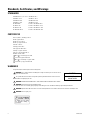
The product and/or manual may bear the following marks:
WARNING: This symbol indicates that dangerous voltage constituting a risk of electric shock
is present within this unit.
This symbol indicates that there are important operating and maintenance instructions in the
literature accompanying this unit.
WARNING: HAZARDOUS MOVING PARTS. KEEP FINGERS AND OTHER BODY PARTS AWAY.
WARNING: Potential Electrostatic Charging Hazard
Clean the enclosure surface by gently wiping it with a damp, lint-free cloth before handling or performing maintenance.
WARNING: Optical fiber cable must meet local codes and requirements for installation and connector must be secured by a latch.
WARNING: Do not repair joints.
EN 60079-0: 2012 / A11: 2013 IEC 60079-0: 2011
EN 60079-1: 2014 IEC 60079-1: 2014
EN 60079-28: 2015 IEC 60079-28: 2015
EN 60079-31: 2014 IEC 60079-31: 2013
UL 60079-0 6th CSA C22.2 No 60079.0: 2015
UL 60079-1 7th CSA C22.2 No 60079-1: 2016
UL 60079-31 2nd CSA C22.2 No 60079-31: 2015
UL 60079-28 2nd Ed CSA C22.2 No 60079-28: 2016
CLASS I, ZONE 1, AEx db op pr IIC T6
AEx tb op pr IIIC T85°C
AEx db op is op pr IIC T6
AEx tb op is op pr IIIC T85°C
IECEx UL 17.0011X
Ex db op pr IIC T6 Gb X
Ex tb op pr IIIC T85°C Db X
Ex db op is op pr IIC T6 Gb X
Ex tb op is op pr IIIC T85°C Db X
DEMKO 17 ATEX 1834X
0539 II 2 G Ex db op pr IIC T6 Gb
II 2 D ex tb op pr IIIC T85°C Db
0539 II 2 G Ex db op is op pr IIC T6 Gb
II 2 D Ex tb op is op pr IIIC T85°C Db
CAUTION:
RISK OF ELECTRIC SHOCK.
DO NOT OPEN.

C1345M (8/19) 5
WARNING: TO REDUCE THE RISK OF IGNITION OF HAZARDOUS ATMOSPHERES, DISCONNECT THE EQUIPMENT FROM THE SUPPLY CIRCUIT
BEFORE OPENING. DO NOT OPEN WHEN AN EXPLOSIVE GAS/DUST ATMOSPHERE IS PRESENT. KEEP ASSEMBLY TIGHTLY CLOSED WHEN
OPERATING. TO REDUCE THE RISK OF IGNITION OF HAZARDOUS ATMOSPHERES, ALL CONDUIT RUNSMUST HAVE A SEALING FITTING PLACED
WITHIN 2” OF THE ENCLOSURE. REFER TO MANUAL FOR INSTALLATION.
PERIGO. PARA REDUZIR O RISCO DE IGNIÇÃO EM ATMOSFERAS POTENCIALMENTE EXPLOSIVAS DESCONECTE O EQUIPAMENTO DO SISTEMA
DE ALIMENTAÇÃO ANTES DE ABRì-LO. MANTER O CONJUNTO CUIDADOSAMENTE FECHADO DURANTE A OPERAÇÃO TODOS OS CONDUITOS
DEVEN POSSUIRUNIDADE SELADORA INSTALADA ATE 5.0CM DO INVOLUCRO PARA INSTALAÇÃO REFERIR SE O MANUAL.
AVERTISSEMENT: AFIN DE RÉDUIRE LE RISQUE D'INCENDIE DANS DES ATMOSPHÈRES DANGEREUSES, DÉBRANCHEZ L'ÉQUIPEMENT DU
CIRCUIT ÉLECTRIQUE AVANT DE L'OUVRIR. NE PAS OUVRIR EN PRÉSENCE DE GAS EXPLOSIF OU DANS UNE ATMOSPHÈRE POUSSIÈREUSE.
FERMEZ BIEN L'ASSEMBLAGE AVANT TOUTE UTILISATION. AFIN DE RÉDUIRE LE RISQUE D'INCENDIE DANS DES ATMOSPHÈRES
DANGEREUSES, TOUS LES CONDUITS DOIVENT ÊTRE ÉQUIPÉS D'UN RACCORD D'ÉTANCHÉITÉ SITUÉ À 5,0 CM DU BOÎTIER. REPORTEZ-VOUS
AU MANUEL POUR OBTENIR LES INSTRUCTIONS D'INSTALLATION.

6 C1345M (8/19)
Description
ExSite
®
Enhanced Series is an explosionproof integrated positioning system with a built-in 1000Base-TX/100Base-TX network interface for live
streaming using a standard Web browser. The integrated ExSite
®
Enhanced power module supplies power in 48 VDC or 100 to 240 VAC models.
MODELS
PARTS LIST
The following parts and tools are supplied:
USER SUPPLIED PARTS LIST
You may or may not need a pipe nipple depending on the type of gland(s) you use. You will need one or two sealing glands depending on whether
you use one or both of the unit’s cable entries. If using a single cable entry, you must provide a suitably-rated stopping plug for the other entry.
Refer to the installation instructions for more information about plug selection.
For Zones based installations, the pipe nipple, stopping plug and/or conduit sealing fitting must be certified flameproof “db,” “tb,” and IP66, IP67,
and IP68.
Model Number PTZ/Fixed Camera / Lens Input Voltage Illuminator
EXP1230-4N
PTZ
1080p 30x 48 VDC None
EXP1230-7N 1080p 30x 100-240 VAC None
EXP1230-7M 1080p 30x 100-240 VAC 850 nm near-IR
Qty Description
1 ExSite Enhanced Series Explosion Proof Camera System
4 Bolts, M10 x 16 mm, stainless steel
4 Lock Washers
1 Custom Spanner Wrench
(NOTE: This tool is only used to open and close the wiring connection access door and the cap access door. The wiring connection access
door and the cap access door are the only covers that are allowed to be opened.)
1 Power Connector
1 20-Pin Alarm/Relay Connector
1 Ground Ring Terminal
1 M4 x 8 mm Pan Head Slotted Ground Screw
1 1.5mm Hex Bit, 1/4" Shank
1 Ferrite for Power Cable (Type 28A0640-0A2)
2 Ferrites for Alarms/Relays and Ethernet Cables (Type 28A2024-0A2)
2 M3 x 4mm Set Screws
1 12 - 28 AWG Splicing Connector
1-2 Pipe Nipples, 3/4-inch NPT, 1-3/8-inch L
1 Conduit Sealing Fitting, 3/4-inch NPT, F/F, Metric Adapter (if needed)
1 Conduit Fitting Sealant
1 Safety Strap or Cable
1 3/4” NPT Conduit Plug (if not using both conduit entries)

C1345M (8/19) 7
Installation
Ensure that power is off before attempting to connect and wire the camera.
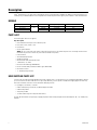
1. Attach a safety strap or cable (not supplied) in the hole shown below. Use a safety strap or cable during installation, when attaching the
camera on a mount, or in case there is ever a screw or mount failure.
Figure 1. Attach a Safety Strap or Cable in the Hole Shown Above
2. Attach the camera to the mounting surface. Use only installation methods and materials capable of supporting four times the maximum
specified load of the system.
3. Make sure the threads on the underside of the camera and the threads of the four M10 x 16 mm stainless steel bolts (supplied) are free of
dirt and debris.
4. Secure the camera to the mounting surface with the four M10 x 16 mm stainless steel bolts and lock washers (supplied).
Safety Strap
or Cable hole

8 C1345M (8/19)
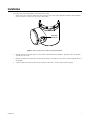
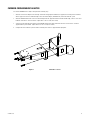
5. Using the 8 mm Allen wrench, tighten the bolts to 25 to 27 ft-lb (34 to 37 N-m).
Figure 2 shows the power module section of the camera being installed on a pedestal mount (part number PXM200, not supplied). A wall mount
is also available (part number WXM200, not supplied).
Figure 2. Attach the Camera to the Mounting Surface
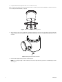
6. Attach a minimum, 4 mm^2 copper stranded wire to the bonding attachment point on the unit using a Ground Ring Terminal and M4 x 8mm
Slotted Pan Head Ground Screw (supplied). Connect the bonding attachment point on the unit to an appropriate grounding location for your
installation.
Figure 3. Bonding Attachment Point on the Unit
7. Remove the plastic plug protecting the 3/4" NPT conduit entry point.
NOTE: Do not use the plastic plugs to seal a conduit entry. If only using a single conduit entry, you must use a suitable EX plug to seal the
other entry point.

C1345M (8/19) 9
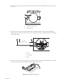
8. Remove the wiring connection access door with the Pelco-supplied spanner wrench. DO NOT REMOVE the plastic screws on the side of the
access tube.
9. Route the power, Ethernet, relays, and alarm cabling through the user-supplied cable gland and seal using the recommended gland
installation practices. There are two conduit entries; you can choose either side or run data in one and power through the other depending
on the best cable routing.
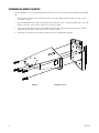
10. Clamp ferrites on each cable in use (one for Ethernet, one for alarms/relays, and one for power). Each cable should make two turns through
the ferrite, except for the AC mains power cable, which will pass through the ferrite just once..
Figure 4. Clamping Ferrites Using Two Turns
1 Wiring Connection Access Door
2 Conduit Entry Points
1 Cabling
2 Sealed Conduit
3 Nipple
u
v
CAT
6

10 C1345M (8/19)
11. Connect the wiring, refer to Wire/Cable Connections on page 11.
12. When you have connected all cabling, re-attach the wiring connection access door with the Pelco-supplied spanner wrench.
13. When the access door is completely installed, remove the plastic thread protection screws on the side of the access tube and replace them
with the supplied M3 x 4mm Set Screws. Torque the screws to 0.84 N-m using the supplied 1.5mm hex bit.
NOTE: For servicing after installation, remove the two set screws completely from the side of the access tube and then thread them back in two
full turns. Remove the Access door to access all connections. After reinstalling the access door, fully tighten the set screws to 0.84N-m.

C1345M (8/19) 11
Wire/Cable Connections
NOTES:
• Relay 2 is allocated specifically for an external washer (not supplied by Pelco).
• All relays are specified for 30 VDC, 0 to 50 mA (signal only)
• To connect the ground wire:
– Crimp a 12 AWG Ground wire to the Ground Ring Terminal (supplied). Secure the Ring Terminal to the chassis using the M4 x 8 mm
Slotted Pan Head Ground Screw (supplied).
• Two wires can be connected to the connector’s remote reset pins (See Table A) and routed to an external switch/button in a non-hazardous
location in order to remotely reset the unit.
WARNING: Be sure to seal the cable entry conduit fitting with the appropriate sealant (not supplied) during installation.
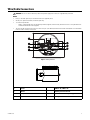
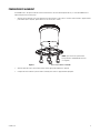
Figure 5. Wiring Interface
1 Power 5 1000Base-TX / 100Base-TX
2 Alarms 6 FSFP/Integrated Transmission
3 Relays 7 Input FSFP Transmission Speed Toggle
4 Remote Reset 8 Bonding Attachment Hole

12 C1345M (8/19)
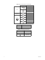
Table A. Relay and Alarm Connections (20 to 26 AWG)
Designation Function
Relays
Relay 2 N.C. (washer only)
Relay 2 COM (washer only)
Relay 2 N.O. (washer only)
Relay 1 N.C.
Relay 1 COM
Relay 1 N.O.
Remote Reset
Reset +
Reset -
Alarms
Alarm 1 +
Alarm 1 -
Alarm 2 +
Alarm 2 -
Alarm 3 +
Alarm 3 -
Alarm 4 +
Alarm 4 -
Table B. 48 VDC Wire Descriptions
Label Function
+ +48 VDC
- -48 VDC
Table C. 100 to 240 VAC Wire Descriptions
Label Function
L Live
N Neutral
Earth Ground

C1345M (8/19) 13
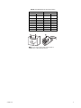
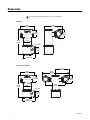
Table D. RJ-45 Network Connector Pin Descriptions
10/100BASE-TX 1000BASE-TX
Pin Function Pin Function
1TX+1BI_DA+
2 TX- 2 BI_DA-
3 RX+ 3 BI_DB+
4 Not used 4 BI_DC+
5 Not used 5 BI_DC-
6 RX- 6 BI_DB-
7 Not used 7 BI_DD+
8 Not used 8 BI_DD-
1
2
3
4
5
6
7
8
1
2
3
4
5
6
7
8
8
8
1
1
NOTE: Connect a Cat5 or higher cable (Cat5e minimum for
1000Base-TX) to a RJ-45 network connector.

14 C1345M (8/19)
CONNECTING AN FSFP MODULE FOR INTEGRATED TRANSMISSION (FIBER, ETC)
The FSFP sub-module installs in the connector cage located on the unit corresponding to the port assignment to be used. The sub-module is
keyed and can only be installed in one orientation; it uses a bale clasp to secure the FSFP sub-module in a connector cage.
To install an FSFP Module:
1. Flip the module’s bale clasp up.
2. Line the FSFP sub-module with the port, and slide it into place. The module will lock into place, indicating that it is installed properly.
3. When you are ready to attach the optical fiber cable, remove the rubber plugs from the sub module and save for future use.
4. Use the FSFP switch to set the internal transmission speed (1000 or 100 Mbps).
NOTE: If using a FSFP that is not optical fiber, you will need to Clamp 1 ferrite on the cable in use. The cable should make two turns through
the ferrite.
NOTE: Optical fiber cables shall be used provided by additional armouring, conduit, cable tray or raceway.
NOTE: Pelco FSFP modules are only compatible with LC and SC type fiber connectors.

C1345M (8/19) 15
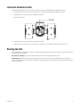
INSTALLING AN MICRO SD CARD
The unit must be powered off for you to insert an micro SD card. You should use an unformatted micro SD card for best results.
1. Remove the two set screws on both sides of the cap access door completely and then thread them back in two full turns.
2. Remove the cap access door with the Pelco-supplied spanner wrench.
3. Insert the micro SD card
4. Reattach the cap access door with the Pelco-supplied spanner wrench.
5. Tighten the set screws on both sides of the cap access door. Torque the screws to 0.84 N-m using the supplied 1.5mm hex bit.
Starting the Unit
When you apply power to the camera, the camera will self-calibrate, panning and tilting, for up to 2 minutes and 30 seconds. Visually ensure that
the camera performs this calibration.
If the calibration completes: the unit will establish a network connection and you can begin using the camera.
If calibration fails: the unit will establish a connection, but will revert to a “fixed” mode, in which you cannot pan or tilt the camera. If this
occurs, cycle power to the unit; if the camera fails to complete its self-calibration again, you should contact Pelco support and return the camera
for repair or replacement.
SD Slot

16 C1345M (8/19)
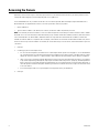
Accessing the Camera
By default, users do not have to log in to view video; anyone who accesses the camera can view live video. If you want to prevent users from
viewing video without logging in, you must change the permissions for public users.
The recommended browsers for your camera are the latest version of Internet Explorer®, Microsoft™ Edge™, Google Chrome™ browser or
Mozilla® Firefox®. For supported browser versions, refer to the Specification Sheet for your product.
1. Open a web browser.
2. Type the camera’s IP address (192.168.0.20) or host name in your browser’s address bar, and then press Enter.
NOTE: You can obtain your camera’s IP address or access the camera using the Pelco Device Utility or VxToolbox software. If DHCP is enabled
but a DHCP server is not on the network, the camera automatically assigns itself both an IPv4 link local address(169.254.x.x, where the lower two
octets are random) and a 192.168.0.20 address. Additional cameras will assign themselves different IPv4 link local addresses and the next
available 192.168.0.x IP addresses in sequential order. For example, if three cameras are connected to a network without a DHCP server, the first
camera to connect assigns itself the IP address 192.168.0.20, the second camera assigns itself 192.168.0.21, and the third camera assigns itself
192.168.0.22.
3. Click login.
4. If needed, type your user name and password.
• In its out-of-the-box configuration, the camera has no user name and password assigned. For security purposes, it is recommended that
you set an administrative user name and password after initial configuration of the camera. Creation of an administrative user name
changes the state of the camera to its “operational mode,” where credentials must be provided in order to change its configuration.
• There is no provision for recovering a forgotten administrator user name or password. The camera can be restored to its out-of-the box,
no-password configuration by powering down, depressing the reset button with an object such as a paper clip, and holding the button
down for at least five seconds while powering the camera back up. This can only be performed in a safe environment which means it
cannot be opened in a hazardous atmosphere. Alternatively, the remote reset function can be used as long as the camera was wired
for this (See Table A).
• If a user name and password exist, a Login link appears in the upper right area of your web browser.
5. Click Log In.

C1345M (8/19) 17
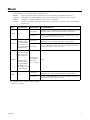
Mounts
The ExSite Enhanced Series (PTZ models) includes several mount options.
WXM200 Wall mount designed to mount the ExSite
Enhanced Series system directly to a load-bearing vertical surface.
CMXM200 Corner adapter for use with the WXM200 to mount an ExSite Enhanced Series system to the corner of a structure.
PAXM200 Pole adapter for use with the WXM200 to mount a system to a horizontal pole.
PXM200 Pedestal mount designed to mount an ExSite Enhanced Series system directly to a horizontal surface in either an upright or
inverted position.
*Recommended strength of concrete is 3,600 psi or 25 Mpa.
**Minimum of 1/8-inch wall.
Model Supplied Hardware Mounting Surface Recommended Hardware
WXM200 None
Solid Concrete*
Five 3/8-16 x 1-9/16-inch long stainless steel drop-in anchors and five 3/8-16 x 1.0-inch
thread length, stainless steel hex head bolts with stainless steel lock washers
Steel I Beam**
Five 3/8-16 x 1.0-inch thread length, stainless steel hex head bolts with stainless
steel lock washers and 3/8-16 stainless steel nuts
CMXM200
Five M10x1.5x20 mm
thread length, stainless
steel socket head bolts
with lock washers to
attach the adapter to the
WXM200 wall mount
Solid Concrete*
Six 1/2-13 x 2-inch stainless steel drop-in anchors and six 1/2-13 x 1.0-inch thread
length, stainless steel hex head bolts with stainless steel lock washers
Steel I Beam**
Six 1/2-13 x 1.0-inch thread length, stainless steel hex head bolts with stainless
steel lock washers and 1/2-13 stainless steel nuts
PAXM200
Four 5/8-inch wide x
40-inch (101.6 cm) long
stainless steel straps to
attach the adapter to a
pole
Five M10x1.5x20 mm
thread length, stainless
steel socket head bolts
with lock washers to
attach the adapter to the
WXM200 wall mount
Steel pole with a
diameter between
4 and 9 inches
(10.16 to 22.86 cm)
Supplied
PXM200 None
Solid Concrete*
Five 3/8-16 x 1-9/16-inch long stainless steel drop-in anchors and five 3/8-16 x 1.0-inch
thread length, stainless steel hex head bolts with stainless steel lock washers
Steel I Beam**
Five 3/8-16 x 1.0-inch thread length, stainless steel hex head bolts with stainless
steel lock washers and 3/8-16 stainless steel nuts

18 C1345M (8/19)
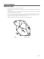
Installation (Mounts)
WXM200 WALL MOUNT
To install the WXM200 refer to Figure 6 and perform the following steps:
1. Determine the mounting location. The mounting surface should be able to support four times the combined weight of the mount and ExSite
Enhanced system.
2. Using the flanged end of the wall mount as a template, mark the five fastener hole positions onto the mounting surface. Set the WXM200
mount to the side and prepare the holes for the fasteners.
3. Position the wall mount over the mounting holes. Attach the mount to the mounting surface with the appropriate hardware (not supplied).
4. Secure the ExSite Enhanced power module to the WXM200 with the 8 mm Allen wrench and four M10 x 16 mm stainless steel bolts
supplied with the power module. Tighten the bolts to 25 to 27 ft-lb (34 to 37 Nm).
5. Complete the ExSite Enhanced system installation following the instructions supplied with the equipment.
Figure 6. WXM200 Installation
La page est en cours de chargement...
La page est en cours de chargement...
La page est en cours de chargement...
La page est en cours de chargement...
La page est en cours de chargement...
La page est en cours de chargement...
La page est en cours de chargement...
-
 1
1
-
 2
2
-
 3
3
-
 4
4
-
 5
5
-
 6
6
-
 7
7
-
 8
8
-
 9
9
-
 10
10
-
 11
11
-
 12
12
-
 13
13
-
 14
14
-
 15
15
-
 16
16
-
 17
17
-
 18
18
-
 19
19
-
 20
20
-
 21
21
-
 22
22
-
 23
23
-
 24
24
-
 25
25
-
 26
26
-
 27
27


Pelco ExSite Enhanced PTZ Sery Guide d'installation
- Catégorie
- Des caméras de sécurité
- Taper
- Guide d'installation
dans d''autres langues
Documents connexes
Autres documents
-
Videotec MAXIMUS MHX Manuel utilisateur
-
-
Bosch EXTEGRA IP 9000 FX NXF-9x30 Guide d'installation
-
Videotec MAXIMUS MPXR SERIES2 Manuel utilisateur
-
-
-
 Federal Signal G-STR Global Series Signaling Platform – Strobe Manuel utilisateur
-
MEDC DB4B UL Le manuel du propriétaire
-
MEDC DB3B Tehcnical Le manuel du propriétaire
-
ABB 266Dx Operating Instructions Manual
