Amprobe R-115S & RC-120S Manuel utilisateur
- Taper
- Manuel utilisateur


English
R-115S
RC-120S
Recom relay switch
User Manual
6/2018, 6010975 A
©2018 Amprobe
All rights reserved. Printed in China

Limited Warranty and Limitation of Liability
Your Amprobe product will be free from defects in material and
workmanship for one year from the date of purchase unless
local laws require otherwise. This warranty does not cover fuses,
disposable batteries or damage from accident, neglect, misuse,
alteration, contamination, or abnormal conditions of operation
or handling. Resellers are not authorized to extend any other
warranty on the behalf of Amprobe. To obtain service during the
warranty period, return the product with proof of purchase to an
authorized Amprobe Service Center or to an Amprobe dealer or
distributor. See Repair Section for details. THIS WARRANTY IS YOUR
ONLY REMEDY. ALL OTHER WARRANTIES - WHETHER EXPRESS,
IMPLIED OR STATUTORY - INCLUDING IMPLIED WARRANTIES OF
FITNESS FOR A PARTICULAR PURPOSE OR MERCHANTABILITY, ARE
HEREBY DISCLAIMED. MANUFACTURER SHALL NOT BE LIABLE
FOR ANY SPECIAL, INDIRECT, INCIDENTAL OR CONSEQUENTIAL
DAMAGES OR LOSSES, ARISING FROM ANY CAUSE OR THEORY.
Since some states or countries do not allow the exclusion or
limitation of an implied warranty or of incidental or consequential
damages, this limitation of liability may not apply to you.
Repair
All Amprobe returned for warranty or non-warranty repair or
for calibration should be accompanied by the following: your
name, company’s name, address, telephone number, and proof
of purchase. Additionally, please include a brief description of the
problem or the service requested and include the test leads with
the meter. Non-warranty repair or replacement charges should be
remitted in the form of a check, a money order, credit card with
expiration date, or a purchase order made payable to Amprobe.
In-warranty Repairs and Replacement – All Countries
Please read the warranty statement and check your battery
before requesting repair. During the warranty period, any
defective test tool can be returned to your Amprobe distributor
for an exchange for the same or like product. Please check
the “Where to Buy” section on amprobe.com for a list of
distributors near you. Additionally, in the United States and
Canada, in-warranty repair and replacement units can also be
sent to an Amprobe Service Center (see address below).

Non-warranty Repairs and Replacement – United States
and Canada
Non-warranty repairs in the United States and Canada should be
sent to an Amprobe Service Center. Call Amprobe or inquire at
your point of purchase for current repair and replacement rates.
USA: Canada:
Amprobe Amprobe
Everett, WA 98203 Mississauga, ON L4Z 1X9
Tel: 877-AMPROBE (267-7623) Tel: 905-890-7600
Non-warranty Repairs and Replacement – Europe
European non-warranty units can be replaced by your Beha-
Amprobe distributor for a nominal charge. Please check the
“Where to Buy” section on beha-amprobe.com for a list of
distributors near you.
Beha-Amprobe
Division and reg. trademark of Fluke Corp. (USA)
Germany* United Kingdom
In den Engematten 14 52 Hurricane Way
79286 Glottertal Norwich, Norfolk
Germany NR6 6JB United Kingdom
Phone: +49 (0) 7684 8009 - 0 Phone: +44 (0) 1603 25 6662
beha-amprobe.de beha-amprobe.com
The Netherlands - Headquarters**
Science Park Eindhoven 5110
5692 EC Son
The Netherlands
Phone: +31 (0) 40 267 51 00
beha-amprobe.com
*(Correspondence only – no repair or replacement available
from this address. European customers please contact your
distributor.)
**single contact address in EEA Fluke Europe BV


1
Recom Relay Switch
CONTENTS
INTRODUCTION ...................................................2
APPLICATIONS .....................................................2
SAFETY INFORMATION .......................................3
INSTALLATION INSTRUCTIONS ...........................4
R-115S / RC-120S INSTALLATIONS ......................8
INSTALLING IN A METAL BOX ............................. 9
R-115S HOOK-UP DIAGRAM ............................... 11
RC-120S HOOK-UP DIAGRAM ............................. 11
R-115S SPECIFICATIONS ......................................12
RC-120S SPECIFICATIONS ....................................13

2
INTRODUCTION
• Each REMCON relay, unlike any other low
voltage relay, has a built-in transformer for
unit control. Each relay in the system operates
independently and has no effect on other relays.
You can economically install as little as one relay
and operate it with as many switches desired.
• Only 6 volts on switch legs. That means no
Romex or armored cable* to pull; just light,
pliable #18 wire. *Where code permits
• Simpler wiring. No need to wire back to a
separate, low voltage transformer. You simply
connect the low-voltage wires to the terminals.
• Silent operation. Low relay noise level permits
installation of relay, right at the fixture. No
need to mount in a remote location.
• Relay cannot burn out if low voltage switch
legs are shorted.
• R-115S and RC-120S are solid state relays.
APPLICATIONS
• 3-way (or more) switching of a light
• Individual switch controls
• Converting closet lights to operate from door
jamb switches
• Outside lights with indoor switching control

3
SAFETY INFORMATION
� CAUTION
• Improper connection of power leads will result
in permanent damage to the relay. Re-check
your wiring before turning on AC power!
• To control relay, use only REMCON momentary-
contact switch or equivalent. If any old
REMCON control switches containing a light
bulb exist in the installation, the light bulb
must be removed from these switches, or
improper relay operation will result!
• The R-115S cannot be used to replace the R-4115.
• Do not exceed ratings of 6.5 AMPS AC resistive,
tungsten or ballast load, or 1/4 HP motor load.
• Do not install relay in a location where the
temperature may exceed 104 °F (40 °C).
• Incorrect hook-up can result in an electrical
hazard.
• Note: If there is more than one relay on a circuit,
the relays must all be the same type (i.e. all
R-115 or all R-115S). They cannot be intermixed
because of the difference in control currents.
• Improper connection of power leads will result
in permanent damage. Re-check your wiring
before turning on AC power to line.

4
INSTALLATION INSTRUCTIONS
REMCON Remote-Control Switching:
Connecting Relays in Circuits
When installing more than one relay, tag each
switch leg with the relay number so that circuits can
be easily identified when finish wiring is done.
Note: For generic instructions of connecting relays in
the circuits see page 6.
1. Rough in service and branch circuits. Mount boxes
at the fixture locations to be controlled. Run high-
voltage wiring to each box. Break out knockouts
to be used for relay. All uncontrolled outlets are
wired in conventional fashion. REMCON relays
should not be mounted at this stage of wiring to
avoid any possibility of damage.
2. Mount plater ring MB-1 for switch supports at all
switch locations. Each MB-1 can accommodate up
to 3 switches. Mount the MB-1 horizontally.
3. Run #18 3-conductor low-voltage thermoplastic
wire from each relay location to its switch
location. Use a staple gun and simply staple-as-
you-go. Leave a 12-inch loop on both switches
and relay ends. Wire should be installed in
workmanlike manner so that other trades will
not injure the thermoplastic covering.

5
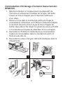
4. Match the thin, low-voltage RED, BLACK and
WHITE wires coming from the REMCON relay
cylinder to low-voltage wires in the fixture
outlet box. All wire connections must be securely
made. It Is recommended that tape be used for
connection. Where wire nuts are used, stagger
the connection. Then, slip the relay through the
proper knockout. Spring clips on sides will hold
the relay securely in place.
5. Connect the high-voltage line to relay and fixture.
6. Attach switch assembly plate to switch mounting
bracket. Pull 3 conductor #18 wire through
wall opening and connect securely to the
three terminals of the switch. Terminals are
marked RED, WHITE, and BLACK. Just match
the thin low-voltage wires to the colored switch
terminals. Then snap switches firmly into switch
assembly plate. (Plate is marked for 1, 2 or 3 gang
switches.) There is no restriction on the number of
switches that can be hooked up to the same relay.
7. Attach switch plate with screws provided,
making sure that ON is on top. When installing
the clear plastic switch plate be sure to insert
gold-tone card.

6
1
3
4 5
6 7
2
INSTALLATION
INSTRUCTIONS
Optional Accessory
Part Number: 3184256
Description: MB-1, MOUNTING BRACKET

7
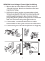
REMCON Low-Voltage Closet-Light Switching
1. Mount box at closet fixture location and run
120-volt line box. Break out knockout for later
insertion of relay.
2. Drill hole in door jamb to accommodate switch.
String 2-conductor #18 wire from door jamb and
pull through knockout in box. Connect 2 wires
projecting from cylinder of relay to the 2-conductor
#18 wire and insert relay through knockout.
3. Connect the 2-conductor #18 wire to switch.
Insert switch in door jamb and secure with screws.
4. Connect relay to 120-volt line (Shown in diagram).
1 2
3 4

8
R-115S / RC-120S INSTALLATIONS
1. Turn off AC power to circuit which you will be
wiring the R-115S or RC-120S into (using fuse or
circuit breaker).
2. Mount R-115S or RC-120S relay in a metal box
near the load to be switched as shown in section
“Installing in A Metal Box” on page 9.
3. Connect control wiring (light-guage wires) to
R-115S or RC-120S.
4. Connect AC power wiring and load wiring to
R-115S or RC-120S as shown in diagram.
�CAUTION
• Refer to the safety information on page 3
before applying AC power to the REMCON
R-115S or RC-120S circuit.
• Improper connection of power leads will
result in permanent damage. Re-check your
wiring before turning on AC power to line.
5. Restore AC power to line.
6. R-115S: When control switch momentarily
connects white control to red control wire,
power to load is turned ON. When control switch
connects white control wire to black control wire,
power to load is turned OFF. Contact state of the
R-115S is maintained even if AC power to the
relay is lost and is then restored.
RC-120S: When control switch terminals are
closed, power is ON.

9
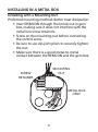
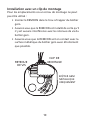
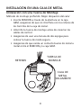
INSTALLING IN A METAL BOX
Installing with a Mounting Nut
Preferred mounting method: Better heat dissipation
• Insert REMCON through the knock-out in gem
box, making sure it does not interfere with the
metal box screw retainers.
• Screw on the mounting nut before connecting
the control wires.
• Be sure to use slip-joint pliers to securely tighten
the nut.
• Make sure there is a good metal-to-metal
contact between the REMCON and the gem box.
SCREW
RETAINER
MOUNTING
NUT
METAL BOX
ONLY

10
Installing with a Mounting Clip
For locations where a mounting nut cannot be used:
• Insert REMCON through the knock-out hole in
the gem box.
• Make sure the REMCON is installed so that there is
no interference with the gem box screw retainers.
• Make sure the REMCON contacts the metal
surface of the gem box as tightly as possible.
SCREW
RETAINER
MOUNTING
CLIP
METAL GEM
BOX ONLY

11
R-115S HOOK-UP DIAGRAM
RC-120S HOOK-UP DIAGRAM
RED
WHITE
RED
BLACK
WHITE
BLACK
Power Wires
Red to Load
White to Common
Black to Hot
Control Wires
Red, White to control switch
RED
BLACK
WHITE
Power Wires
Red to Load
White to Common
Black to Hot
RED
BLACK
WHITE
BLACK
Control Wires
Red, White & Black to control switch

12
R-115S SPECIFICATIONS
AC voltage rating 105 to 125 VAC, 50-60 Hz.
AC current rating
6.5 Amps max. Resistive,
Tungsten, or Ballast Load,
¼ HP max. Motor Load at
120 VAC.
Control switching
current
10 milliamps max.
Control switching
voltage
10 VDC max. isolated from
AC line.
Control switch
closure time
5 milliseconds min.
Ambient operating
temperature
104 °F (40 °C) max. for full
rated output.
Operation
Momentary contact closure
of control wires turns AC
power ON or OFF.

13
RC-120S SPECIFICATIONS
AC voltage rating 105 to 125 VAC, 50-60 Hz.
AC current rating
Resistive, Tungsten, 6.5
Amps max, at 120 VAC, ¼
HP Motor Load.
Control switching
current
10 milliamps max.
Control switching
voltage
10 VDC isolated from AC
line.
Control switch
closure time
5 milliseconds min.
Ambient operating
temperature
104 °F (40 °C) max. for full
rated output current.
Operation
Contact closure of control
wires turns AC power ON.

La page est en cours de chargement...
La page est en cours de chargement...
La page est en cours de chargement...
La page est en cours de chargement...
La page est en cours de chargement...
La page est en cours de chargement...
La page est en cours de chargement...
La page est en cours de chargement...
La page est en cours de chargement...
La page est en cours de chargement...
La page est en cours de chargement...
La page est en cours de chargement...
La page est en cours de chargement...
La page est en cours de chargement...
La page est en cours de chargement...
La page est en cours de chargement...
La page est en cours de chargement...
La page est en cours de chargement...
La page est en cours de chargement...
La page est en cours de chargement...
La page est en cours de chargement...
La page est en cours de chargement...
La page est en cours de chargement...
La page est en cours de chargement...
La page est en cours de chargement...
La page est en cours de chargement...
La page est en cours de chargement...
La page est en cours de chargement...
La page est en cours de chargement...
La page est en cours de chargement...
La page est en cours de chargement...
La page est en cours de chargement...
La page est en cours de chargement...
La page est en cours de chargement...
La page est en cours de chargement...
La page est en cours de chargement...
-
 1
1
-
 2
2
-
 3
3
-
 4
4
-
 5
5
-
 6
6
-
 7
7
-
 8
8
-
 9
9
-
 10
10
-
 11
11
-
 12
12
-
 13
13
-
 14
14
-
 15
15
-
 16
16
-
 17
17
-
 18
18
-
 19
19
-
 20
20
-
 21
21
-
 22
22
-
 23
23
-
 24
24
-
 25
25
-
 26
26
-
 27
27
-
 28
28
-
 29
29
-
 30
30
-
 31
31
-
 32
32
-
 33
33
-
 34
34
-
 35
35
-
 36
36
-
 37
37
-
 38
38
-
 39
39
-
 40
40
-
 41
41
-
 42
42
-
 43
43
-
 44
44
-
 45
45
-
 46
46
-
 47
47
-
 48
48
-
 49
49
-
 50
50
-
 51
51
-
 52
52
-
 53
53
-
 54
54
-
 55
55
-
 56
56


Amprobe R-115S & RC-120S Manuel utilisateur
- Taper
- Manuel utilisateur
dans d''autres langues
Documents connexes
-
Amprobe NCV-1020, NCV-1030 & NCV-1040 Manuel utilisateur
-
-
-
-
-
-
-
-
Amprobe ALC-110 Leakage Clamp Manuel utilisateur