Amprobe AC50A Leakage Clamp Meter Manuel utilisateur
- Taper
- Manuel utilisateur

AC50A
Leakage Clamp
Meter
ENG GER
FRE
User Manual
40
mA
4
A
60
A
40
A
OFF
ZERO
MIN/MAX
HOLD
COM
0 10 20 30 40
600
V
AC
400
mA
ITA SPA
SWE


AC50A
Leakage Clamp Meter
User Manual
5/2018, Rev.B
©2018 Amprobe.
All rights reserved. Printed in Taiwan
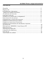
English


Contents
Warranty ........................................................................................... 2
Repair............ ..................................................................................... 2
Introduction ....................................................................................... 4
Transport and Storage ...................................................................... 5
Safety...... ...... ..................................................................................... 5
Appropriate Usage ........................................................................... 6
Feature Diagram ............................................................................... 6
Operation .......................................................................................... 7
Preparation and Safety Measures .................................................... 7
Current Measurements ..................................................................... 8
Voltage Measurements ..................................................................... 9
Resistance Measurements / Continuity ............................................ 10
MIN/MAX and Peak Values/ Auto Power Off ................................... 10
Maintenance ...................................................................................... 11
Changing the Battery ........................................................................ 11
Calibration Interval ........................................................................... 11
Specifications .................................................................................... 12
Certificate of Quality ........................................................................ 13
1
AC50A Leakage Clamp Meter

2
Limited Warranty and Limitation of Liability
Your Amprobe/Beha-Amprobe product will be free from defects in
material and workmanship for one year from the date of purchase
unless local laws require otherwise. This warranty does not cover
fuses, disposable batteries or damage from accident, neglect, misuse,
alteration, contamination, or abnormal conditions of operation or
handling. Resellers are not authorized to extend any other warranty
on the behalf of Amprobe/Beha-Amprobe. To obtain service during
the warranty period, return the product with proof of purchase to an
authorized Amprobe/Beha-Amprobe Service Center or to an Amprobe/
Beha-Amprobe dealer or distributor. See Repair Section for details.
THIS WARRANTY IS YOUR ONLY REMEDY. ALL OTHER WARRANTIES
- WHETHER EXPRESS, IMPLIED OR STATUTORY - INCLUDING
IMPLIED WARRANTIES OF FITNESS FOR A PARTICULAR PURPOSE OR
MERCHANTABILITY, ARE HEREBY DISCLAIMED. MANUFACTURER
SHALL NOT BE LIABLE FOR ANY SPECIAL, INDIRECT, INCIDENTAL OR
CONSEQUENTIAL DAMAGES OR LOSSES, ARISING FROM ANY CAUSE
OR THEORY. Since some states or countries do not allow the exclusion
or limitation of an implied warranty or of incidental or consequential
damages, this limitation of liability may not apply to you.
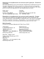
Repair
All Amprobe/Beha-Amprobe returned for warranty or non-warranty
repair or for calibration should be accompanied by the following:
your name, company’s name, address, telephone number, and proof
of purchase. Additionally, please include a brief description of the
problem or the service requested and include the test leads with
the meter. Non-warranty repair or replacement charges should be
remitted in the form of a check, a money order, credit card with
expiration date, or a purchase order made payable to Amprobe/Beha-
Amprobe.
In-Warranty Repairs and Replacement – All Countries
Please read the warranty statement and check your battery before
requesting repair. During the warranty period, any defective test
tool can be returned to your Amprobe/Beha-Amprobe distributor for
an exchange for the same or like product. Please check the “Where
to Buy” section on amprobe.com or beha-amprobe.com for a list of
distributors near you. Additionally, in the United States and Canada,
in-warranty repair and replacement units can also be sent to an
Amprobe/Beha-Amprobe Service Center (see address below).Service
Center (see address below).

Non-warranty Repairs and Replacement – United States and Canada
Non-warranty repairs in the United States and Canada should be sent
to an Amprobe Service Center. Call Amprobe or inquire at your point
of purchase for current repair and replacement rates.
USA: Canada:
Amprobe Amprobe
Everett, WA 98203 Mississauga, ON L4Z 1X9
Tel: 877-AMPROBE (267-7623) Tel: 905-890-7600
Non-Warranty Repairs and Replacement – Europe
European non-warranty units can be replaced by your Beha-Amprobe
distributor for a nominal charge. Please check the “Where to Buy” section
on beha-amprobe.com for a list of distributors near you.
Beha-Amprobe
Division and reg. trademark of Fluke Corp. (USA)
Germany* United Kingdom
In den Engematten 14 52 Hurricane Way
79286 Glottertal Norwich, Norfolk
Germany NR6 6JB United Kingdom
Phone: +49 (0) 7684 8009 - 0 Phone: +44 (0) 1603 25 6662
beha-amprobe.de beha-amprobe.com
The Netherlands - Headquarters**
Science Park Eindhoven 5110
5692 EC Son
The Netherlands
Phone: +31 (0) 40 267 51 00
beha-amprobe.com
*(Correspondence only – no repair or replacement available from this address.
European customers please contact your distributor.)
**single contact address in EEA Fluke Europe BV
3

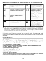
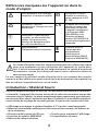
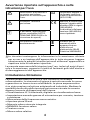
References marked on instrument or in user manual
Warning of a potential
danger, comply with users
manual.
Equipment protected
throughout by double
insulation or reinforced
insulation.
Caution! Dangerous voltage.
Danger of electrical shock.
Conformity symbol, the
instrument complies
with the valid directives.
It complies with the
EMC Directive (2014/30/
EU) and the Low
Voltage Directive
(2014/35/EU) with their
valid standards.
Caution: Risk of Electric
Shock
Reference. Please use
utmost attention.
Symbol for the
marking of electrical
and electronic
equipment (WEEE
Directive 2002/96/EC).
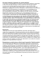
The user manual contains information and references, necessary for
safe operation and maintenance of the instrument. Prior to using the
instrument the use is kindly requested to thoroughly read the users
manual and comply with it in all sections.
Failure to read the user manual or to comply with the warnings and
references contained herein can result in serious bodily injury or instrument
damage
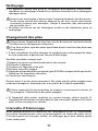
Introduction
The AC50A is a universal, multi-purpose electrical measuring instrument.
It comply with the standards DIN VDE 0411 and EN 61010, and provide
safe, reliable operation. The Current Clamp is a valuable tool for all sorts
of measurements in both trade and industry.
• 3
3
/4 digit liquid-crystal display
• Manual range selection for current, voltage, resistance measurements
• Clamp opening 30 mm (1/2 inch)
• Switches off automatically
• Integral memory for readings
• Evaluates MIN/MAX values
• Zero-setting
• Relative value function
The AC50A is supplied complete with leads. After unpacking, check that the
instrument is complete and that all accessories are present.
4

Contents:
1 Current Clamp AC50A
2 Test leads with probes (red/black)
2 Batteries 1,5V IEC LR6
1 Carrying case
1 User manual
Transport and Storage
• Please keep the original packaging for later transport, e.g. for calibration.
Any transport damage due to faulty packaging will be excluded from
warranty claims.
• In order to avoid instrument damage, it is advised to remove batteries
when not using the instrument over a certain time period. However,
should the instrument be contaminated by leaking battery cells, you are
kindly requested to return it to the factory for cleaning and inspection.
• Instruments must be stored in dry and closed areas. In the case of an
instrument being transported in extreme temperatures, a recovery time
of minimum 2 hours is required prior to instrument operation.
Safety
The Meter complies with:
- IEC/EN 61010-1:2010 Third edition to Measurement Category III
300 V and Measurement Category II 600 V, Pollution Degree 2
- IEC/EN 61010-2-030
- IEC/EN 61010-031 for test leads
- IEC/EN 61010-2-032
- EMC meets all applicable requirements in IEC/EN 61326-1
• The AC50A has been manufactured and tested to comply with the
safety regulations for electronic measuring equipment contained in
IEC61010 and EN 61010, and left the factory in a safe condition. To
maintain this condition, the user must observe the safety instructions
contained in this users manual.
• To avoid electric shock, safety measures must be observed when working
with voltages higher than 60V DC or 30 V RMS (42.4 V peak).
• Before each measurement make sure that the test leads and the
instrument are undamaged.
• Only handle test leads and probes on the grips provided. Avoid
touching probes under any circumstances.
• Measurements in dangerous proximity of electrical installations are
only to be executed when instructed by a responsible electrical
specialist, and never alone.
• The relevant safety regulations for electrical plant and equipment
must be observed during all operations.
• The instrument must only be used in the specified ranges.
• Before opening the instrument, it must be disconnected from all circuits.
• Protect the instrument from prolonged exposure to direct sunlight.
5

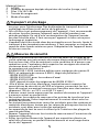
Appropriate Usage
• The instrument may only be used under the conditions and purposes
for which it was conceived. For this reason, in particular the safety
references, the technical data including environmental conditions
and the usage in dry environments must be followed.
• If the instrument is modified in any way, operational safety is no
longer ensured.
• The instrument may only be opened by an authorized service
technician, e.g. for fuse replacement.
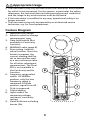
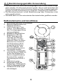
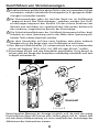
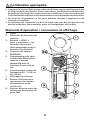
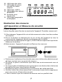
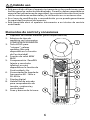
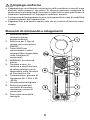
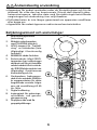
Feature Diagram
1. Induction coil (clamp)
2. Selector switch to change
measurement type
3. Data hold button (Not
available in Continuity
function)
4. MIN/MAX value (page 8)
5. Zero setting / relative
value function. Once this
button is pressed, the
current reading shall be
set to zero and be used
as a zero reference value
for all other subsequent
measurement. The Zero/
REL is not available in
the Continuity and Hz
function.
6. Frequency range select
switch. At 50/60Hz
position, only the low
frequency signal is
measured. At Wide
position, signal from 40 -
1kHz is measured.
7. Digital display
8. Input socket, for
measuring voltage,
resistance, continuity
testing
9. Hand-hold area including
barrier (9a)
6

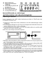
10. Low-battery symbol
11. Zero Point / Relative Value
symbol
12. Hold symbol (Data Hold
is active)
13. Min/Max symbol
14. Continuity symbol
15. Analog bargraph
Operation
Preparation and safety measures
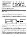
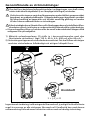
Installing the battery
Before using the instrument, the battery must be installed. This is carried
out as follows:
1) Separate the instrument from any circuit, and remove the test leads.
2) Open the housing by removing the screw on the rear face.
3) Fit the new batteries (2 type 1.5 V IEC LR6), taking care that the polarity
is correct. Make sure that no wires are trapped between the 2 halves
of the housing and close.
4) The instrument is now ready for use.
• The selector switch must be turned to the desired type of measurement
before the probes are connected to the unit under test (UUT).
• Before switching to a new function, the probes must always be removed
from the UUT.
• Use the instrument only in clean and dry surroundings. Dirt and moisture
reduce the effectiveness of the insulation, with consequent danger of
electric shock, especially when dealing with high voltages.
• Use the instrument only in the specified ranges. Before making
measurements, verify that the instrument is functioning properly, for
example by testing on a known voltage or current. Make sure that the
test leads are undamaged.
7
10
11
12
13 14
15

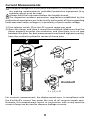
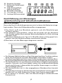
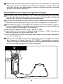
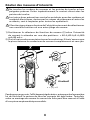
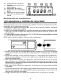
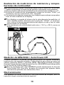
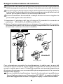
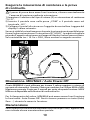
Current Measurements
If tangible dangerous active parts are present in the plant where you
are making measurements, individual protection equipment (e.g.
suitable covers) must be used.
Always hold the instrument below the handle shroud.
The respective accident prevention regulations established by the
professional associations are to be strictly enforced at all times regarding
tasks executed under voltage or in proximity of parts under voltage.
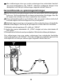
1) Turn selector switch (2) to the AC current range you need
2) Open the clamp, and close it round the conductor. Make sure that the
clamp properly encircles the conductor, and that there is no air gap
between the jaws. For best measurement results and highest accuracy,
have the conductor placed in center of clamp jaws.
For incorrect measurement, the display equals zero. In compliance with
the Kirchhoff’s current law states the sum of all currents equals zero.
However, this measurement layout in conjunction with a very sensitive
current clamp can be used to measure leakage currents.
8
I
I
OK
OK
OK
I + (- I) = 0
I
40
mA
4
A
60
A
40
A
OFF
ZER
O
MIN/
MAX
HOL
D
COM
0 10 20 30 40
600
V
AC
400
mA
Kirchhoff

If the display is not visible during measurement, press the “HOLD”
button (3) to retain the display. The clamp can then be removed from
the conductor and the stored value read.
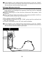
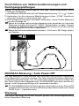
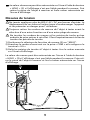
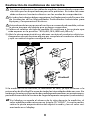
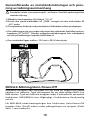
Voltage Measurements
Do not connect more than 600 V AC / DC to the input sockets. Exceeding
these values can endanger the operator, and may result in damage
to the instrument.
Before switching to a new function, disconnect the probes from
the UUT.
Only handle test leads and probes on the grips provided. Avoid tou-
ching the probes under any circumstances.
1) Turn selector switch (2) to 400
2) Plug the black test lead into the “COM” socket and the red lead into
the “VΩ” terminal
3) Connect the probes to the UUT and read the display
If the display is not visible during measurement, press the “HOLD”
button (3) to retain the display. The probes can then be removed from
the conductor and the stored value read.
9
40
mA
4
A
60
A
40
A
OFF
ZERO
MIN/M
A
X
HOLD
COM
0 10 20 30 40
600
V
AC
400
mA

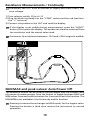
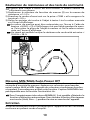
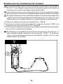
Resistance Measurements / Continuity
Disconnect the UUT from all sources of supply and check that it is at
zero voltage.
1) Turn selector switch (2) to Ω /
2) Plug the black test lead into the “COM” socket and the red lead into
the “+” terminal
3) Connect the probes to the UUT and read the display
If the display is not visible during measurement, press the “HOLD”
button (3) to retain the display. The probes can then be removed from
the conductor and the stored value read.
Continuity: At a resistance between ≤ 10 Ω and > 38 Ω a signal is audible.
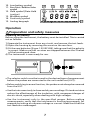
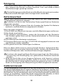
MIN/MAX and peak values/ Auto Power Off
The MIN/MAX button can be used to find the largest and the smallest value
of a series of measurements. Press the button to toggle between MAX and
MIN values. Press and hold the button for 2 seconds to exit this function. The
MAX/MIN is not available in the Continuity and Hz function.
Pressing it a second time changes to MAX mode, for the largest value.
Pressing the button a third time returns the instrument to normal
operation.
10
40
mA
4
A
60
A
40
A
OFF
ZERO
MIN/M
A
X
HOLD
COM
0 10 20 30 40
600
V
AC
400
mA

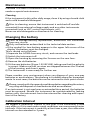
Maintenance
Provided it is used in accordance with the user manual, the instrument
needs no special maintenance.
Cleaning
If the instrument is dirty after daily usage, clean it by using a humid cloth
and a mild household detergent.
Prior to cleaning, ensure that instrument is switched off and dis-
connected from external voltage supply and any other instruments
connected (such as UUT, control instruments, etc.).
Never use acid detergents or dissolvents for cleaning.
Changing the battery
Prior to storage battery replacement, disconnect the instrument
from any circuits.
Only use batteries as described in the technical data section.
• If the symbol for Low-battery appears in the upper left corner of the
display, the battery must be changed.
This is carried out as follows:
1) Separate the AC50A from any circuit, and remove the test leads.
2) Switch the instrument off.
3) Open the housing by removing the 3 screws on the rear face.
4) Remove the old batteries.
5) Fit the new batteries (2 type 1.5 V IEC LR6), taking care that the polarity
is correct. Make sure that no wires are trapped between the 2 halves
of the housing, and close it again.
6) The instrument is now ready for further use.
Please consider your environment when you dispose of your one-way
batteries or accumulators. They belong in a rubbish dump for hazardous
waste. In most cases, the batteries can be returned to their point of sale.
Please, comply with the respective valid regulation regarding the return,
recycling and disposal of used batteries and accumulators.
If an instrument is not used over an extended time period, the batteries
must be removed. Should the instrument be contaminated by leaking
battery cells, the instrument has to be returned for cleaning and inspec-
tion to the factory.
Calibration Interval
We suggest a calibration interval of one year. If the instrument is used
very often or if it is used under rough conditions we recommend shorter
intervals. If the instrument is used only a few times a year, the calibration
interval can be extended to 3 years.
11

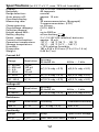
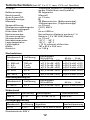
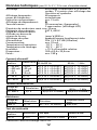
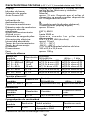
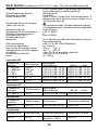
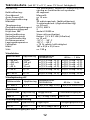
Specifications (at 23 °C ± 5 °C, max. 75% rel. humidity)
Display: 3
3
/4, LCD incl. functions and symbols
Bargraph: 40 segments
Range selection: manual
Auto power-off: approx. 15 min.
Overload display:
Measuring rate: 30 measurements/sec. (Bargraph)
3 measurements/sec. (LCD)
Clamp opening: ca. 30 mm
Overvoltage category: CAT II, 600 V
Pollution degree: 2
Height above MSL.: up to 2000 m
Battery display: at low battery
Power supply: 2 x 1,5 V IEC LR6 (alkaline) batteries
Current consumption: approx. 10 mA
Operation temperature: -10 °C … 50 °C (14 °F … 122 °F)
Storage temperature: -20 °C … 60 °C (-4 °F … 140 °F)
Humidity: < 75% relative humidity
Dimension: 183 x 63.6 x 35.6 mm (7.2 x 2.5 x 1.4 in)
Weight: 0.44 lb (7 oz)
Current AC
Range Resolution
Accuracy
50 Hz/60 Hz 40 Hz … 1 kHz
0 – 40 mA
0 – 400 mA
0 – 4 A
0 – 40 A
10 µA
100 µA
1 mA
10 mA
±(1,5 % rdg. +3 D) ±(2,0 % rdg. +5 D)
0 – 50 A 0,1 A ±(1,5 % rdg. +5 D) ±(2,0 % rdg. +5 D)
50 – 60 A 0,1 A ±(3,0 % rdg. +5 D) ±(3,5 % rdg. +5 D)
Voltage AC
Range Resolution
Accuracy
50 Hz/60 Hz 40 Hz … 1 kHz
0...400 V 0,1 Ω ±(1,0 % rdg. +3 D) ±(2,0 % rdg.± 4 D)
Resistance
Range Resolution Accuracy Overload Protection
400 Ω 0,1 Ω ±(1 % rdg. +3 D) 600 V AC
Continuity
Range Resolution Beep Open Circuit Voltage
Ω /
0,1 Ω ON ≤ 10 Ω; OFF > 38 Ω < 0,4 V
Overload Protection 600 V AC
12

Certificate of Quality
Beha-Amprobe (a division of Fluke Corp. USA) confirms herein
that the unit you have purchased has been calibrated, during the
manufacturing process, in compliance with the test procedures
defined by Beha-Amprobe. All Beha-Amprobe procedures
and quality controls are monitored on a permanent basis in
compliance with the ISO 9000 Quality Management Standards.
In addition, Beha-Amprobe confirms that all test equipment and
instruments used during the calibration process are subject to
constant control. All test equipment and instruments used are
calibrated at determined intervals, using reference equipment
which has also been calibrated in compliance with (and traceable
to) the calibration standards of national and international
laboratories.
Beha-Amprobe
Division and reg. trademark of Fluke Corp. (USA)
Germany United Kingdom
In den Engematten 14 52 Hurricane Way
79286 Glottertal Norwich, Norfolk
Germany NR6 6JB United Kingdom
Phone: +49 (0) 7684 8009 - 0 Phone: +44 (0) 1603 25 6662
beha-amprobe.de beha-amprobe.com
The Netherlands - Headquarters
Science Park Eindhoven 5110
5692 EC Son
The Netherlands
Phone: +31 (0) 40 267 51 00
beha-amprobe.com
13


Deutsch
AC50A
Leckstromzange
Bedienungshandbuch
5/2018, Rev.B
©2018 Amprobe.
Alle Rechte vorbehalten. In Taiwan gedruckt

La page est en cours de chargement...
La page est en cours de chargement...
La page est en cours de chargement...
La page est en cours de chargement...
La page est en cours de chargement...
La page est en cours de chargement...
La page est en cours de chargement...
La page est en cours de chargement...
La page est en cours de chargement...
La page est en cours de chargement...
La page est en cours de chargement...
La page est en cours de chargement...
La page est en cours de chargement...
La page est en cours de chargement...
La page est en cours de chargement...
La page est en cours de chargement...
La page est en cours de chargement...
La page est en cours de chargement...
La page est en cours de chargement...
La page est en cours de chargement...
La page est en cours de chargement...
La page est en cours de chargement...
La page est en cours de chargement...
La page est en cours de chargement...
La page est en cours de chargement...
La page est en cours de chargement...
La page est en cours de chargement...
La page est en cours de chargement...
La page est en cours de chargement...
La page est en cours de chargement...
La page est en cours de chargement...
La page est en cours de chargement...
La page est en cours de chargement...
La page est en cours de chargement...
La page est en cours de chargement...
La page est en cours de chargement...
La page est en cours de chargement...
La page est en cours de chargement...
La page est en cours de chargement...
La page est en cours de chargement...
La page est en cours de chargement...
La page est en cours de chargement...
La page est en cours de chargement...
La page est en cours de chargement...
La page est en cours de chargement...
La page est en cours de chargement...
La page est en cours de chargement...
La page est en cours de chargement...
La page est en cours de chargement...
La page est en cours de chargement...
La page est en cours de chargement...
La page est en cours de chargement...
La page est en cours de chargement...
La page est en cours de chargement...
La page est en cours de chargement...
La page est en cours de chargement...
La page est en cours de chargement...
La page est en cours de chargement...
La page est en cours de chargement...
La page est en cours de chargement...
La page est en cours de chargement...
La page est en cours de chargement...
La page est en cours de chargement...
La page est en cours de chargement...
La page est en cours de chargement...
La page est en cours de chargement...
La page est en cours de chargement...
La page est en cours de chargement...
La page est en cours de chargement...
La page est en cours de chargement...
La page est en cours de chargement...
La page est en cours de chargement...
La page est en cours de chargement...
La page est en cours de chargement...
La page est en cours de chargement...
La page est en cours de chargement...
La page est en cours de chargement...
La page est en cours de chargement...
-
 1
1
-
 2
2
-
 3
3
-
 4
4
-
 5
5
-
 6
6
-
 7
7
-
 8
8
-
 9
9
-
 10
10
-
 11
11
-
 12
12
-
 13
13
-
 14
14
-
 15
15
-
 16
16
-
 17
17
-
 18
18
-
 19
19
-
 20
20
-
 21
21
-
 22
22
-
 23
23
-
 24
24
-
 25
25
-
 26
26
-
 27
27
-
 28
28
-
 29
29
-
 30
30
-
 31
31
-
 32
32
-
 33
33
-
 34
34
-
 35
35
-
 36
36
-
 37
37
-
 38
38
-
 39
39
-
 40
40
-
 41
41
-
 42
42
-
 43
43
-
 44
44
-
 45
45
-
 46
46
-
 47
47
-
 48
48
-
 49
49
-
 50
50
-
 51
51
-
 52
52
-
 53
53
-
 54
54
-
 55
55
-
 56
56
-
 57
57
-
 58
58
-
 59
59
-
 60
60
-
 61
61
-
 62
62
-
 63
63
-
 64
64
-
 65
65
-
 66
66
-
 67
67
-
 68
68
-
 69
69
-
 70
70
-
 71
71
-
 72
72
-
 73
73
-
 74
74
-
 75
75
-
 76
76
-
 77
77
-
 78
78
-
 79
79
-
 80
80
-
 81
81
-
 82
82
-
 83
83
-
 84
84
-
 85
85
-
 86
86
-
 87
87
-
 88
88
-
 89
89
-
 90
90
-
 91
91
-
 92
92
-
 93
93
-
 94
94
-
 95
95
-
 96
96
-
 97
97
-
 98
98


Amprobe AC50A Leakage Clamp Meter Manuel utilisateur
- Taper
- Manuel utilisateur
dans d''autres langues
Documents connexes
-
Amprobe CR50A Manuel utilisateur
-
Amprobe ACDC-400 Manuel utilisateur
-
-
-
-
-
Amprobe ALC-110 Leakage Clamp Manuel utilisateur
-
-
Amprobe TMA10A Manuel utilisateur
-
Autres documents
-
Wavetek AC50 Mode d'emploi
-
Fluke Calibration 9640A Manuel utilisateur
-
POWERFIX KH 3322 Le manuel du propriétaire
-
Fluke Juego de sondas de prueba con fusibles TLK291 de Manuel utilisateur
-
-
PeakTech 1650 Le manuel du propriétaire
-
Benning DUTEST Manuel utilisateur
-
Fluke Calibration 6270A Manuel utilisateur
-
-
TESTBOY TV 218 Manuel utilisateur