Amprobe CR50A Manuel utilisateur
- Catégorie
- Multimètres
- Taper
- Manuel utilisateur

CR50A
Capacitance,
Resistance Meter
User Manual
ENG FRE
SPA
Cx Rx
DISCHARGE CAPACITOR
BEFORE CONNECTING


CR50A
Capacitance,
Resistance Meter
User Manual
6/2018, 6010985 B
©2018 Amprobe.
All rights reserved. Printed in Taiwan
English

Limited Warranty and Limitation of Liability
Your Amprobe product will be free from defects in material and
workmanship for one year from the date of purchase unless
local laws require otherwise. This warranty does not cover
fuses, disposable batteries or damage from accident, neglect,
misuse, alteration, contamination, or abnormal conditions
of operation or handling. Resellers are not authorized to
extend any other warranty on the behalf of Amprobe. To
obtain service during the warranty period, return the product
with proof of purchase to an authorized Amprobe Service
Center or to an Amprobe dealer or distributor. See Repair
Section for details. THIS WARRANTY IS YOUR ONLY REMEDY.
ALL OTHER WARRANTIES - WHETHER EXPRESS, IMPLIED OR
STATUTORY - INCLUDING IMPLIED WARRANTIES OF FITNESS FOR
A PARTICULAR PURPOSE OR MERCHANTABILITY, ARE HEREBY
DISCLAIMED. MANUFACTURER SHALL NOT BE LIABLE FOR ANY
SPECIAL, INDIRECT, INCIDENTAL OR CONSEQUENTIAL DAMAGES
OR LOSSES, ARISING FROM ANY CAUSE OR THEORY. Since some
states or countries do not allow the exclusion or limitation of an
implied warranty or of incidental or consequential damages, this
limitation of liability may not apply to you.
Repair
All Amprobe returned for warranty or non-warranty repair or
for calibration should be accompanied by the following: your
name, company’s name, address, telephone number, and proof
of purchase. Additionally, please include a brief description of
the problem or the service requested and include the test leads
with the meter. Non-warranty repair or replacement charges
should be remitted in the form of a check, a money order, credit
card with expiration date, or a purchase order made payable
to Amprobe.
In-Warranty Repairs and Replacement – All Countries
Please read the warranty statement and check your battery
before requesting repair. During the warranty period,
any defective test tool can be returned to your Amprobe
distributor for an exchange for the same or like product. Please
check the “Where to Buy” section on amprobe.com for a list
of distributors near you. Additionally, in the United States and
Canada, in-warranty repair and replacement units can also be
sent to an Amprobe Service Center (see address below).

Non-warranty Repairs and Replacement
– United States and Canada
Non-warranty repairs in the United States and Canada
should be sent to an Amprobe Service Center. Call
Amprobe or inquire at your point of purchase for current
repair and replacement rates.
USA: Canada:
Amprobe Amprobe
Everett, WA 98203 Mississauga, ON L4Z 1X9
Tel: 877-AMPROBE (267-7623) Tel: 905-890-7600
Non-Warranty Repairs and Replacement – Europe
European non-warranty units can be replaced by your Beha-
Amprobe distributor for a nominal charge. Please check the
“Where to Buy” section on beha-amprobe.com for a list of
distributors near you.
Beha-Amprobe
Division and reg. trademark of Fluke Corp. (USA)
Germany* United Kingdom
In den Engematten 14 52 Hurricane Way
79286 Glottertal Norwich, Norfolk
Germany NR6 6JB United Kingdom
Phone: +49 (0) 7684 8009 - 0 Phone: +44 (0) 1603 25 6662
beha-amprobe.de beha-amprobe.com
The Netherlands - Headquarters**
Science Park Eindhoven 5110
5692 EC Son
The Netherlands
Phone: +31 (0) 40 267 51 00
beha-amprobe.com
*(Correspondence only – no repair or replacement
available from this address. European customers please
contact your distributor.)
**single contact address in EEA Fluke Europe BV

CR50A Capacitance, Resistance Meter
Cx
200
n
20m
200p
200
ZERO
ADJUST
(20 )
OFF
20
2k
2M
20M
CR50
F
20
k
200
k
2m
200
20
2
20n
2n
CAP.
ZERO
ADJUST
Rx
DISCHARGE CAPACITOR
BEFORE CONNECTING
nF
pF
F
MF
3
2
1
4 6
5
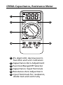
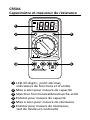
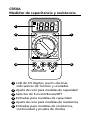
1
3½ digit LCD; decimal point,
function and unit indicators
2
Capacitance Zero Adjustment
3
Function/Range/Off Selector
4
Capacitance Input Terminals
5
Resistance Zero Adjustment
6
Input Terminals for resistance,
diode test and continuity

1
CR50A Capacitance, Resistance Meter
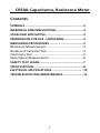
Contents
SYMBOLS ....................................................................2
WARNINGS AND PRECAUTIONS............ ....................2
OVERLOAD INDICATION ............................................3
PREPARATION FOR USE - UNPACKING .......................3
MEASURING PROCEDURES ........................................3
Resistance Measurement ...........................................4
Diode and Transistor Test ...........................................5
Continuity Test............................................................6
Capacitance Measurement ........................................6
SAFETY TEST LEADS ...................................................7
SPECIFICATIONS ..........................................................8
ELECTRICAL SPECIFICATIONS .....................................10
TROUBLESHOOTING/MAINTENANCE ........................12

2
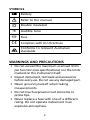
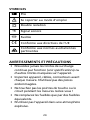
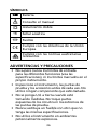
SYMBOLS
Battery
Refer to the manual
Double insulated
Audible tone
Fuse
Complies with EU directives
Conforms to relevant Australian
standards
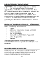
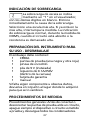
WARNINGS AND PRECAUTIONS
• Do not exceed the maximum overload limits
per function (see specifications) nor the limits
marked on the instrument itself.
• Inspect instrument, test leads and accessories
before every use. Do not use any damaged part.
• Never ground yourself when taking
measurements.
• Do not touch exposed circuit elements or
probe tips.
• Never replace a fuse with one of a different
rating. Do not operate instrument in an
explosive atmosphere.

3
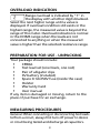
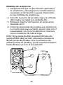
OVERLOAD INDICATION
Range overload is indicated by “1” in
the display with all other digits blanked.
Select the next higher range until a value is
displayed. If overload condition still exists in the
highest range, the measured value is beyond the
range of the meter. Overload indication is normal
in the OHMS range when the leads are not
connected to anything or when the measured
value is higher than the selected resistance range.
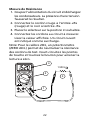
PREPARATION FOR USE - UNPACKING
Your package should include:
1 CR50A
1 Test lead set (one black, one red)
1 Pair of alligator clips
1 9V battery (installed)
1 Spare 0.1A/250V fuse (inside the case)
1 Holster
1 Warranty Card
1 User manual
If any item is damaged or missing, return to the
place of purchase for an exchange.
MEASURING PROCEDURES
General: When connecting or disconnecting test leads
to/from a circuit, always first turn off power to device
or circuit being tested and discharge all capacitors.

4
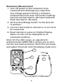
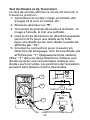
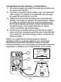
Resistance Measurement
1. Turn off power to the resistance to be
measured and discharge any capacitors.
Any voltage present during a resistance
measurement will cause inaccurate readings.
Connect red test lead to +Rx Input (red) and
black test lead to -Rx Input.
2. Set Function/Range Switch to the desired
Ω position.
3. Connect test leads to resistance or circuit to
be measured.
4. Read resistance value on Digital Display.
Open circuits will be displayed as an
overload condition.
Note: On the 20Ω range, an adjustment
potentiometer (ZERO ADJ.) allows you to zero
out the test lead resistance. Short the test leads
and adjust the knob until the display reads zero.
Cx
200
n
20m
200p
200
ZERO
ADJUST
(20 )
OFF
20
2k
2M
20M
CR50
F
20
k
200
k
2m
200
20
2
20n
2n
CAP.
ZERO
ADJUST
Rx
DISCHARGE CAPACITOR
BEFORE CONNECTING
1.520 k
4
3
2
1

5
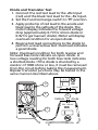
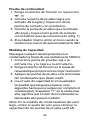
Diode and Transistor Test
1. Connect the red test lead to the +Rx Input
(red) and the black test lead to the –Rx Input.
2. Set the Function/range switch to
d
position.
3. Apply probe tip of red lead to the anode and
black lead to the cathode of the diode. The
meter’s display indicates the forward voltage
drop (approximately 0.7V for silicon diode or
0.4V for germanium diode). Meter will display
overload condition for an open diode.
4. Reverse test lead connections to the diode to
perform a reverse bias test. Overload indicates
a good diode.
Note: Overload condition for both reverse and
forward bias tests indicate an open diode. A
low voltage reading for both bias tests indicates
a shorted diode. If the diode is shunted by a
resistor of 1000 ohms or less, it must be removed
from the circuit before taking the measurement.
Bipolar transistor junctions may be tested in the
same manner described above.
Cx
200
n
20m
200p
200
ZERO
ADJUST
(20 )
OFF
20
2k
2M
20M
CR50
F
20
k
200
k
2m
200
20
2
20n
2n
CAP.
ZERO
ADJUST
Rx
DISCHARGE CAPACITOR
BEFORE CONNECTING
Cathode Anode
Cathode
600 - 900 mV
<1 V
Anode
4
3
2
1
OK
OK
OK
OK

6
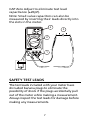
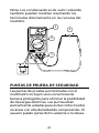
Continuity Test
The Continuity test checks electrical continuity
between two contact points.
1. Set the Function/Range switch to
d
.
2. Plug the black test lead into the –Rx jack
(black) and connect the test lead tip to one of
the contact points
3. Plug the red test lead into the +Rx jack (red)
and connect its test lead point to the other
contact point. (See Figure 1 for connections)
4. The internal beeper emits a tone when
resistance is less than approx. 40Ω
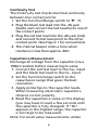
Capacitance Measurement
Discharge all voltage from the capacitor (via a
100kΩ resistor) before measuring its value
1. Connect the red test lead to the Cx+ input
and the black test lead to the Cx– input.
2. Set the function/range switch to the
capacitance range that gives the best
resolution.
3. Apply probe tips to the capacitor leads.
When measuring electrolytic capacitors,
observe correct polarity.
4. Read the capacitance value on the display
(you may have to wait a few seconds until
the capacitor is fully charged). If “OL”
appears in the highest range, the capacitor
is too large to be measured.
Note: For small value measurements utilize

7
CAP Zero Adjust to eliminate test lead
capacitance (±20pF).
Note: Small value capacitors can also be
measured by inserting their leads directly into
the slots in the meter.
Cx
200
n
20m
200p
200
ZERO
ADJUST
(20 )
OFF
20
2k
2M
20M
CR50
F
20
k
200
k
2m
200
20
2
20n
2n
CAP.
ZERO
ADJUST
Rx
DISCHARGE CAPACITOR
BEFORE CONNECTING
F
1
3
2
4
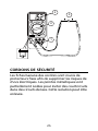
SAFETY TEST LEADS
The test leads included with your meter have
shrouded banana plugs to eliminate the
possibility of shock if the plugs accidentally pull
out of the meter while making a measurement.
Always inspect the test leads for damage before
making any measurements.

8
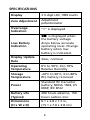
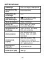
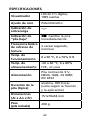
SPECIFICATIONS
Display
3 ½ digit LCD, 1999 counts
Zero Adjustment
Adjustment
potentiometer
Overrange
Indication
“1” is displayed
Low Battery
Indication
is displayed when
the battery voltage
drops below accurate
operating level. Change
battery when low
battery is indicated.
Display Update
Rate
2/sec, nominal
Operating
Temperature
0°C to 50°C, 0 to 70%
Relative Humidity
Storage
Temperature
-20°C to 60°C, 0 to 80%
RH, battery removed
Power
Standard 9V transistor
battery, NEDA 1604, JIS
006P, IEC 6F22
Battery Life
(Typical)
200 hours alkaline, 150
hours carbon-zinc
Dimensions
(H x W x D)
6.1 x 2.8 x 1.3 in,
(15.1 x 7.0 x 3.8 cm)

9
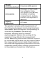
Weight
(including battery)
8 ounces (200 grams)
Accessories
One pair of test leads,
two alligator clips,
one spare fuse (FP125)
installed in battery
compartment, battery,
holster and Operator’s
Manual.
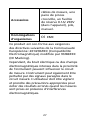
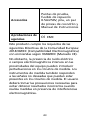
Agency
Approvals
EMC
This product complies with requirements of
the following European Community Directives:
2014/30/EEC (Electromagnetic Compatibility) as
amended by 93/68/EEC (CE Marking).
However, electrical noise or intense
electromagnetic fields in the vicinity of the
equipment may disturb the measurement
circuit. Measuring instruments will also respond
to unwanted signals that may be present within
the measurement circuit. Users should exercise
care and take appropriate precautions to avoid
misleading results when making measurements
in the presence of electronic interference.

10
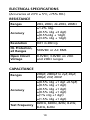
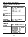
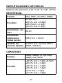
ELECTRICAL SPECIFICATIONS
(Accuracies at 23°C ± 5°C, <75% RH.)
RESISTANCE
Ranges 20Ω, 200Ω, 2k-2MΩ, 20MΩ
Accuracy
±1.2% rdg.
±(0.5% rdg +3 dgt)
±(0.5%rdg + 1dgt)
±(3.0% rdg + 1dgt)
Resolution 0.01 in 20Ω rg.
OL Protection,
all Ranges
500VDC or AC RMS
Open Circuit
Voltage
0.3VDC; 3.0VDC on 20Ω
and 200Ω ranges
CAPACITANCE
Ranges
200pF, 2000pF to 2μF, 20μF,
200μF, 2mF, 20mF
Accuracy
±(0.5% rdg +1 dgt +0.5pF)
±(0.5% rdg +1 dgt)
±(0.5% rdg +1 dgt)
±(0.5% rdg +1 dgt)
±(1% rdg +1 dgt)
±(1.5% rdg +1 dgt)
Test Frequency
820Hz, 820Hz, 82Hz, 8.2Hz,
8.2Hz, 8.2Hz

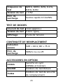
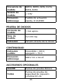
11
Test Voltage < 3.5V
Input
Protection
0.1A/250V Fast Acting Fuse
DIODE TEST
Test Current/
Voltage
1mA (approx.) / 3.2VDC
Display Forward Junction Voltage
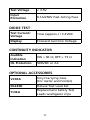
CONTINUITY INDICATOR
Audible
Indication
ON ≤ 40 Ω; OFF > 75 Ω
OL Protection 500VDC or AC
OPTIONAL ACCESSORIES
VC30A
Vinyl Carrying Case
(for meter and holster)
DL243D Deluxe Test Lead Set
TL36A
Replacement Safety Test
Leads w/alligator clips

12
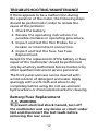
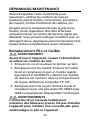
TROUBLESHOOTING/MAINTENANCE
If there appears to be a malfunction during
the operation of the meter, the following steps
should be performed in order to isolate the
cause of the problem:
1. Check the battery.
2. Review the operating instructions for
possible mistakes in operating procedure.
3. Inspect and test the Test Probes for a
broken or intermittent connection.
4. Inspect and test the fuse. See Fuse
Replacement.
Except for the replacement of the battery or fuse,
repair of the multimeter should be performed
only by a Factory Authorized Service Center or by
other qualified instrument service personnel.
The front panel and case can be cleaned with
a mild solution of detergent and water. Apply
sparingly with a soft cloth and allow to dry
completely before using. Do not use aromatic
hydrocarbons or chlorinated solvents for cleaning.
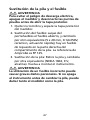
Battery/Fuse Replacement
WARNING
To prevent electrical shock hazard, turn off
the multimeter and any device or circuit under
test and disconnect the test leads before
removing the rear cover.

13
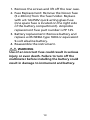
1. Remove the screws and lift off the rear case.
2. Fuse Replacement: Remove the blown fuse
(5 x 20mm) from the fuse holder. Replace
with a 0.1A/250V quick acting glass fuse
(one spare fuse is located on the right side
of the battery compartment). Amprobe
replacement fuse part number is FP 125.
3. Battery replacement: Remove battery and
replace with NEDA type 1604 or equivalent
9-volt alkaline battery.
4. Reassemble the instrument.
WARNING
Use of an incorrect fuse could result in serious
injury or even death. Failure to turn off the
multimeter before installing the battery could
result in damage to instrument and battery.

La page est en cours de chargement...
La page est en cours de chargement...
La page est en cours de chargement...
La page est en cours de chargement...
La page est en cours de chargement...
La page est en cours de chargement...
La page est en cours de chargement...
La page est en cours de chargement...
La page est en cours de chargement...
La page est en cours de chargement...
La page est en cours de chargement...
La page est en cours de chargement...
La page est en cours de chargement...
La page est en cours de chargement...
La page est en cours de chargement...
La page est en cours de chargement...
La page est en cours de chargement...
La page est en cours de chargement...
La page est en cours de chargement...
La page est en cours de chargement...
La page est en cours de chargement...
La page est en cours de chargement...
La page est en cours de chargement...
La page est en cours de chargement...
La page est en cours de chargement...
La page est en cours de chargement...
La page est en cours de chargement...
La page est en cours de chargement...
La page est en cours de chargement...
La page est en cours de chargement...
La page est en cours de chargement...
La page est en cours de chargement...
La page est en cours de chargement...
La page est en cours de chargement...
-
 1
1
-
 2
2
-
 3
3
-
 4
4
-
 5
5
-
 6
6
-
 7
7
-
 8
8
-
 9
9
-
 10
10
-
 11
11
-
 12
12
-
 13
13
-
 14
14
-
 15
15
-
 16
16
-
 17
17
-
 18
18
-
 19
19
-
 20
20
-
 21
21
-
 22
22
-
 23
23
-
 24
24
-
 25
25
-
 26
26
-
 27
27
-
 28
28
-
 29
29
-
 30
30
-
 31
31
-
 32
32
-
 33
33
-
 34
34
-
 35
35
-
 36
36
-
 37
37
-
 38
38
-
 39
39
-
 40
40
-
 41
41
-
 42
42
-
 43
43
-
 44
44
-
 45
45
-
 46
46
-
 47
47
-
 48
48
-
 49
49
-
 50
50
-
 51
51
-
 52
52
-
 53
53
-
 54
54


Amprobe CR50A Manuel utilisateur
- Catégorie
- Multimètres
- Taper
- Manuel utilisateur
dans d''autres langues
- español: Amprobe CR50A Manual de usuario
Documents connexes
-
Amprobe AC50A Leakage Clamp Meter Manuel utilisateur
-
-
-
Amprobe AC68C Le manuel du propriétaire
-
-
Amprobe Digital Multimeter AM-420 Manuel utilisateur
-
-
-
-