
User Manual
ENG FRE
SPA
38XR-A
Professional
Digital
Multimeter
38XR-A


38XR-A
Professional Digital
Multimeter
User Manual
5/2018, 6010932 C
©2018 Amprobe
All rights reserved. Printed in Taiwan
English

Limited Warranty and Limitation of Liability
Your Amprobe product will be free from defects in material and
workmanship for one year from the date of purchase unless
local laws require otherwise. This warranty does not cover fuses,
disposable batteries or damage from accident, neglect, misuse,
alteration, contamination, or abnormal conditions of operation or
handling. Resellers are not authorized to extend any other warranty
on the behalf of Amprobe. To obtain service during the warranty
period, return the product with proof of purchase to an authorized
Amprobe Service Center or to an Amprobe dealer or distributor.
See Repair Section for details. THIS WARRANTY IS YOUR ONLY
REMEDY. ALL OTHER WARRANTIES - WHETHER EXPRESS, IMPLIED
OR STATUTORY - INCLUDING IMPLIED WARRANTIES OF FITNESS
FOR A PARTICULAR PURPOSE OR MERCHANTABILITY, ARE HEREBY
DISCLAIMED. MANUFACTURER SHALL NOT BE LIABLE FOR ANY
SPECIAL, INDIRECT, INCIDENTAL OR CONSEQUENTIAL DAMAGES OR
LOSSES, ARISING FROM ANY CAUSE OR THEORY. Since some states
or countries do not allow the exclusion or limitation of an implied
warranty or of incidental or consequential damages, this limitation
of liability may not apply to you.
Repair
All Amprobe returned for warranty or non-warranty repair or
for calibration should be accompanied by the following: your
name, company’s name, address, telephone number, and proof of
purchase. Additionally, please include a brief description of the
problem or the service requested and include the test leads with
the meter. Non-warranty repair or replacement charges should be
remitted in the form of a check, a money order, credit card with
expiration date, or a purchase order made payable to Amprobe.
In-Warranty Repairs and Replacement – All Countries
Please read the warranty statement and check your battery before
requesting repair. During the warranty period, any defective
test tool can be returned to your Amprobe distributor for an
exchange for the same or like product. Please check the “Where
to Buy” section on amprobe.com for a list of distributors near you.
Additionally, in the United States and Canada, in-warranty repair
and replacement units can also be sent to an Amprobe Service
Center (see address below).

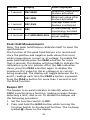
Non-warranty Repairs and Replacement – United States and Canada
Non-warranty repairs in the United States and Canada should be
sent to an Amprobe Service Center. Call Amprobe or inquire at
your point of purchase for current repair and replacement rates.
USA: Canada:
Amprobe Amprobe
Everett, WA 98203 Mississauga, ON L4Z 1X9
Tel: 877-AMPROBE (267-7623) Tel: 905-890-7600
Non-Warranty Repairs and Replacement – Europe
European non-warranty units can be replaced by your Beha-Amprobe
distributor for a nominal charge. Please check the “Where to Buy”
section on beha-amprobe.com for a list of distributors near you.
Beha-Amprobe
Division and reg. trademark of Fluke Corp. (USA)
Germany
* United Kingdom
In den Engematten 14 52 Hurricane Way
79286 Glottertal Norwich, Norfolk
Germany NR6 6JB United Kingdom
Phone: +49 (0) 7684 8009 - 0 Phone: +44 (0) 1603 25 6662
beha-amprobe.de beha-amprobe.com
The Netherlands - Headquarters
**
Science Park Eindhoven 5110
5692 EC Son
The Netherlands
Phone: +31 (0) 40 267 51 00
beha-amprobe.com
*(Correspondence only – no repair or replacement available from this address.
European customers please contact your distributor.)
**single contact address in EEA Fluke Europe BV

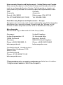
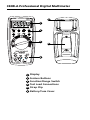
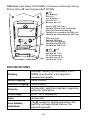
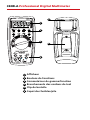
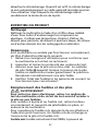
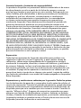
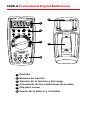
38XR-A Professional Digital Multimeter
1
Display
2
Feature Buttons
3
Function/Range Switch
4
Test Lead Connections
5
Strap Clip
6
Battery/Fuse Cover
38XR-A
MADE IN TAIWAN
PATENTS PENDING
www.amprobe.com
1
2
3
4
5
6

1
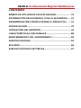
38XR-A Professional Digital Multimeter
CONTENTS
SYMBOLS ...................................................................... 2
SAFETY INFORMATION ................................................ 2
UNPACKING AND INSPECTION ....................................3
INTRODUCTION ............................................................4
MAKING MEASUREMENTS ..........................................4
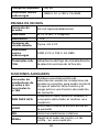
ADDITIONAL FEATURES ............................................... 16
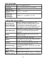
PRODUCT MAINTENANCE ............................................21
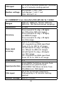
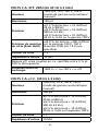
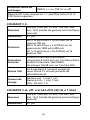
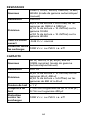
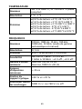
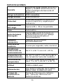
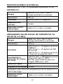
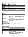
SPECIFICATIONS ............................................................ 22
SAFETY ..........................................................................23
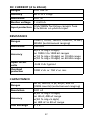
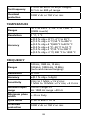
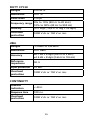
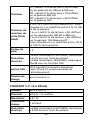
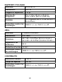
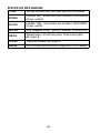
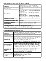
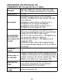
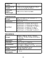
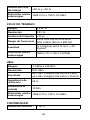
ELECTRICAL SPECIFICATIONS ....................................... 24

2
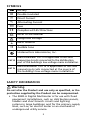
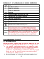
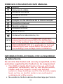
SYMBOLS
Battery
Double insulated
Direct Current
Alternating Current
Fuse
Complies with EU Directives
Refer to the Manual
Dangerous Voltage
Earth Ground
Audible tone
C
L
A
S
S
I
F
I
E
D
Underwriters Laboratories, Inc.
CAT III
MEASUREMENT CAT III is applicable to test and
measuring circuits connected to the distribution
part of the building’s low-voltage mains installation.
CAT IV
MEASUREMENT CAT IV is applicable to test and
measuring circuits connected at the source of
the building’s low-voltage mains installation.
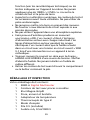
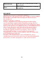
SAFETY INFORMATION
Warning
Do not alter the Product and use only as specified, or the
protection supplied by the Product can be compromised.
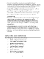
• The 38XR-A Digital Multimeter is for use with fixed
equipment installations, such as, distribution panels,
feeders and short branch circuits and lighting
systems in large buildings; and for the primary supply
level, such as, an electric meter or an overhead or
underground utility service.

3
• Do not exceed the maximum overload limits per
function (see specifications) nor the limits marked on the
instrument itself. Never apply more than 1000V dc/750 V
ac rms between the test lead and earth ground.
• Inspect the DMM, test leads and accessories before
every use. Do not use any damaged part.
• Never ground yourself when taking measurements. Do
not touch exposed circuit elements or test probe tips.
• Do not operate the instrument in an explosive
atmosphere.
• Exercise extreme caution when: measuring voltage
>20V // current >10mA // AC power line with
inductive loads // AC power line during electrical
storms // current, when the fuse blows in a circuit
with open circuit voltage >1000 V // servicing CRT
equipment.
• Always measure current in series with the load –
NEVER ACROSS a voltage source. Check fuse first.
Never replace a fuse with one of a different rating.
• Remove test leads before opening the Battery Cover
or case.
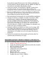
UNPACKING AND INSPECTION
Your shipping carton should include:
1 38XR-A Digital Multimeter
1 Test leads w/ alligator clips
1 Magne-Grip® Holster
1 Clip, magnet, and strap
1 Temperature Adapter
1 K-type thermocouple
1 Users Manual
1 9 V battery (installed)
1 mA fuse, 0.5A/1000 V

4
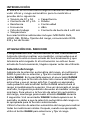
INTRODUCTION
The 38XR-A is a true rms autoranging handheld digital
multimeter for measuring or testing the following:
• DC and AC Voltage
• DC and AC Current
• Resistance
• Frequency
• Dutycycle
• Temperature
• Capacitance
• Diodes
• Continuity
• dBm
• 4 - 20 mA Loop Current
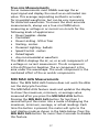
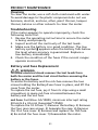
Additional features include: MIN MAX AVG, HOLD, REL,
PEAK±, Range Lock, RS-232 IR communication, and Backlight.
MAKING MEASUREMENTS
Verify Instrument Operation
Before attempting to make a measurement, verify that
the instrument is operational and the battery is good. If
the instrument is not operational, have it repaired before
attempting to make a measurement.
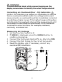
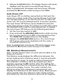
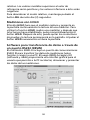
Range Selection
In addition to autoranging the 38XR-A allows you to
manually select and lock a range by pressing the RANGE
button. RANGE appears on the display to indicate that
manual ranging is active and the range is locked. When
appropriate, each subsequent press of the range button steps
the meter to the next higher range. When the highest range
is reached the next press returns the meter to the lowest
range. To return to autoranging press and hold the RANGE
button for 2 seconds. If RANGE still shows on the display,
autoranging is not appropriate for the selected function.
Use autorange for all initial measurements. Then, when
appropriate, use the RANGE button to select and lock a range.

5
WARNING
To avoid electrical shock while manual ranging use the
display annunciators to identify the actual range selected.
Correcting an Overload (0oor - 0o) Indication
An 0oor - 0o indication may appear on the display to indicate
that an overload condition exists. For voltage and current
measurements, an overload should be immediately corrected
by selecting a higher range. If the highest range setting does
not eliminate the overload, interrupt the measurement until
the problem is identified and eliminated. The 0o indication
is normal for some functions; for example, resistance,
continuity, and diode test.
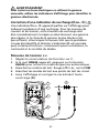
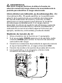
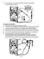
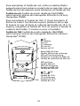
Measuring DC Voltage
1. Set the Function Switch to v.
2. If RANGE is displayed, press the RANGE button to
enable autoranging.
3. Connect the Test Leads: Red to E, Black to COM
4. Connect the Test Probes to the circuit test points.
5. Read the display, and, if necessary, correct any
overload (0o) conditions.
4
3
1
2
5
38XR-A

6
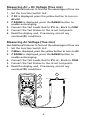
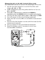
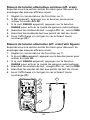
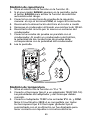
Measuring AC + DC Voltage (True rms)
See Additional Features to find out the advantages of true rms.
1. Set the Function Switch to v.
2. If DC is displayed, press the yellow button to turn on
AC+DC.
3. If RANGE is displayed, press the RANGE button to
enable autoranging.
4. Connect the Test Leads: Red to
E
, Black to COM
5. Connect the Test Probes to the circuit test points.
6. Read the display, and, if necessary, correct any
overload (0o) conditions.
Measuring AC Voltage (True rms)
See Additional Features to find out the advantages of true rms.
1. Set the Function Switch to V.
2. If dBm is displayed, press the yellow button to turn on AC.
3. If RANGE is displayed, press the RANGE button to
enable autoranging.
4. Connect the Test Leads: Red to E, Black to COM
5. Connect the Test Probes to the circuit test points.
6. Read the display, and, if necessary, correct any
overload (0o) conditions.
5
3
2
6
4
1
38XR-A

7
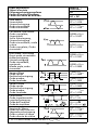
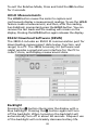
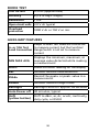
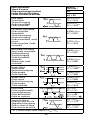
Input Waveform
Signal d’entrée
Eingangsschwingungsform
Forma d’onda d’ingresso
Forma de onda de entrada
38XR-A
Ture rms *
AC
AC + DC
Sine Wave
Sinusoïdale
Sinusschwingung
Onda sinusoidale
Onda sinusoidal
0.707 x V
peak
CF = 1.414
0.707 x V
peak
CF = 1.414
Full Wave, Sine Wave
Onde complète,
Sinusoïdale
Volle Schwingung,
Sinusschwingung
Onda sinusoidale, onda
intera
Onda completa, Onda
sinusoidal
0.308 x V
peak
CF = 3.247
0.707 x V
peak
CF = 1.414
Half-Wave, Sine Wave
Demi-onde, sinusoïdale
Halbschwingung,
Sinusschwingung
Onda sinusoidale,
semionda
Media onda, onda
sinusoidal
0.386 x V
peak
CF = 2.591
0.500 x V
peak
CF = 2.000
Square Wave
Onde carrée
Rechteckschwingung
Onda quadra
Onda cuadrada
1.000 x V
peak
CF = 1.000
1.000 x V
peak
CF = 1.000
Square Wave
Onde carrée
Rechteckschwingung
Onda quadra
Onda cuadrada
0.500 x V
peak
CF = 2.000
0.707 x V
peak
CF = 1.414
Pulse Wave
Onde impulsionnelle
Impulsschwingung
Onda dell’impulso
Onda de impulsos
V
peak
x K
CF = 1 / K
V
peak
x
CF =
V
peak
/
Sawtooth Wave
Onde en dent de scie
Sägezahnschwingung
Onda a denti di sega
Onda diente de sierra
0.577 x V
peak
CF = 1.733
0.577 x V
peak
CF = 1.733
* CF = Crest Factor, Crest Factor = V
peak
/ V
rms

8
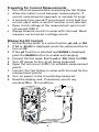
Preparing for Current Measurements
• Turn off circuit power before connecting the Test Probes.
• Allow the meter to cool between measurements, if
current measurements approach or exceeds 10 amps.
• A warning tone sounds if you connect a test lead to a
current input while a current function is not selected.
• Open circuit voltage at the measurement point must
not exceed 1000 V.
• Always measure current in series with the load. Never
measure current across a voltage source.
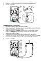
Measuring DC Current
1. Set the Function Switch to a current function, μA, mA, or 10A.
2. If
AC
or
AC+DC
is displayed, press the yellow button to
turn on
DC
.
3. If the
μA
function is selected and
RANGE
is displayed,
press the
RANGE
button to enable autoranging.
4. Connect the Test Leads: Red to
mA
or
10A
, Black to
COM
.
5. Turn off power to the circuit being measured.
6. Open the test circuit (X) to establish measurement
points.
7. Connect the Test Probes in series with the load (to the
measurement points).
8. Turn on power to the circuit being measured.
9. Read the display, and, if necessary, correct any
overload (0oor - 0o) conditions.
5
8
6
7
1
4
3
9
38XR-A
2

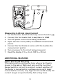
9
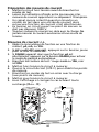
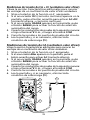
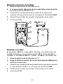
Measuring AC or AC+DC Current (True rms)
See Additional Features to find out the advantages of true rms.
1. Set the Function Switch to a current function and
range, μA, mA, or 10A.
2. If DC is displayed, press the yellow button to turn on
AC or AC+DC.
3. If the μA or mA function is selected and RANGE is
displayed, press the RANGE button to enable autoranging.
4. Connect the Test Leads: Red to mA or 10A, Black to COM
5. Turn off power to the circuit being measured.
6. Open the test circuit (X) to establish measurement
points.
7. Connect the Test Probes in series with the load (to the
measurement points).
8. Turn on power to the circuit being measured.
9. Read the display, and, if necessary, correct any
overload (0o) conditions.
5
8
6
7
1
4
2
3
9
38XR-A

10
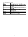
Input Waveform
Signal d’entrée
Eingangsschwingungsform
Forma d’onda d’ingresso
Forma de onda de entrada
38XR-A
Ture rms *
AC
AC + DC
Sine Wave
Sinusoïdale
Sinusschwingung
Onda sinusoidale
Onda sinusoidal
0.707 x V
peak
CF = 1.414
0.707 x V
peak
CF = 1.414
Full Wave, Sine Wave
Onde complète,
Sinusoïdale
Volle Schwingung,
Sinusschwingung
Onda sinusoidale, onda
intera
Onda completa, Onda
sinusoidal
0.308 x V
peak
CF = 3.247
0.707 x V
peak
CF = 1.414
Half-Wave, Sine Wave
Demi-onde, sinusoïdale
Halbschwingung,
Sinusschwingung
Onda sinusoidale,
semionda
Media onda, onda
sinusoidal
0.386 x V
peak
CF = 2.591
0.500 x V
peak
CF = 2.000
Square Wave
Onde carrée
Rechteckschwingung
Onda quadra
Onda cuadrada
1.000 x V
peak
CF = 1.000
1.000 x V
peak
CF = 1.000
Square Wave
Onde carrée
Rechteckschwingung
Onda quadra
Onda cuadrada
0.500 x V
peak
CF = 2.000
0.707 x V
peak
CF = 1.414
Pulse Wave
Onde impulsionnelle
Impulsschwingung
Onda dell’impulso
Onda de impulsos
V
peak
x K
CF = 1 / K
V
peak
x
CF =
V
peak
/
Sawtooth Wave
Onde en dent de scie
Sägezahnschwingung
Onda a denti di sega
Onda diente de sierra
0.577 x V
peak
CF = 1.733
0.577 x V
peak
CF = 1.733
* CF = Crest Factor, Crest Factor = V
peak
/ V
rms

11
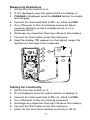
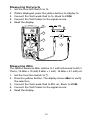
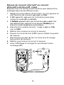
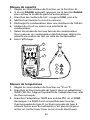
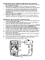
Measuring Resistance
1. Set the Function Switch to Ω.
2. If is displayed, press the yellow button to display Ω.
3. If RANGE is displayed, press the RANGE button to enable
autoranging.
4. Connect the Test Leads: Red to E, Black to COM
5. Turn off power to the circuit being measured. Never
measure resistance across a voltage source or on a
powered circuit.
6. Discharge any capacitors that may influence the reading.
7. Connect the Test Probes across the resistance.
8. Read the display. If 0o appears on the highest range, the
resistance is too large to be measured.
5
7
6
4
1
2
3
8
38XR-A
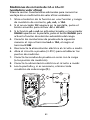
Testing for Continuity
1. Set the Function Switch to .
2. If Ω is displayed, press the yellow button to display .
3. Connect the Test Leads: Red to E, Black to COM
4. Turn off power to the circuit being measured.
5. Discharge any capacitors that may influence the reading.
6. Connect the Test Probes across the resistance.
7. Listen for the tone that indicates continuity (< 40 Ω).

12
6
4
5
7
3
1
2
38XR-A
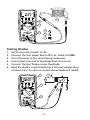
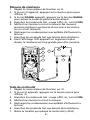
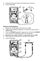
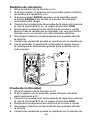
Testing Diodes
1. Set the Function Switch to
d
.
2. Connect the Test Leads: Red to E, Black to COM
3. Turn off power to the circuit being measured.
4. Free at least one end of the diode from the circuit.
5. Connect the Test Probes across the diode.
6. Read the display. A good diode has a forward voltage drop
of about 0.6 V. An open or reverse biased diode will read 0o.
2
1
3
5
4
6
38XR-A

13
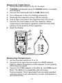
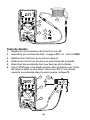
Measuring Capacitance
1. Set the Function Switch to the P function.
2. If RANGE is displayed, press the RANGE button to enable
autoranging.
3. Connect the Test Leads: Red to COM, Black to h
4. Turn off power to the circuit being measured.
5. Discharge the capacitor using a 100 kΩ resistor.
6. Free at least one end of the capacitor from the circuit.
7. Connect the Test Probes across the capacitor. When
measuring an electrolytic capacitor match the test lead
polarity to the polarity of the capacitor.
8. Read the display.
1
5
6
7
3
4
8
2
38XR-A
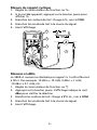
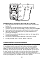
Measuring Temperature
1. Set the function Switch to °C or °F.
2. Connect the K-type thermocouple to a TEMP adapter
(XR-TA). Match the polarity of the adapter to the polarity
of the thermocouple.
3. Connect the TEMP adapter to the E and COM inputs.
Note: The 38XR-A is compatible with all K-type
thermocouples. The K-type bead thermocouple supplied
with the meter is not intended for contact with liquids or
electrical circuits.

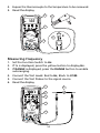
14
4. Expose the thermocouple to the temperature to be measured.
5. Read the display.
2
4
K
3
1
5
38XR-A
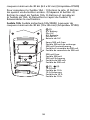
Measuring Frequency
1. Set the Function Switch to Hz.
2. If % is displayed, press the yellow button to display Hz.
3. If RANGE is displayed, press the RANGE button to enable
autoranging.
4. Connect the Test Leads: Red to Hz, Black to COM.
5. Connect the Test Probes to the signal source.
6. Read the display.
1
5
4
2
6
3
38XR-A
La page est en cours de chargement...
La page est en cours de chargement...
La page est en cours de chargement...
La page est en cours de chargement...
La page est en cours de chargement...
La page est en cours de chargement...
La page est en cours de chargement...
La page est en cours de chargement...
La page est en cours de chargement...
La page est en cours de chargement...
La page est en cours de chargement...
La page est en cours de chargement...
La page est en cours de chargement...
La page est en cours de chargement...
La page est en cours de chargement...
La page est en cours de chargement...
La page est en cours de chargement...
La page est en cours de chargement...
La page est en cours de chargement...
La page est en cours de chargement...
La page est en cours de chargement...
La page est en cours de chargement...
La page est en cours de chargement...
La page est en cours de chargement...
La page est en cours de chargement...
La page est en cours de chargement...
La page est en cours de chargement...
La page est en cours de chargement...
La page est en cours de chargement...
La page est en cours de chargement...
La page est en cours de chargement...
La page est en cours de chargement...
La page est en cours de chargement...
La page est en cours de chargement...
La page est en cours de chargement...
La page est en cours de chargement...
La page est en cours de chargement...
La page est en cours de chargement...
La page est en cours de chargement...
La page est en cours de chargement...
La page est en cours de chargement...
La page est en cours de chargement...
La page est en cours de chargement...
La page est en cours de chargement...
La page est en cours de chargement...
La page est en cours de chargement...
La page est en cours de chargement...
La page est en cours de chargement...
La page est en cours de chargement...
La page est en cours de chargement...
La page est en cours de chargement...
La page est en cours de chargement...
La page est en cours de chargement...
La page est en cours de chargement...
La page est en cours de chargement...
La page est en cours de chargement...
La page est en cours de chargement...
La page est en cours de chargement...
La page est en cours de chargement...
La page est en cours de chargement...
La page est en cours de chargement...
La page est en cours de chargement...
La page est en cours de chargement...
La page est en cours de chargement...
La page est en cours de chargement...
La page est en cours de chargement...
La page est en cours de chargement...
La page est en cours de chargement...
La page est en cours de chargement...
La page est en cours de chargement...
La page est en cours de chargement...
La page est en cours de chargement...
La page est en cours de chargement...
La page est en cours de chargement...
La page est en cours de chargement...
La page est en cours de chargement...
La page est en cours de chargement...
La page est en cours de chargement...
La page est en cours de chargement...
La page est en cours de chargement...
La page est en cours de chargement...
La page est en cours de chargement...
La page est en cours de chargement...
La page est en cours de chargement...
La page est en cours de chargement...
La page est en cours de chargement...
La page est en cours de chargement...
La page est en cours de chargement...
La page est en cours de chargement...
La page est en cours de chargement...
La page est en cours de chargement...
La page est en cours de chargement...
-
 1
1
-
 2
2
-
 3
3
-
 4
4
-
 5
5
-
 6
6
-
 7
7
-
 8
8
-
 9
9
-
 10
10
-
 11
11
-
 12
12
-
 13
13
-
 14
14
-
 15
15
-
 16
16
-
 17
17
-
 18
18
-
 19
19
-
 20
20
-
 21
21
-
 22
22
-
 23
23
-
 24
24
-
 25
25
-
 26
26
-
 27
27
-
 28
28
-
 29
29
-
 30
30
-
 31
31
-
 32
32
-
 33
33
-
 34
34
-
 35
35
-
 36
36
-
 37
37
-
 38
38
-
 39
39
-
 40
40
-
 41
41
-
 42
42
-
 43
43
-
 44
44
-
 45
45
-
 46
46
-
 47
47
-
 48
48
-
 49
49
-
 50
50
-
 51
51
-
 52
52
-
 53
53
-
 54
54
-
 55
55
-
 56
56
-
 57
57
-
 58
58
-
 59
59
-
 60
60
-
 61
61
-
 62
62
-
 63
63
-
 64
64
-
 65
65
-
 66
66
-
 67
67
-
 68
68
-
 69
69
-
 70
70
-
 71
71
-
 72
72
-
 73
73
-
 74
74
-
 75
75
-
 76
76
-
 77
77
-
 78
78
-
 79
79
-
 80
80
-
 81
81
-
 82
82
-
 83
83
-
 84
84
-
 85
85
-
 86
86
-
 87
87
-
 88
88
-
 89
89
-
 90
90
-
 91
91
-
 92
92
-
 93
93
-
 94
94
-
 95
95
-
 96
96
-
 97
97
-
 98
98
-
 99
99
-
 100
100
-
 101
101
-
 102
102
-
 103
103
-
 104
104
-
 105
105
-
 106
106
-
 107
107
-
 108
108
-
 109
109
-
 110
110
-
 111
111
-
 112
112


dans d''autres langues
- English: Amprobe 38XR-A User manual
- español: Amprobe 38XR-A Manual de usuario
Documents connexes
-
Amprobe HD110C Digital Multimeter Manuel utilisateur
-
-
-
-
-
-
Amprobe Digital Multimeter AM-420 Manuel utilisateur
-
-
-
Autres documents
-
Facom 714A Le manuel du propriétaire
-
Velleman DVM9912 Manuel utilisateur
-
PROPOINT 8344665 Le manuel du propriétaire
-
BEHA AMPROBE Beha-Amprobe AM-520-EUR Digital Multimeter Manuel utilisateur
-
KPS DMM3000 Le manuel du propriétaire
-
koban KPA-1000 Mode d'emploi
-
-
Fluke Kit d´accessoires pour cordons de mesure 2000ACC Mode d'emploi
-
-
Wavetek TMD90 Manuel utilisateur