PROPOINT 8344665 Le manuel du propriétaire
- Catégorie
- Multimètres
- Taper
- Le manuel du propriétaire

8344665
Please read this manual before use.
V 3.01
User Manual
5-in-1 Autoranging
Digital Multimeter

2For technical questions call 1-800-665-8685
8344665V 3.01
5-in-1 Autoranging
Digital Multimeter
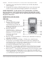
INTRODUCTION
This versatile multimeter can be used for taking a variety of
measurements, including AC and DC voltage, AC and DC current,
resistance and continuity.
The built-in sensors allow for accurate reading of sound, luminance,
and humidity. This meter was designed for the homeowner,
hobbyist, and professional needing to make electrical and electronic
equipment measurements.
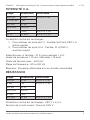
SPECIFICATIONS
Display 3-3/4 digit LCD with a backlight
Measurement Rate Updates 2 to 3 / sec.
Over-Range
Indication
“OL” shown on the display
Negative Polarity
Indication
"–" displayed automatically
Low Battery
Indication
+– is displayed when the battery voltage
drops below the operating voltage
Full Range Overload Protection

5-in-1 Autoranging Digital Multimeter
3
Visit www.princessauto.com for more information
8344665 V 3.01
Auto Power Off About 15 minutes after the power is
turned on.
To resume, the power needs to be turned
off then turned on again.
Operating
Temperature
0°C to 40°C, < 75%RH
Storage
Temperature
-30°C to 60°C, < 85%RH
Operating Altitude 0 m to 2000 m
Power Single Standard 9V battery
Size 162 mm x 83 mm x 47 mm
Weight 310 g (including battery)
Accessories Test Leads, 9V Battery, Owner’s Manual
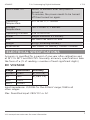
ELECTRICAL SPECIFICATIONS
Accuracy is specified for a period of one year after calibration and
at 18°C to 28°C and RH<75%. Normally, accuracy specifications take
the form of: ± (% of reading + number of least significant digits)
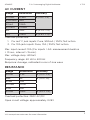
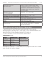
DC VOLTAGE
Range Resolution Accuracy
400mV 0.1mV ± (1.0% +5)
4V 1mV ± (0.8% +3)
40V 10mV
250V 100mV
Input impedance: >1,000Ω for the 400mV range; 10Ωfor all
other ranges
Max. Permitted input: 250V DC or AC

5-in-1 Autoranging Digital Multimeter
4For technical questions call 1-800-665-8685
8344665
V 3.01
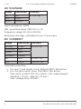
AC VOLTAGE
Range Resolution Accuracy
4V 1mV ± (1.0% +5)
40V 10mV
250V 100mV
Input impedance: 10MΩ
Max. permitted input: 250V DC or AC
Frequency range: 40 Hz to 400 Hz
Response: Average, calibrated in rms of sine wave
DC CURRENT
Range Resolution Accuracy
400ΩA 0.1ΩA± (1.2% +3)
4,000ΩA 1ΩA
40mA 10Ω!
400mA 100ΩA
4A 1mA ± (1.8% +3)
10A 10mA ± (2.0% +5)
Overload protection:
1. For mA°C jack inputs: Fuse, 500mA/250V, fast action
2. For 10A jack inputs: Fuse, 10A/250V, fast action
Max. input current: 10A (For inputs > 5A: measurement
duration < 10 sec., interval > 15 min.)
Max. voltage drop: 400mV

5-in-1 Autoranging Digital Multimeter
5
Visit www.princessauto.com for more information
8344665 V 3.01
AC CURRENT
Range Resolution Accuracy
400ΩA 0.1ΩA± (1.5% + 5)
4,000ΩA 1ΩA
40mA 10ΩA
400mA 100ΩA
4A 1mA ± (2.0% + 5)
10A 10mA ± (2.5% + 5)
Overload protection:
1. For mA°C jack inputs: Fuse, 500mA / 250V, fast action
2. For 10A jack inputs: Fuse, 10A / 250V, fast action
Max. input current: 10A (For inputs > 5A: measurement duration
< 10 sec., interval > 15 min.)
Max. voltage drop: 400mV
Frequency range: 40 Hz to 400 Hz
Response: Average, calibrated in rms of sine wave
RESISTANCE
Range Resolution Accuracy
400Ω0.1Ω± (1.0% + 5)
4kΩ1Ω± (1.0% +3)
40kΩ10Ω
400kΩ100Ω
4MΩ1kΩ
40MΩ10kΩ± (2.0% +5)
Overload protection: 250V AC/DC
Open circuit voltage: approximately 0.25V

5-in-1 Autoranging Digital Multimeter
6For technical questions call 1-800-665-8685
8344665
V 3.01
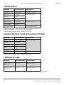
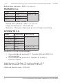
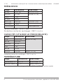
FREQUENCY
Range Resolution Accuracy
10 Hz 0.01 Hz ± (1.0% + 3)
100 Hz 0.1 Hz ± (0.8% +3)
1 kHz 1 Hz
10 kHz 10 Hz
100 kHz 100 Hz ± (1.0% + 3)
200 kHz 1 kHz
> 200 kHz Not Specified
Input voltage: 1 V rms to 20 V rms
Overload protection: 250V AC/DC
CAPACITANCE (USE RELATIVE MODE)
Range Resolution Accuracy
4nF 0.001nF ± (4.0% +5)
40nF 0.01nF
400nF 0.1nF
4ΩF1nF
40ΩF10nF
100ΩF100nF ± (8.0% + 5)
Overload protection: 250V AC/DC
TEMPERATURE
Range Resolution Accuracy
-20°C to
400°C
0.1°C ±1.5% ±3°C
400°C to
1,000°C
1°C ±2.0% ±3°C
Overload protection: Fuse, 500mA / 250V, fast action

5-in-1 Autoranging Digital Multimeter
7
Visit www.princessauto.com for more information
8344665 V 3.01
Notes:
1. Use K-type thermocouple wire.
2. Accuracy does not include thermocouple error.
3. Accuracy specification assumes ambient temperature is stable
to ± 1°C. For ambient temperature changes of ± 5°C, rated
accuracy applies after 1 hour.
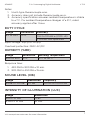
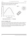
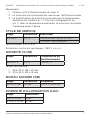
DUTY CYCLE
Range Resolution Accuracy
5% to 95% 0.1% 1 Hz to 10 kHz: ± (2.0% +5)
> 10 kHz: Not Specified
Input voltage: 3Vp-p to 10Vp-p
Overload protection: 250V AC/DC
HUMIDITY (%RH)
Range Resolution Working Temperature
30% to 90% 0.1% 0°C to 40°C
Response time:
1. 45% RH to 90% RH ≤ 10 min.
2. 90% RH to 45% RH ≤ 15 min.
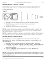
SOUND LEVEL (DB)
Range Resolution Frequency
35 dB to 100 dB 0.1 dB 100 Hz to 10,000 Hz
INTENSITY OF ILLUMINATION (LUX)
Range Resolution
400 x 10 Lux 1 Lux
4,000 x 10 Lux 10 Lux

5-in-1 Autoranging Digital Multimeter
8For technical questions call 1-800-665-8685
8344665
V 3.01
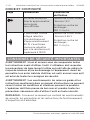
DIODE AND CONTINUITY
Range Introduction Test Condition
The approximate forward
voltage drop of the diode
will be displayed.
Open circuit voltage:
approximately 1.5V
The built-in buzzer will
sound if the resistance is
approximately 50Ω. The
buzzer will not sound if the
resistance is more than 120Ω.
Open circuit voltage:
approximately 0.45V
Overload protection:
250V AC/DC
Overload protection:
250V AC/DC
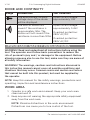
IMPORTANT SAFETY PRECAUTIONS
WARNING! Read and understand all instructions before using the
tool. The operator must follow basic precautions to reduce the
risk of personal injury and / or damage to the equipment. Before
allowing someone else to use the tool, make sure they are aware of
all safety information.
WARNING! The warnings, cautions and instructions discussed in
this instruction manual cannot cover all possible conditions and
situations that may occur. Common sense and caution are factors
that cannot be built into this product, but must be supplied by
the operator.
NOTE: Keep this manual for the safety warnings, precautions and
operating, inspection and maintenance instructions.
WORK AREA
1. Operate in a safe work environment. Keep your work area
clean and well lit.
2. Keep anyone not wearing the appropriate safety equipment
away from the work area.
NOTE: Minimize distractions in the work environment.
Distractions can cause you to lose control of the tool.

5-in-1 Autoranging Digital Multimeter
9
Visit www.princessauto.com for more information
8344665 V 3.01
3. Do not operate power tools in explosive atmospheres, such
as in the presence of flammable liquids, gases, or dust. Power
tools create sparks, which may ignite the dust or fumes.
4. Always lock up tools and keep them out of the reach
of children.
PERSONAL SAFETY
CAUTION! Wear protective equipment approved by the Canadian
Standards Association (CSA) or American National Standards
Institute (ANSI) when using the digital multimeter.
1. Dress properly, wear protective equipment. Use breathing, ear,
eye, face, foot, hand, and head protection. Always wear ANSI
approved impact safety goggles, which must provide both
frontal and side protection. Protect your hands with suitable
gloves. Wear a full face shield if your work creates metal
filings or wood chips. Protect your head from falling objects
by wearing a hard hat. Wear an ANSI approved dust mask or
respirator when working around metal, wood and chemical
dusts and mists. Wear ANSI approved earplugs. Protective,
electrically non-conductive clothes and non-skid footwear
are recommended when working. Wear steel-toed boots to
prevent injury from falling objects.
2. Control the tool, personal movement and the work
environment to avoid personal injury or damage to the tool.
Stay alert, watch what you are doing and use your
common sense.
3. Do not operate any machine / tool when tired or under the
influence of drugs, alcohol or medications.
4. Do not overreach when operating a tool. Proper footing and
balance enables better control of a tool in
unexpected situations.

5-in-1 Autoranging Digital Multimeter
10 For technical questions call 1-800-665-8685
8344665
V 3.01
SPECIFIC SAFETY PRECAUTIONS
This multimeter has been designed according to IEC-61010
concerning electronic measuring instruments with a measurement
category II (CAT II 250V) and pollution degree 2. Measuring
Category II (CAT II) is for measurement performed on circuits
directly connected to low voltage installation (for example,
measurements on household appliances, portable tools and similar
equipment). Do not use this multimeter for measurements within
Measurements Category II and IV.
WARNING! To avoid possible electric shock or personal injury,
follow these guidelines:
1. Ensure that the battery is correctly placed in the battery case
and connected properly.
2. Do not operate with the battery cover or portions of the case
removed or loosened.
3. Do not use the multimeter if it is damaged. Before you use
the multimeter, inspect the case. Inspect the test leads
for damaged insulation or exposed metal. Check test lead
continuity. Damaged leads should be replaced.
4. Do not use the multimeter if it operates abnormally. Protection
may be impaired. When in doubt, have the multimeter serviced
by an authorized service centre.
5. Do not operate the multimeter around explosive gas, vapour
or dust.
6. Do not apply a voltage or current higher than the selected
range’s upper limit between terminals.
7. Before use, verify the multimeter’s operation by measuring a
known voltage.
8. When measuring current, turn off the power to the circuit
before connecting the multimeter to the circuit. Remember to
place the multimeter in series with the circuit.
9. Use caution when working above 30V AC rms, 42V peak, or
60V DC. Such voltages pose a shock hazard.
10. Do not touch any naked conductor with bare hands or skin and
do not ground yourself.

5-in-1 Autoranging Digital Multimeter
11
Visit www.princessauto.com for more information
8344665 V 3.01
11. Connect the black test lead before connecting the red test
lead. When disconnecting the test leads, always disconnect the
red test lead first.
12. Remove the test leads from the multimeter before opening the
battery cover or the case.
13. Replace the battery as soon as the low battery indicator
appears on the LCD display.
14. When in Relative mode or Data Hold mode, REL or is
displayed on the LCD display. Caution must be used because
hazardous voltage may be present.
CAUTION! To avoid possible damage to the multimeter or to the
equipment under test, follow these guidelines:
1. Disconnect the circuit power and discharge all capacitors
before measuring resistance or continuity.
2. Select the proper function and range for your measurement.
3. Before measuring current, turn off the power to the circuit
before connecting the multimeter to the circuit.
4. Before rotating the range switch to change functions,
disconnect the test leads from the circuit under test.
5. Remove the test leads from the multimeter before opening the
battery cover or the case.
6. When finished measuring, switch off the power. Be sure to
remove the battery when storing for long periods to avoid
leakage problems.
7. Do not use or store this instrument in direct sunlight, high
temperature and high humidity.
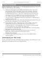
TOOL USE AND CARE
WARNING! Do not use the tool if the power switch does not
function properly. Any tool that cannot be controlled with the ON /
OFF switch is dangerous and must be repaired.
1. Use the correct tool for the job. Maximise performance and
safety by using the tool for its intended task.
2. Do not modify this tool or use for a purpose for which it was
not designed.

5-in-1 Autoranging Digital Multimeter
12 For technical questions call 1-800-665-8685
8344665
V 3.01
3. This tool was designed for a specific function.
Do Not:
a. Modify or alter the tool, all parts and accessories are
designed with built-in safety features that may be
compromised if altered.
b. Use the tool in a way for which it was not designed.
UNPACKING
1. Carefully remove the tool from the package.
a. Retain the packing material until you have carefully
inspected and satisfactorily operated the tool.
2. Make sure that all the items in the parts list are included.
3. Inspect the parts carefully to make sure the tool was not
damaged while shipping.
WARNING! If any part is missing, do not operate the tool until the
missing parts are replaced. Failure to do so could result in serious
personal injury.
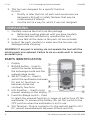
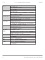
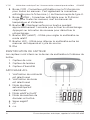
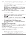
PARTS IDENTIFICATION
1 Display
2 RANGE button – Used to
switch the meter between
the autorange mode and the
manual range mode.
3. SELECT button – Used to
switch the multimeter between
DC and AC functions, or
between diode and
continuity functions.
4. HOLD button – Used to hold
present reading on the display.
5. Function-Range switch – Used
to select the required function or range, as well as turn off the
multimeter. To preserve the battery life, set this switch to the
OFF position when the multimeter is not in use.
6. 10A Terminal – Plug-in connector for the red test lead for AC/
DC current measurements between 400mA and 10A.

5-in-1 Autoranging Digital Multimeter
13
Visit www.princessauto.com for more information
8344665 V 3.01
7. mA°C Terminal – Plug-in connector for the red test lead for
AC/DC current measurements less than 400 mA.
It is also the plug-in connector for the red plug (+) of the
K-type thermocouple.
8. COM Terminal – Plug-in connector for the black test lead for
all measurements. It is also the plug-in connector for the black
plug (-) of the K-type thermocouple.
9. VΩHz Terminal – Plug-in connector for the red test
lead for all measurements except temperature and current
measurements.
10. Button – Press and hold down this button for approximately
1 second to turn on the backlight. Press the button again to
turn off the backlight.
11. REL Button – Used to set the multimeter to Relative mode.
12. Hz% Button – Used to switch the multimeter between
frequency and duty cycle measurements.
13. Holster
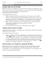
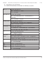
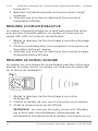
SENSOR IDENTIFICATION
The sensors are located at the
top of the multimeter inside
the case.
1. Sound Sensor
2. Light Sensor
3. Humidity Sensor
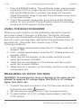
LCD DISPLAY
1. Continuity test is selected
2. Diode test is selected
3. Autorange mode is
selected
4. Relative mode is active
5. Data HOLD is enabled
6. Negative sign
7. DC
8. AC
9. Low battery indicator
10. Units of measurement (see the following table)

5-in-1 Autoranging Digital Multimeter
14 For technical questions call 1-800-665-8685
8344665
V 3.01
mV, V Voltage Unit
mV: Millivolt; V:Volt
1V = 103mV
ΩA, mA, A Current Unit
ΩA: Microamp; mA: Milliamp; A: Ampere
1A = 103mA = 106ΩA
Ω, kΩ, MΩResistance Unit
Ω: Ohm; kΩ: Kilohm; MΩ: Megohm
1MΩ = 103kΩ - 106Ω
F, nF, ΩFCapacitance Unit
F: Farad; nF: Nanofarad; ΩF: Microfarad
1F = 106ΩF = 109nF = 1012pF
°C Temperature Unit
°C: Degrees Celsius
Hz, kHz,
MHz
Frequency Unit
Hz: Hertz; kHz: Kilohertz; MHz: Megahertz
1MHz = 103kHz = 106Hz
% Used For Duty Cycle Measurement
%: Percent
lux Unit Of Illumination
dB Unit Of Sound Measurement
%RH Unit Of Relative Humidity
%: Percent

5-in-1 Autoranging Digital Multimeter
15
Visit www.princessauto.com for more information
8344665 V 3.01
OPERATION
USING RELATIVE MODE
Relative mode is available for all functions except for frequency and
duty cycle functions. When Relative mode is enabled, the multimeter
stores the present reading as a reference for
subsequent measurements
To enable Relative mode:
1. Take a reading with the multimeter, and then press the REL
button. The multimeter enables Relative mode and stores the
present reading as a reference for subsequent measurements.
REL appears on the LCD display along with a zero reading.
2. Take a new measurement. The display shows the difference
between the reference measurement and the
new measurement.
3. To exit Relative mode, press the REL button again.
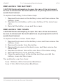
USING DATA HOLD MODE
When Data Hold mode is enabled, the multimeter holds the present
reading on the display.
To enable Data Hold mode:
1. Take a reading with the multimeter, and then press the HOLD
button. appears on the LCD display indicating that Data Hold
mode has been enabled. The multimeter will hold the reading
on the display until the multimeter exits the Data Hold mode.
2. To exit Data Hold mode, press the HOLD button again. The
indicator no longer appears on the display.
SWITCHING TO MANUAL RANGE MODE
Autorange mode is enabled by default in measurement functions
that have both autorange and manual range modes. When the
multimeter is in autorange mode, AUTO appears on the display. To
switch to manual range mode:

5-in-1 Autoranging Digital Multimeter
16 For technical questions call 1-800-665-8685
8344665
V 3.01
1. Press the RANGE button. The multimeter enters manual range
mode and AUTO no longer appears on the display. Each time
that the RANGE button is pressed, the range will increase.
When the highest range is reached, the multimeter wraps back
to the lowest range.
2. To exit the manual range mode, press and hold the RANGE
button for two seconds. The multimeter returns to autorange
mode and AUTO appears on the display.
USING THE BUILT-IN BUZZER
When you press a button on the multimeter, the built-in buzzer
will sound a beep if the press is effective. The buzzer will beep
five times, one minute before the meter turns off automatically,
and will sound one long beep right before the multimeter turns off
automatically. The buzzer also sounds in any of the
following conditions:
1. In AC voltage measurement when the AC voltage under test
exceeds 750V.
2. In DC voltage measurement when the DC voltage under test
exceeds 1,000V.
3. When the unit ΩA appears on the display and the current
under test exceeds 4,000ΩA.
4. When the unit mA appears on the display and the current
under test exceeds 400mA.
5. When the unit A appears on the display and the current under
test exceeds 10A.
MEASURING AC OR DC VOLTAGE
WARNING! To avoid electric shock or damage to the meter, do not
attempt to measure DC voltage higher than 250V or AC voltage
higher than 250V rms.
1. Connect the black test lead to the COM terminal and the red
test lead to the VΩHz terminal.
2. Set the function-range switch to the V≂ range position.
3. To select either AC or DC voltage measurement, press the
FUNC button.

5-in-1 Autoranging Digital Multimeter
17
Visit www.princessauto.com for more information
8344665 V 3.01
NOTE: If you are using the manual range mode, and the
voltage to be tested is unknown beforehand, set the
function-range switch to the highest range position first and
then reduce range by range until the satisfactory resolution
is obtained.
4. Connect the red test lead to the positive terminal of the circuit
to be tested and the black test lead to the negative terminal of
the circuit.
5. Read the DC voltage value on scale B.
MEASURING AC OR DC CURRENT
NOTE: ≂ denotes both direct and alternating current.
1. Connect the black test lead to the COM terminal. If the current
to be measured is less than 400mA, connect the red test lead
to the mA°C terminal. If the current to be measured is between
400mA and 10A, connect the red test lead to the 10A terminal.
NOTE: When using the 10A terminal, the function-range switch
must always be in the 10A≂ range position.
2. Set the function-range switch to the ΩA≂, mA≂, or
10A≂ range position.
NOTE: If you are using either the autorange or manual range
mode, and the voltage to be tested is unknown beforehand,
set the function-range switch to the highest range position
first and then reduce range by range until the satisfactory
resolution is obtained.
3. To select either AC or DC current measurement, press the
FUNC button.
4. Remove power from the circuit to be tested and discharge
any capacitors and inductors.
5. Connect the test leads into the circuit so that the meter is in
series with the circuit where current is to be measured. The
current should enter through the red lead (positive side) and
leave through the black lead (negative side) in order for the
multimeter to indicate in an upscale direction.

5-in-1 Autoranging Digital Multimeter
18 For technical questions call 1-800-665-8685
8344665
V 3.01
6. Turn on the power to the circuit under test, and then read
the current on the display. For DC current measurement, the
polarity of the red test lead connection will also be indicated.
7. Turn off the power to the circuit under test. Discharge all
capacitors and inductors. Remove the test leads from the
circuit under test.
MEASURING RESISTANCE
1. Connect the black test lead to the COM terminal and the red
test lead to the VΩHz terminal.
NOTE: The polarity of the red lead is positive (+).
2. Set the function-range switch to the Ω range position.
3. Make sure the load to be tested is without power and all
capacitors are fully discharged.
4. Connect the test leads across the resistance under
measurement, and then read the resistance on the display. For
resistance about 1MΩ, the multimeter may take a few seconds
to stabilize the reading. This is normal for high
resistance measuring.
NOTE: When the input is connected (i.e. at open circuit), OL
will be displayed for the over range condition.
CONTINUITY TEST
1. Connect the black test lead to the COM terminal and the red
test lead to the VΩHz terminal.
2. Set the function-range switch to the range position.
3. Press the FUNC button until appears on the display.
4. Turn off the power to the circuit under test, and then discharge
all capacitors and inductors.
5. Connect the test leads across the circuit being measured.
6. If the resistance of the circuit is less than 50Ω, the built-in
buzzer will sound.

5-in-1 Autoranging Digital Multimeter
19
Visit www.princessauto.com for more information
8344665 V 3.01
MEASURING CAPACITANCE
1. Connect the black test lead to the COM terminal and the red
test lead to the VΩHz terminal.
2. Set the function-range switch to the range position.
3. Discharge the capacitor being measured.
4. Connect the test leads to the capacitor.
5. Wait until the reading is stable, and then read the capacitance
on the display.
NOTE: for high-capacitance measurement, it may take up
to 30 seconds for the multimeter to measure capacitance.
To improve the accuracy of low-capacitance measurements,
subtract the residual capacitance of the meter and the
test leads.
MEASURING FREQUENCY AND DUTY CYCLE
1. Connect the black test lead to the COM terminal and the red
test lead to the VΩHz terminal.
2. Set the function-range switch to the Hz% range position.
3. Press the Hz% button to select frequency or duty.
4. Connect the test leads across the source or load being
measured, and then read the value on the display.
NOTE: For frequency measurements, the voltage of the input
signal should be between 1V rms and 20V rms. For duty cycle
measurements, the voltage of the input signal should be
between 3Vp-p rms and 10Vp-p rms.
PERFORMING A DIODE TEST
1. Connect the black test lead to the COM terminal and the red
test lead to the VΩHz terminal.
NOTE: The polarity of the red lead is positive (+).
2. Set the function-range switch to the range position.
3. Press the FUNC button until appears on the display.
4. Connect the red test lead to the anode of the diode being
tested, and the black test lead to the cathode.

5-in-1 Autoranging Digital Multimeter
20 For technical questions call 1-800-665-8685
8344665
V 3.01
5. The display shows the approximate forward voltage drop of
the diode. If the connection is reversed, OL will appear on
the display.
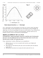
MEASURING TEMPERATURE
CAUTION! To avoid possible damage to the multimeter or other
equipment, remember that while the multimeter is rated for -20°C
to 1,000°C, the K-type thermocouple provided with the multimeter
is only rated to 250°C. For temperatures higher than 250°C, use a
higher rated thermocouple.
1. Set the function-range switch to the °C range position.
2. Connect the negative (black) plug of the K-type thermocouple
to the COM terminal and the positive (red) plug to the
mA°C terminal.
3. Connect the opposite end of the thermocouple to the object
being measured.
4. Wait until the reading is stable, and then read the temperature
on the display.
MEASURING RELATIVE HUMIDITY
This multimeter’s built-in humidity sensor can be used to measure
relative humidity. The sensor is located near the mark %RH on the
top of the multimeter.
1. Set the function-range switch to the %RH range position.
2. Place the multimeter in the environment where the relative
humidity measurement is required.
3. Wait until the reading is stable, and then read the relative
humidity value on the display.
La page charge ...
La page charge ...
La page charge ...
La page charge ...
La page charge ...
La page charge ...
La page charge ...
La page charge ...
La page charge ...
La page charge ...
La page charge ...
La page charge ...
La page charge ...
La page charge ...
La page charge ...
La page charge ...
La page charge ...
La page charge ...
La page charge ...
La page charge ...
La page charge ...
La page charge ...
La page charge ...
La page charge ...
La page charge ...
La page charge ...
La page charge ...
La page charge ...
La page charge ...
La page charge ...
-
 1
1
-
 2
2
-
 3
3
-
 4
4
-
 5
5
-
 6
6
-
 7
7
-
 8
8
-
 9
9
-
 10
10
-
 11
11
-
 12
12
-
 13
13
-
 14
14
-
 15
15
-
 16
16
-
 17
17
-
 18
18
-
 19
19
-
 20
20
-
 21
21
-
 22
22
-
 23
23
-
 24
24
-
 25
25
-
 26
26
-
 27
27
-
 28
28
-
 29
29
-
 30
30
-
 31
31
-
 32
32
-
 33
33
-
 34
34
-
 35
35
-
 36
36
-
 37
37
-
 38
38
-
 39
39
-
 40
40
-
 41
41
-
 42
42
-
 43
43
-
 44
44
-
 45
45
-
 46
46
-
 47
47
-
 48
48
-
 49
49
-
 50
50


PROPOINT 8344665 Le manuel du propriétaire
- Catégorie
- Multimètres
- Taper
- Le manuel du propriétaire
dans d''autres langues
- English: PROPOINT 8344665 Owner's manual
Documents connexes
Autres documents
-
Velleman DVM9912 Manuel utilisateur
-
Amprobe HD160C Digital Multimeter Manuel utilisateur
-
 Wavetek Meterman 235 Le manuel du propriétaire
-
Wavetek 2015 Manuel utilisateur
-
-
Bosch Appliances 540H Manuel utilisateur
-
-
-
-
Ryobi RP4020 Manuel utilisateur
