
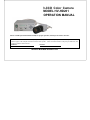
3-CCD Color Camera
MODEL HV-HD201
OPERATION MANUAL
Please read this operation manual carefully for proper operation, and keep it for future reference.
Note:
The model and serial numbers of your product are important for you to keep for your convenience and protection. These
numbers appear on the nameplate located on the bottom of the product. Please record these numbers in the spaces provided below, and
retain this manual for future reference.
Model No. Serial No.
Hitachi Kokusai Electric Inc.

A
IMPORTANT SAFETY INSTRUCTIONS
1. Read Instructions
All the safety and operating instructions should
be read before the product is operated.
2. Retain Instructions
The safety and operating instructions should be
retained for future reference.
3. Heed Warnings
All warnings on the product and the operating
instructions should be adhered to.
4. Follow Instructions
All operating and use instructions should be
followed.
5. Cleaning
Unplug this product from the wall outlet before
cleaning. Do not use liquid cleaners or aerosol
cleaners. Use a damp cloth for cleaning.
6. Attachments
Do not use attachments not recommended by the
product manufacturer as they may cause
hazards.
7. Water and Moisture
Do not use this product near water - for example,
near a bath tub, wash bowl, kitchen sink, or
laundry tub; in a wet basement; or near a
swimming pool; and the like.
8. Accessories
Do not place this product on an unstable cart,
stand, tripod, bracket, or table. The product
may fall, causing serious injury to a child or adult,
and serious damage to the product. Use only
with a cart, stand, tripod, bracket, or table
recommended by the manufacturer, or sold with
the product. Any mounting of the product
should follow the manufacturer's instructions,
and should use a mounting accessory
recommended by the manufacturer.
9. Moving
A product and cart combination should be moved
with care.
Quick stops, excessive force, and uneven surfaces
may cause the product and cart combination to
overturn.
10. Ventilation
Slots and openings in the cabinet are provided for
ventilation and to ensure reliable operation of the
product and to protect it from overheating, and
these openings must not be blocked or covered.
The openings should never be blocked by placing
the product on a bed, sofa, rug, or other similar
surface. This product should not be placed in a
B
built-in installation such as a bookcase or
rack unless proper ventilation is provided or the
manufacturer's instructions have been adhered
to.
11. Power Sources
This product should be operated only from the
type of power source indicated on the marking
label. If you are not sure of the type of power
supply to your home, consult your product dealer
or local power company. For products intended
to operate from battery power, or other sources,
refer to the operating instructions.
12. Grounding or Polarization
This product is equipped with a three-wire
grounding-type plug a plug having a third
(grounding) pin. This plug will only fit into a
grounding-type power outlet. This is a safety
feature. If you are unable to insert the plug into
the outlet, contact your electrician to replace
your obsolete outlet. Do not defeat the safety
purpose of the grounding-type plug.
13. Power-Cord Protection
Power-supply cords should be routed to that they
are not likely to be walked on or pinched by
items placed upon or against them, paying
particular attention to cords at plug, convenience
receptacles, and the point where they exit from
the product.
14. Lightning
For added protection for this product during a
lightning storm, or when it is left unattended and
unused for long periods of time, unplug it from
the wall outlet. This will prevent damage to the
product due to lightning and power-line surges.
15. Overloading
Do not overload wall outlets, extension cords or
integral convenience receptacles as this can result
in a risk of fire or electric shock.
16. Object and Liquid Entry
Never push objects of any kind into this product
through openings as they may touch dangerous
voltage points or short-out parts that could result
in a fire or electric shock. Never spill liquid of
any kind on the product.
17. Inflammable and Explosive Substance
Avoid using this product where there are gases,
and also where there are inflammable and
explosive substances in the immediate vicinity.
18. Heavy Shock or Vibration
When carrying this product around, do not
subject the product to heavy shock or vibration.

C
19. Servicing
Do not attempt to service this product yourself
as opening or removing covers may expose you to
dangerous voltage or other hazards. Refer all
servicing to qualified service personnel.
20. Damage Requiring Service
Unplug this product from the wall outlet and
refer servicing to qualified service personnel
under the following conditions:
a.When the power-supply cord or plug is
damaged.
b.If liquid has been spilled, or objects have fallen
into the product.
c. If the product has been exposed to rain or
water.
d.If the product does not operate normally by
following the operating instructions. Adjust
only those controls that are covered by the
operating instructions as an improper
adjustment of other controls may result in
damage and will often require extensive work
by a qualified technician to restore the product
to its normal operation.
e. If the product has been dropped or damaged in
any way.
f. When the product exhibits a distinct change in
performance-this indicates a need for service.
21. Replacement Parts
When replacement parts are required, be sure the
service technician has used replacement parts
specified by the manufacturer or have the same
characteristics as the original part.
Unauthorized substitutions may result in fire,
electric shock, or other hazards.
22. Safety Check
Upon completion of any service or repairs to this
product, ask the service technician to perform
safety checks to determine that the product is in
proper operating condition.
23. Wall or Ceiling Mounting
The product should be mounted to a wall or
ceiling only as recommended by the
manufacturer.
24. Heat
The product should be situated away from heat
sources such as radiators, heat registers, stoves,
or other products (including amplifiers) that
produce heat
.
D
WICHTIGE SICHERHEITSANWEISUNGEN
1. Alle Anweisungen lesen
Vor Betrieb des Erzeugnisses sollten alle
Sicherheits-und Bedienungsanleitungen gelesen
werden.
2. Die Anweisungen aufbewahren
Die Sicherheits-und Bedienungsanleitungen
sollten fünftigen Bezug aufbewahrt werden.
3. Warnungen beachten
Die Warnungen auf dem Erzeugnis und in den
Bedienungsanleitungen solten beachtet werden.
4. Anweisungen befolgen
Alle Bedienungsanleitung-und
Verwendungsanweisungen sollten befolgt werden.
5. Reinigung
Den Stecker des Geräts vor Reinigung aus der
Steckdose ziehen. Keine flüssigen Reinigungsmittel
oder Aerosolreiniger verwenden. Zum Reinigen
einen feuchten Lappen verwenden.
6. Zubehör
Nur vom-Hersteller des Erzeugnisses
empfohlenes Zubehör verwenden, da es sonst zu
Störungen kommen kann.
7. Wasser und Feuchtigkeit
Dieses Erzeugnis nicht in der Nähe von Wasser
verwenden - z.B, in der Nähe einer Badewanne,
eines Waschbeckens, einer Küchenspüle, eines
Waschzubers, in einem nassen Keller, in der Nähe
eines Schwimmbeckens usw.
8. Aufstellung
Das Erzeugnis nicht auf einen unstabilen Wagen,
Stand, Dreifuß, Träger oder Tisch stellen.
Das Erzeugnis kann sonst herunterfallen und ein
kind oder einen Erwachsenen schwer verietzen.
Außerdem kann das Gerät schwer beschädigt
werden. Nur mit einem Wagen, Stand, Dreifuß,
Träger oder Tisch verwenden, der vom Hersteller
empfohlen oder mit dem Erzeugnis verkauft
worden ist. Für jegliche Anbringung sollten die
Anweisungen des Herstellers befolgt werden, und
das vom Hersteller empfohlene Anbringungszubehör
sollte verwendet werden.
9. Eine Kombination von Erzeugnis und Wagen
sollte vorsichtig bewegt werden
Schneller Halt, übermäßige Krafteinwirkung und
unebene Oberflächen können Umkippen der
kombination von Erzeugnis und Wagen
verursachen.
10. Ventilation
Schlitze und Öffnungen im Gehäuse dienen der
Ventilation. Sie sind für zuverlässigen Betrieb
des Gerätes und Schutz vor Überhitzung

E
erforderlich und dürfen nicht blockiert oder abgedeckt
werden.
Die Öffnungen sollten niemals dadurch blockiert
werden, daß, das Gerät auf ein Bett, ein Sofa,
einen Teppich oder eine ähnliche Oberfläche
gestellt wird.
Das Gerät sollte nur dann in Einbauinstallierung
wie in einem Bücherschrank oder einem Gestell
verwendet werden, wenn angemessene
Ventilation vorgesehen ist bzw. Die
Anweisungen des Herstellers befolgt worden
sind.
11. Stromversorgung
Dieses Erzeugnis sollte nur an der auf dem
Typenschild angegebenen Stromversorgungsart
betrieben werden. Wenn Sie nicht sicher sind,
was für eine Stromversorgung Sie haben, so
wenden Sie sich bitte an Ihren Erzeugnishändler
oder an das lokale Elektrizitätswerk. Beziehen
Sie sich für Batteriebetrieb oder andere
Stromquellen vorgesehene Erzeugnisse bitte auf
die Bedienungsanleitungen.
12. Erdung oder Polarisierung
Dieses Erzeugnis ist mit einem
Schutzkontaktstecker mit drei Leitern
ausgerüstet, mit einem Erdungskontakt. Dieser
Stecker paßt nur in ein schuko-Steckdose. Dies
ist eine Sicherheitsmaßnahme. Wenn Sie den
Stecker nicht in die Steckdose stecken können, so
wenden Sie sich bitte an ihren Elektriker, damit er
die veraltete Schuts des Schutzkontaktsteckers
unwirksam.
13. Netzkabelschutz
Netzkabel sollten so verlegt werden, deß möglichst
nicht darauf getreten wird und daß sie nicht
eingeklemmt werden, mit besonderer Beachtung
der kabel an Stackern, Verlängerungskabeln und
dem Austritt des Kabels aus dem Erzeugnis.
14. Blitzschlag
Für zusätzlichen Schutz des Erzeugnisses während
eines Gewitters oder bei Nichtverwendung für
lange Zeit den Stecker aus der Steckdose ziehen.
Dies verhütet Beschädigung durch Blitzschlag und
Netzspannungsstöße.
15. Überlastung
Wandsteckdosen, Verlängerungskabel und
eingebaute Bequemlickkeitssteckdosen nicht
überlasten, da dies Feuer oder elektrischen
Schlag verursachen kann.
F
16. Eindringen von Fremdkörpern und Flüssigkeit
Niemals Objekte irgendwelcher Art durch die
Öffnungen in das Gerät schieben, da diese unter
hoher Spannung stehende Teile berühren oder
kurzschließen können, wodurch es zu Feuer oder
elektrischem Schlag kommen kann. Niemals
Flüssigkeiten irgendwelcher Art auf das
Erzeugnis verschütten.
17. Entflammbare und explosive Substanzen
Vermeiden Sie Verwendung dieses Erzeugnisses
an Orten mit Gasen bzw. entflammbaren oder
explosiven Substanzen in der direkten
Umgebung.
18. Starke stöße oder Vibrationen
Setzen Sie das Erzeugnis beim Transport nicht
starken Stößen oder Vibrationen aus.
19. Wartung
Versuchen Sie nicht, dieses Erzeugnis Selbst zu
warten, da Sie sich durch Öffnen bzw.
Entfernen von Abdeckungen hohen Spannungen
und sonstigen Gefährdungen ausserzen können.
Beziehen Sie sich für jegliche Wartung auf
qualifiziertes Wartungspersonal.
20. Beschädigung, die Wartung erfordert
Ziehen Sie den Stecker dieses Erzeugnisses aus
der Steckdose und wenden Sie sich an
qualifiziertes Wartungspersonal, wenn eine der
folgenden Bedingungen vorliegt:
a. Wenn das Netzkabel oder der Stecker
beschädigt ist.
b. Bei Eindringen von Flüssigkeit oder
Fremdkörpern in das Gerät.
c. Wenn das Erzeugnis Regen oder Wasser
ausgesetzt worden ist.
d. Wenn das Erzeugnis bei Befolgen der
Bedienungsanleitungen nicht normal
funktioniert.
Nur die Regelelemente verstellen, die in den
Bedienungsanleitungen behandelt werden, da
unangemessene Einstellung anderer
Regelelemente Beschädigung verursachen kann
und oft beträchtliche Arbeit durch einen
qualifizierten Techniker erfordert, um das
Erzeugnis wieder, zu normalem Betrieb
zurückzubringen.
e. Wenn das Erzeugnis fallen gelassen oder
beschädigt worden ist.
f. Wenn das Erzeugnis eine klare Änderung in
der Leistung zeigt-dies weist darauf hin, daß
Wartung erforderlich ist.

G
21. Ersatzteile
Wenn Ersatzteile erforderlich sind, darauf
achten, daß der Wartungstechniker nur die vom
Hersteller festgelegten Ersatzteile oder Teile mit
den gleichen Charakteristiken wie die
ursprünglichen Teile verwendet. Unautorisierte
Ersatzteile können Feuer, elektrischen Schlag
oder sonstige Gefährdungen verursachen.
22. Sicherheitsprüfung
Bitten Sie den Wartungstechniker nach der
Vollendung von Wartung oder Reparaturarbeiten
an diesem Erzeugnis um die Durchführung von
Sicherheitsprüfungen, um zu bestimmen, daß das
Erzeugnis im angemissenen Betriebszustand ist.
23. Anbringung an der Wand oder an der Decke
Das Erzeugnis sollte nur entsprechend den
Empfehlungen des Herstellers an einer Wand
oder an der Decke angebracht werden.
24. Wärme
Das Erzeugnis sollte fern von Wärmequellen wie
Radiatoren, Heizwiderständen, Öfen und
anderen Wärme erzeugenden Erzeugnissen
(einschließlich Verstärkern) aufgestellt werden.
H
MISES EN GARDE IMPORTANTES
1. Lire les instructions
Lire toutes les instructions de sécurité et de
fonctionnement avant de faire fonctionner
l’appareil.
2. Conserver ces instructions
Conserver les instructions de sécurité et de
fonctionnement á des fins de référence ultérieure.
3. Tenir compte des avertissements
Tous les avertissements qui figurent sur
l’appareil et dans le mode d’emploi devront être
respectés.
4. Observer les instructions
Observer toutes les instructions de
fonctionnement et d’utilisation.
5. Nettoyage
Avant de procéder au nettoyage, débrancher
l’appareil de la prise secteur. Ne pas utiliser
de produits de nettoyage liquides ou en aérosol.
Nettoyer l’appareil avec un chiffon humide.
6. Fixations
Ne pas utiliser de fixations non recommandées
par le fabricant de l’appareil car elles
pourraient être source de danger.
7. Eau et humidité
Ne pas utiliser l’appareil á proximité d’eau-ar exemple
prés d’une baignoire, d’un lavabo, d’un évier ou
d’un bac á lessive, dans un sous-sol humide, ou
prés d’une piscine, etc.
8. Accessoires
Ne pas placer l’appareil sur un chariot, un socle,
un pied, un support ou one table instables
L’appareil pourrait tomber, blessant griévement
des enfants ou des adultes, et étant sérieusement
endommagé.
Utiliser exclusivement le chariot, le socle, le pied,
le support ou la table recommandés par le
fabricant, ou vendus avec l’appareil. Pour tout
montage de l’appareil, respecter les instructions
du fabricant, et utiliser á cette fin l’accessoire de
montage recommandé par le fabricant.
9. L’appareil monté sur son chariot devra être
déplacé avec précaution
Des arrêts brusques, une force excessive et des
surfaces irréguliéres pourraient provoquer le
renversement de l’ensemble appareil-chariot.
10. Ventilation
Les fentes et les ouvertures du coffret sont
prévues pour la ventilation ainsi que pour
garantir un fonctionnement en toute sécurité de

I
l’appareil et le protéger de toute surchauffe, et
ces ouvertures ne devront donc être ni
obstruées ni recouvertes. Ne jamais obstruer les
ouvertures en placant l’appareil sur un lit, un
sofa, un tapis ou toute surface similaire. Ne
jamais placer l’appareil dans un support confiné,
par exemple une bibliothéque ou une é tagé re,
sans ventilation suffisante ou sans repecter les
instructions du fabricant.
11. Sources d’allmentation
L’appareil devra être alimenté exclusivement sur
le type d’alimentation indiqué sur l’étiquette
signalétique. Sil’on n’est pas sûr du type
d’alimentatio du local, consulter le revendeur de
l’appareil ou la compagnie d’électricité locale.
Pour les appareils qui fonctionnent sur batterie
ou sur d’autres sources, voir le mode d’emploi.
12. Mise á la terre ou polarisation
L’appareil est doté d’une fiche trifilaire avec mise
á la terre, dont la troisiéme broche assure la mise
á la terre. Cette fiche ne rentrera que dans les
prises trifilaires de mise á la terre. Ceci est une
mesure de sécurité. Si la fiche ne rentre pas
dans la prise, faire remplacer la prise désuéte par
un électricien.
Ne pas rendre vaine la measure de sécurité
assurée par cette prise avec mise á la terre.
13. Protection du cordon d’alimentation
Acheminer les cordons d’alimentation de facon
qu’on ne risque pas de marcher dessus ou de les
coincer sous un objet placé dessus ou contre eux.
Faire particuliérement attention aux fiches des
cordons, á la proximité des prises, et á l’endroit oú
ils ressortent de l’appareil.
14. Foudre
Pour renforcer la protection de l’appareil pendant
un orage, ou si l’on s’en éloigne ou qu’on reste
longtemps sans l’utiliser, le débrancher de la
source d’alimentation. Ceci permettra d’éviter
tout dommage de l’appareil dú á la foudre et aux
surtensions de ligne.
15. Surcharge
Ne pas surcharger les prises, rallonges et prises
multiples car cela pourrait entraîner un risque de
feu ou de choc électrique.
16. Pénétration d’objets et de liquides
Ne jamais enfoncer d’objets d’aucune sorte dans
les ouvertures de l’appareil car ils pourraient
toucher des points de tension dangereuse ou
court-circuiter des piéces, ce qui pourrait
J
provoquer un feu ou un choc électrique. Ne
jamais renverser de liquide d’aucune sorte sur
l’appareil.
17. Substances inflammabes et explosives
Eviter d’utiliser l’appareil en présence de gaz,
ainsi qu’á proximité immédiate de substances
inflammables et explosives.
18. Chocs ou vibrations violents
Lorsqu’on transporte l’appareil, ne pas le
soumettre á des chocs ou des vibrations violents.
19. Réparations
Ne pas tenter de réparer l’aapareil soi-même car
le fait d’ouvrir ou de retirer les caches risque
d’exposer l’utilisateur á des tensions dangereuses
notamment. Confier toute réparation á un
personnel qualifié.
20. Dommages nécessitant réparations
Débrancher l’appareil de la source d’alimentation
et confier les réparations á un personnel qualifié
dans les cas suivants:
a. Lorsque le cordon d’alimentation ou sa fiche
sont endommagés
b. Si du liquide s’est renversé sur l’appareil ou
que des objets sont tombés dedans
c. Si l’appareil a été exposé á la pluie ou á l’eau.
d. Si l’appareil ne fonctionne pas normalement
lorsqu’on observe les instructions d’utilisation.
Ne régler que les commandes couvertes par le
mode d’emploi ; en effet, un réglage incorrect
des autres commandes pourrait entrainer des
dommages et nécessiteront souvent des travaux
de réparation coûteux par un technicien qualifié
pour remettre l’appareil en état de marche.
e. Si l’appareil est tombé ou qu’il a été
endommagé.
f. Si l’appareil affiche une nette modification de
ses performances, cela signifie qu’il a besoin
d’être réparé.
21. Piéces de rechange
Si l’on a besoin de piéces de rechange, veiller á ce
que le technicien de réparation utilise
exclusivement les piéces de rechange spécifiées
par le fabricant ou des piéces ayant les mêmes
caractéristiques que les piéces d’origine. Les
piéces de rechange non autorisées risquent de
provoquer un feu, un choc électrique et autres
dangers.

K
22. Vérificaton de sécurité
Aprés tout travail d’entretien ou de réparation de
l’appareil, demander au technicien de réparation
d’effectuer les vérifications de sécurité pour
s’assurer que l’appareil est en bon état de
marche.
23.Montage au mur ou au plafond
L’appareil ne pourra être monté au mur ou au
plafond que de la maniére recommandée par le
fabricant.
24. Chaleur
Eloigner l’appareil des sources de chaleur, telles
que radiateurs, appareils de chauffage,
cuisiniéres, et de tour produit engendrant de la
chaleur (y compris les amplificateurs).
L
IMPORTANT NOTICE
These products have been tested and found to
comply with the limits for a Class A digital
device, pursuant to Part 15 of the FCC Rules.
These limits are designed to provide
reasonable protection against harmful
interference when the equipment is operated
in a commercial environment. This
equipment generates, uses, and can radiate
radio frequency energy and, if not installed
and used in accordance with the instruction
manual, may cause harmful interference to
radio communications. Operation of this
product in a residential area is likely to cause
harmful interference in which case the user
will be required to correct the interference at
his own expense.
WARNING
Changes or modifications not expressly
approved by Hitachi Kokusai Electric
responsible for compliance could void the
user’s authority to operate the equipment.
This product does not exceed the class A/class
B limits for radio noise emissions from digital
apparatus as set out in the radio interference
regulations.
Le présent appareil n’émet pas de bruits
radioélectriques dépassant les limités
applicable aux appareils numériques de classe
A prescrites dans le rVglement sur le
brouillage radioélectrique édicter par le
ministére des communications du canada.
For USA
For Canada

M
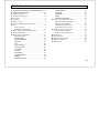
Table of contents
IMPORTANT SAFETY INSTRUCTUIONS····A
IMPORTANT NOTICE ······························· L
Table of contents······································· M
Standard composition ································ 1
Overview ················································· 1
Features ·················································· 2
Notes to users ·········································· 3
Name and function each section ··················· 5
Lens ························································· 7
Lens selection········································· 7
Flangeback adjustment ·························· 8
Video signal type lens adjustment ··············· 9
Camera mounting ·····································10
Menu Screen Operation······························11
Menu Structure ·····································11
MAIN MENU········································14
GAIN/SHUTTER ···································16
DETAIL ···············································19
ALC ···················································20
AUTO SETUP ······································22
SPECIAL SET·······································23
FILE SET ·············································24
LEVEL·················································25
MASKING ···········································27
GAMMA/KNEE ····································32
DETAIL ··············································34
COLOR DETAIL ··································36
AUTO WHITE ····································· 38
SYSTEM ············································ 40
ID/TITLE ············································ 42
LENS ················································· 44
OTHER FUNCTION······························ 46
How to Attain Better images ······················ 47
White Balance Adjustment ····················· 47
Real time Auto White····························· 49
Auto Shading Correction ························ 49
ALC (Auto level control) ························ 51
RC-Z3 remote control panel························ 52
RC-Z3 panel facilities····························· 53
Menu screen composition························ 59
Connectors··············································· 60
Specifications ··········································· 64
Input/Output Signals ································ 66
Major accessories······································ 69
Dimensions·············································· 69

1
Standard composition
Check when unpacking.
Camera, HV-HD201 ····························· 1
Power plug, R03-P3F (JPR0034*) ··········· 1
Lens plug, E4-191J-100(JPE0001*) ········ 1
Operation Manual································ 1
* Part code
Overview
The HV-HD201 is a three CCD HDTV camera
combining high picture quality and high stability
with the convenience of C mount optics. CCD size
is 1/2-size and each consists of 1,500,000 picture
elements.
Signal processing is all digitalized.
High quality signal processing and image
compensating functions are attained by Hitachi's
unique digital processing technology condensed
into an advanced FPGA chip while power
consumption is remarkably reduced by
employing the latest CCD and digital process
technologies.
It provides
the digital output of high-definition
television format of four modes as well as the
analog signal output of HD/SD format, and the
image can be used all over the world. Similar to
the existing HV-D series products, both image
signals can be output concurrently without using
any option.
2
Features
C mount
The camera uses a C mount lens, which is the de
facto standard in the industry. A built-in
flangeback adjusting mechanism allows use with
different types of optical systems.
Note : We recommend using a HDTV lens for
obtaining full performance from the camera.
Multiple Formats
HDTV : The image can be outputted in four kinds
of modes, that is 1080i(59.94 fields or 50 fields) or
720p(59.94 frams or 50 frames).
SDTV : 576i(50 fields) or 480i(59.94 fields) can be
outputted.
In eight kinds of total modes, the HDTV/SDTV
image can be outputted.
Note :
The SDI output supports only HDTV.
Auto shading compensation (ASC)
Color shading incurred when using a C mount
lens is automatically compensated (attenuated).
Two modes of shading are provided and can be
selected according to the cameras application, a
vertical color shading mode or a two-dimensional
luminance-shading mode.
Bi-directional data communication
The camera can be connected to a personal
computer via RS-232C for two-way data
communications to provide finely detailed
camera control. An identification (ID) code can
be assigned to each camera in a system and allow
remotely controlling multiple cameras from a
single computer.

3
Notes to users
Important safety notes
Use this camera with a 12 VDC power supply.
Observe that flammable objects, water or metal
do not enter the camera interior. These may
lead to failure or accident.
Do not modify the camera or use the camera with
external covers removed. These may cause
failure, void any warranties and pose a safety
hazard.
Stop using the camera at the approach of an
electrical storm (thunder audible). Protect the
camera from rain if using it outdoors.
In event the camera shows any abnormality,
switch off the camera and disconnect the power
cord. Contact a Hitachi Kokusai Electric service
representative.
Operating considerations
Power supply
Check that the supplied voltage is between 10.5
and 15 VDC. Inadequate voltage can affect
color fidelity and cause noise, while voltage over
15 V can damage the camera.
Connectors
Confirm the power is off before connecting or
disconnecting a signal cable. Grasp connectors
by the body, not the attached wires.
Lens
The correct lens is important for deriving
optimum performance from the camera.
Consult a Hitachi Kokusai Electric dealer for a
selection of fine lenses according to the
application.
Installation and storage sites
The following types of environment can impair
performance, lead to damage, pose safety
hazards and shorten the useful life of the camera.
Select the sites for installing the storing the
camera carefully.
• Direct sunlight, rain or snow
• Flammable or corrosive gasses
• Very hot or cold (beyond -10 to 40 ℃
operating, -20 to 60 ℃ storage)
• Humid or dusty
• Exposed to vibration or shock
• Strong electrical or magnetic fields
• Exceptionally strong light
Continuous operation
In situations where the camera is used
continuously for long periods of time, the
ambient temperature should be kept below 40 ℃
in order to avoid accelerated deterioration of
internal parts and to derive maximum long-term
reliability.
4
Cleaning
A photographer’s blower or lens brush can be
used for clearing dust from the lens and optical
filters.
Wipe dust from the case with a soft dry cloth. If
soiling is severe, moisten the cloth with a
solution of neutral detergent. Afterwards, wipe
the cover with a dry cloth.
Do not use petroleum distillates, alcohol or spray
type cleaners.
Transportation
Remove the lens (install lens mount cap) and
other attachments. Pack the camera carefully
in its original or equivalent container. Use
ample cushioning to protect the camera from
physical shock.

5
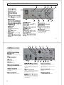
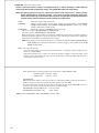
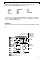
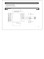
Name and function each section
6
It set the operational mode of HDTV.
Please change it at power off state.)
Please change it at power off state.)
Outputs HD-SDI signal.
Outputs Y/C signal.
Outputs VBS signal.
Inputs SYNC signal of HDTV for external
synchronization.
The camera cable linked to a camera head
is connected.
Sets the signal level to connect to
REMOTE terminal. (Please set it to
-3 when camera is connected with
r e m ot e c o nt r o l b ox m a de by ou r
company.)
Used for connection with the remote
control box RC-Z3 or personal computer
to remote control the camera.
It inputs or outputs the HD/VD signal
o f m u l t i c o nn e c t o r f o r ex t e rn al
synchronization.
O u t p u t s t h e a n a l o g p i c t u r e
signal/synchronization signal.
(Please refer to the connector terminal
figure for details.
Connects the iris connector of an auto
iris lens.
Outputs the HDTV picture signal.
The 12V power supply is connected.

7
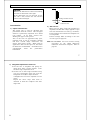
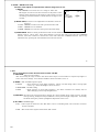
Lens
CAUTION:
Observe the dimensions of the lens mounting
selection as illustrated at the right.
If the dimensions are not observed, do not
use such a lens, because the lens and the
camera will be damaged.
Lens selection
1) Optical characteristics
The proper lens is vital for obtaining full
performance from the camera. The exit pupil
distance is particularly important for a 3CCD
type camera. If too short, vertical color
shading can appear in the picture.
Also, as the lens iris approaches fully open,
problems such as loss of resolution, shading
and flare (overall image "white-out") can
detract from picture quality. When using in
applications that call for open iris, the lenses
for 3CCD are recommended. If another lens is
contemplated, check the performance
beforehand.
2) Auto iris lens
Main types are Video (with self contained iris
amplifier) and DC (DC voltage applied to open
lens iris) and manual over-ride (e.g., Cosmicar).
Lenses without self-contained iris amplifier are
not compatible.
Camera settings differ according to the auto
iris lens type (see page 44).
Note: The HV-HD201 uses lens connector wiring
prescribed by the EIAJ (Electronic
Industries Association of Japan). Refer to
page 61.
Flange surface of lens
4.0mm or less
8
3) Flangeback adjustment of zoom lens
1) Set the lens to telephoto and pickup an
image more than 3 meters distant. Turn
the focus ring to adjust the focus.
2) Set the lens to wide angle and while using
care not to disturb the focus ring, turn the
flangeback screw(※) to adjust the focus.
A flangeback screw can be adjusted at a flat
driver.
Repeat the above steps until focus is
obtained at both the telephoto and wide
angle ends.

9
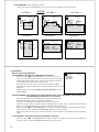
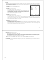
Video signal type lens adjustment
Adjustment is required after replacing the lens or
if using the camera for the first time.
1) Preparation
(1) Gain in the GAIN/SHT. manu is set to
PRESET, and PRESET under that is set to
+0dB.
(2) If the light source has a flicker component
(e.g., fluorescent or mercury lighting),
change the electronic shutter mode (GAIN/
SHT. menu Shutter or Variable) to reduce
the flicker.
(3) Adjust the white balance. (Page 22)
2) Adjustment
Hold the U button depressed and press Setup for
about 2 seconds to display the Special Set menu.
Change to the Lens screen and check the Lens
Type setting. If DC, change this to Video.
(1) Set the lens ALC control fully toward the
average (Av ) position.
(2) If auto iris hunting occurs, reduce the Iris
Gain setting.
(3) Adjust the lens level control to where the
center quadrangle is positioned at the video
signal level indicator cross mark.
If the camera video signal detection level is
optimum,the quadrangle mark is center. If
larger than optimum,the quadrangle marker
to the right of H is moved and if lower,the
quadrangle mark to the left of L is moved.
3) Lens adjustment difficult or impossible
(1) Video signal level indication unstable
Unstable indication can occur if the light
source has a flicker component ( e. g.,
fluorescent or mercury lighting), change the
electronic shutter mode (GAIN/SHT. menu
shutter or Variable ) to reduce the flicker.
(2) Lens Level control fully at Hi, but auto iris
inoperative Reduce the Iris Gain setting.
(3) Lens Level control fully at Low, but auto iris
inoperative Increase the Iris Gain setting.
10
(4) Auto iris operates, but scene is dark. Even
if lens Level control is adjusted , the
quadrangle mark to the left of the H mark is
moved.
Boost the gain. Set GAIN/SHT. menu
GAIN to 1- 12 dB in order to raise the
sensitivity.
Note:
The video signal level indicator sensitivity is
high in order to increase lens adjustment
accuracy. Operate the lens Level control
slowly.
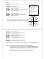
Camera mounting
The camera is provided with threaded screw holes
at the top and bottom. These allow mounting to
either a tripod or a mounting bracket.
Screw type: U 1/4-20
Length: 4.5 to 6 mm
L
Screws longer than 6 mm can
cause internal damage, while
less than 5 mm prevents secure
fastening and risks dropping to
cause damage and injury.

11
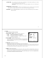
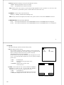
Menu Screen Operation
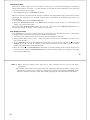
1. Menu Structure
For settings in the camera, the MAIN and SPECIAL menus are available.
1) MAIN Menu Structure
Press the MENU button and MAIN MENU appears on the screen to indicate the main menu mode. Again
press the MENU button to extinguish the menu and enter the direct mode. There are a main function setup
menu and four sub-menus, which are arranged hierarchically as shown below. On the MAIN MENU, bring
the cursor to GAIN/SHUTTER, DTL, ALC or AUTO SETUP and press the R button, and the desired
subsidiary menu will come up. To return to the MAIN MENU from the GAIN/SHUTTER, DETAIL, ALC or
AUTO SETUP, bring the cursor to the top line (title line of GAIN/ SHUTTER,, DTL, ALC or AUTO SETUP)
and press the L button.
On each menu screen, bring the cursor to any desired item using the U or D button. For mode change/data
setting, use the L or R button.
MAIN MENU [FILE 1]
CAMERA MODE :MANUAL
WHITE BALANCE :MEMORY
MASTER BLACK : 0
GAIN/SHUTTER :NEXT [PUSH R]
DETAIL :NEXT [PUSH R]
ALC :NEXT [PUSH R]
AUTO SETUP :NEXT [PUSH R]
FILE SELECT:FILE1
GAIN/SHUTTER [FILE 1]
[GAIN] :NORM
NORM :+ 0 DECIBEL
HIGH :+ 6 DECIBEL
MAX :+12 DECIBEL
AGC LIMIT :+ 6 DECIBEL
SHUTTER :OFF
SHUTTER OFF :[1/60]
AES OFFSET :OFF
CCD MODE :FIELD
DETAIL [FILE 1]
DETAIL : 0
DETAIL FREQ. :STANDARD
H/V BALANCE : 0
ALC [FILE 1]
OVER RIDE : 0
SPEED :STANDARD
PEAK/AVE :15/85
ALC GATE :OFF
GATE SEL :PATTERN1
AUTO SETUP [FILE 1]
AUTO WHITE
AUTO SHADING
AUTO BLACK
12
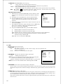
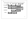
2) SPECIAL Menu Structure
To select the SPECIAL SET mode, press the MENU button for 2 seconds while holding down the U button.
Thus, the SPECIAL SET menu can be displayed. To return to the DIRECT mode, press the MENU button
again. The SPECIAL SET menu indicates a list of items, and each special items subsidiary menus are
available. These menus are arranged hierarchically as shown below. To return to the SPECIAL SET menu,
bring the cursor to the top line (title line of each subsidiary menu) and press the L button.
On each menu screen, bring the cursor to any desired item using the U or D button. For mode change/data
setting, use the L or R button.
SPECIAL SET
FILE SET :NEXT [PUSH R]
LEVEL :NEXT [PUSH R]
MASKING :NEXT [PUSH R]
GAMMA/KNEE :NEXT [PUSH R]
DETAIL :NEXT [PUSH R]
AUTO WHITE :NEXT [PUSH R]
SYSTEM :NEXT [PUSH R]
ID/TITLE :NEXT [PUSH R]
LENS :NEXT [PUSH R]
OTHER FUNCTION :NEXT [PUSH
R]
TIME/DATE :NEXT [PUSH R]
MASKING [FILE1 ]
[HUE][SAT] [LINEAR]
R : 0 0 R-G: 0
Y-R: 0 0 R-B: 0
Y : 0 0 G-R: 0
G-Y: 0 0 G-B: 0
G : 0 0 B-R: 0
C-G: 0 0 B-G: 0
C : 0 0
B-C: 0 0
B : 0 0 MASTER SAT: 0
M-B: 0 0 ON/OFF :OFF
M : 0 0
R-M: 0 0
INITILIZE :[PUSH L+R] 2SEC
LEVEL [FILE1 ]
ENABLE :OFF
R GAIN : 0
B GAIN : 0
R BLACK : 0
B BLACK : 0
INITIALIZE :[PUSH L+R] 2SEC
GAMMA/KNEE [FILE1 ]
GAMMA :ON
GAMMA TABLE :STANDARD
TOTAL GAMMA : 0
R GAMMA : 0
B GAMMA : 0
KNEE :AUTO
KNEE POINT : 0
WHITE CLIP : 0
INITIALIZE :[PUSH L+R] 2SEC
DETAIL [FILE1 ]
DETAIL FREQ. :MID
HIGH CHROMA :OFF
LEVEL DEP. :-110
CRISP :-110
SOFT DETAIL W. :-118
SOFT DETAIL B. :-118
H/V BALANCE : 0
COLOR DETAIL :NEXT [PUSH R]
INITIALIZE :[PUSH L+R] 2SEC
COLOR DETAIL [FILE1 ]
COLOR DETAIL :OFF
CH1 A.PHASE :[PUSH R] 1SEC
PHASE : 0 YE-R
WIDTH : 0
LEVEL :-128
CH2 A.PHASE :[PUSH R] 1SEC
PHASE : 0 YE-R
WIDTH : 0
LEVEL :-128
INITIALIZE :[PUSH L+R] 2SEC
FILE SET
FILE SELECT :FILE1
STORE FILE :FILE2
STORE :
---- SD CARD MEMORY ----
[SAVED FILE :2009-05-18 14:43]
SAVE DATA :[PUSH R] 1SEC
LOAD DATA :[PUSH R] 1SEC
ALL INITIALIZE :[PUSH L+R] 2SEC

13
SYSTEM
ANALOG OUT SEL:HD TV
RGB/Y PB PR :RGB
OUTPUT SYNC :SYNC
H PHASE : 0
GL IN :75 OHM
REMOTE : 9600 BPS
MESSAGE RTN :ON
AUTO WHITE [FILE1 ]
SPEED :STANDARD
HIGH LIMIT :10000K
LOW LIMIT :2500K
WHITE GATE :OFF
GATE AREA H : 4
GATE AREA V : 2
INITIALIZE :[PUSH L+R] 2SEC
ID/TITLE
ID :OFF
TITLE :OFF
DATA SET :NEXT [PUSH R]
DATA SET
ID :
TITLE :
1234567890? :
ABCDEFGHIJKL
MNOPQRSTUVWX
YZ[]+-x/.,
L- R- DEL INS RET
LENS
LENS TYPE :VIDEO
? IRIS MODE :---
? IRIS SPEED :---
? OPEN LIMIT :---
? CLOSE LIMIT :---
IRIS GAIN : 0
INITIALIZE :[PUSH L+R] 2SEC
L H
TIME/DATE
[2009-01-18. 13:42:36 ]
YEAR :2009
MONTH : 3
DATE : 3
HOUR : 13
MINUTE : 42
SET DATA : [PUSH R]
OTHER FUNCTION
DYNAMIC CHROMA:OFF
FLARE :ON
FLARE LEVEL : 0
DNR :ON
INITIALIZE :[PUSH L+R] 2SEC
14
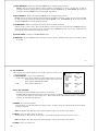
2. MAIN MENU
It is the menu of a function used most frequently.
1) CAMERA MODE : Camera mode
•
MANUAL : Nearly all function modes can be set. Use for detailed settings.
•
AUTO : Video level and white balance are automatic and a standard picture cam be observed
without detailed settings.
“レ”indicates a fixed setting and the cursor jumps to the next item. The Auto indication flashes when a
function is related to the auto mode.
MENU Function and Mode
WHITE BALANCE
AUTO
AGC
ON
SHUTTER
AES
KNEE
AUTO
GAMMA
ON
MAIN MENU [FILE 1]AUTO
CAMERA MODE :AUTO
レWHITE BALANCE :MEMORY
MASTER BLACK : 0
GAIN/SHUTTER :NEXT [PUSH R]
DETAIL :NEXT [PUSH R]
ALC :NEXT [PUSH R]
AUTO SETUP :NEXT [PUSH R]
FILE SELECT:FILE1
Flashing
A fixed setting

15
2) WHITE BALANCE : White balance mode
Hue adjustment according to the color temperature of illumination so that a white image is picked up
when the subject is white.
•
PRST 3200K : The white balance condition is optimized at a color temperature of 3200K.
•
PRST 5600K : The white balance condition is optimized at a color temperature of 5600K.
•
MEMORY : White balance is automatically adjusted by the direct mode AWB button.
•
AUTO : The white balance condition is set through real time auto white balancing
(automatic tracking white balance).
The adjustment speed can be selected with SPEED of AUTO WHITE menu.
3) MASTER BLACK : Master black level setting
Adjustment of black brightness.
Used when black portions are whitish or black saturations occur.
The master black level can be set in a range of
-
128 to 127. Pressing the R button increases a set value
to make the black level higher, and pressing the L button decreases a set value to make the black level
lower. For zero (0) setting, hold down both the L and R buttons for approx. one seconds.
4) GAIN/SHUTTER :
The GAIN/
SHUTTER
is brought up.
5) DETAIL
: The DETAIL is brought up.
6) ALC
: The ALC is brought up.
7) AUTO SETUP
: The AUTO SETUP is brought up.
8) FILE SELECT : Select among scene files 1, 2, 3, and 4.
Camera setting data can be stored in four scene files. To shoot several scenes with different shooting
conditions, it is needed to change settings suitable for each scene. To reduce such troublesome operations,
various shooting conditions can be memorized previously to scene files, and the conditions most suitable for
a scene can be read and set.
16
In addition, scene file can also be changed by pressing SCENE FILE SELECT button of the front panel.
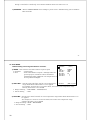
3. GAIN/SHUTTER
Scene brightness-related menu.
1) GAIN: Function to make the image brighter by electrically amplifying the image signal.
It is not preferable to raise the gain more than required noise is also amplified.
[GAIN ]
: State of the GAIN switch of the front panel.
•
NORM : Electric sensitivity(0 to 18dB) is set when the GAIN switch is at the
postion of NORM.
•
HIGH : Electric sensitivity(1 to 17dB) is set when the GAIN switch is at the
postion of HIGH.
•
MAX : Electric sensitivity(2 to 18dB) is set when the GAIN switch is at the
postion of MAX.
( MAX can not be set less than HIGH )
•
AUTO : Gain is adjusted automatically to compensate for scene brightness.
The adjustment range is set by Limit from +6 to +12 dB in 1 dB steps.
Note:
In the CAM MODE:AUTO, GAIN is fixed at AGC.
GAIN/SHUTTER [FILE 1]
[GAIN] :NORM
NORM :+ 0 DECIBEL
HIGH :+ 6 DECIBEL
MAX :+12 DECIBEL
AGC LIMIT :+ 6 DECIBEL
SHUTTER :OFF
SHUTTER OFF :[1/60]
AES OFFSET :OFF
CCD MODE :FIELD

17
2) SHUTTER
: Electronic shutter mode
Used to reduce the amount of light to an appropriate level or reduce the degree of after-image by
reducing the time of light reception per image. Using SHUTTER makes the image darker.
(Note) If a blinking light source such as a fluorescent lamp is used, flicker occurs. Setting a slower
shutter speed improves immunity to flicker. In the case of inverter fluorescent lamps, their
flickers are not like to give influence because they blink at high frequency although the flickers
of some inverter fluorescent lamps include low frequency components.
•
OFF : Electronic shutter does not operate.
•
PRESET : Shutter operates at the Preset speed. Select speed from among 1/100 (FRAME
FREQ:59.94Hz MODE), 1/60 (FRAME FREQ:50Hz MODE), 1/250, 1/500, 1/1000,
1/2000, 1/4000 and 1/10000 second.
•
VARIABLE : The shutter speed is VARIABLE value under a line.
1/60.10 to 1/11238 : (FRAME FREQ : 59.94Hz MODE)
1/50.22 to 1/9375 : (FRAME FREQ : 50Hz MODE)
When an image of a subject display screen having a different scan frequency is taken, a bright or
dark horizontal bar appears to roll up or down the screen. The shutter speed can be adjusted to
where the horizontal bars are minimized in the display.
Note :
If the display screen scanning frequency is less than 60.74Hz (50.64Hz in FRAME FREQ :
50Hz MODE), the rolling horizontal bars cannot be stopped. Not settable in the CAM
MODE : AUTO mode.
•
AES : Auto electronic shutter
Auto electronic shutter (auto electronic mode) operates. Its shutter speed is limited by the
limits set to AES LIMIT.
Appropriate image level is output even when the amount of light is excessively high. This
function can be used effectively with a microscope having no automatic light adjustment or a
system with a fixed lens iris.
18
Limit specification is setting possible in the range below. (AES OFFSET : OFF)
[59.94Hz mode] 1/60.42 to 1/5619
[50Hz mode] 1/50.40 to 1/4687
AES OFFSET
Where fluorescent lamps are driven at 50 Hz, it is sometimes possible to improve immunity to
flicker by setting 1/100 as the slowest allowable shutter speed for AES.
If a value larger than 1/100 is set as the slowest allowable shutter speed, SHUTTER is turned
off unless the amount of light into the camera is excessively high.
AES OFFSET : ON [59.94Hz mode] 1/100 to 1/5619
AES OFFSET : ON [50Hz mode] 1/60 to 1/4687
Note :
In the CAM MODE : AUTO, SHUTTER is fixed at AES.

19
4. DETAIL
:
::
:
DETAIL level setup
Contours of the subject are emphasized to make the image easier to see.
1) DETAIL
The DETAIL level can be set to in a range of -128 to 127.
The degree of contour correction increases in the positive value
setting, and it decreases in the negative value setting. For zero
(0) setting, hold down both the L and R buttons for approx. two
seconds.
2) DETAIL FREQ
: Contours to be emphasized are biased in terms of
fineness.
•
LOW : DETAIL level decrease and a picture becomes soft.
•
MID : DETAIL level is standard.
•
HIGH : DETAIL level increase and a picture becomes sharp.
3) H/V BALANCE
: Balance setting for horizontal and vertical detail amount
Setting range is -128 to +127. Press the R button to increase the value and reduce the H DETAIL
amount. Press the L button to decrease the value and reduce the V DETAIL amount. Set to 0 by
simultaneously pressing the L and R buttons for about 2 seconds.
DETAIL [FILE 1]
DETAIL : 0
DETAIL FREQ. :STANDARD
H/V BALANCE : 0
20
5. ALC
ALC is for brightness control functions Auto Iris, AGC and AES.
1) OVER RIDE
: Auto iris level setting
ALC level setting in range of
-
128 to 127 (about ±2 F stops). Press R and L for respectively higher or
lower video level settings. Press both L and R for about 2 seconds to set to 0.
2) SPEED
: AGC and AES response speed
•
SLOW : Slow response to scene light variations. Allows a stable image when a strong light
source, e.g., vehicle headlights, enters the scene.
•
STANDARD : Normal setting
•
FAST : Quick response to scene light variations. Use where variations are sudden, such as
when changing a microscope magnification.
3) PEAK/AVE
: Set auto level control for Peak or Average in 4 steps of 50/50, 25/75, 18/85 or 0/100. At high
Average setting, background may be difficult to see in picture bright components. Increasing
the Peak setting may render spotlighted components easier to see.
4) ALC GATE
: ON/OFF toggle
•
ON : Video signal is detected in the ALC Gate area for controlling AGC, lens and auto electronic
shutter and ALC.
•
OFF : The overall video signal is detected for ALC control

21
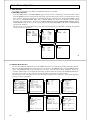
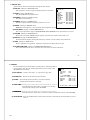
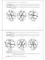
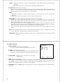
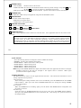
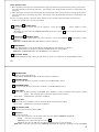
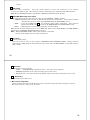
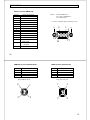
5) ALC GATE SEL
: Select ALC gate pattern
Select pattern from among Modes 1, 2, 3, 4, 5 and 6. Use according to scene conditions.
検出領域
ALC [FILE1 ]
OVER RIDE : 0
SPEED :STANDARD
PEAK/AVE :15/85
ALC GATE :ON
GATE SEL :
PATTERN 1
ALC [FILE1 ]
OVER RIDE : 0
SPEED :STANDARD
PEAK/AVE :15/85
ALC GATE :ON
GATE SEL :
PATTERN 3
ALC [FILE1 ]
OVER RIDE : 0
SPEED :STANDARD
PEAK/AVE :15/85
ALC GATE :ON
GATE SEL :
PATTERN 4
ALC [FILE1 ]
OVER RIDE : 0
SPEED :STANDARD
PEAK/AVE :15/85
ALC GATE :ON
GATE SEL :
PATTERN 5
ALC [FILE1 ]
OVER RIDE : 0
SPEED :STANDARD
PEAK/AVE :15/85
ALC GATE :ON
GATE SEL :
PATTERN 6
ALC [FILE1 ]
OVER RIDE : 0
SPEED :STANDARD
PEAK/AVE :15/85
ALC GATE :ON
GATE SEL :
PATTERN 2
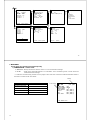
PATTERN 1
PATTERN 2 PATTERN 3
PATTERN 4
PATTERN 5
PATTERN 6
22
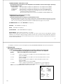
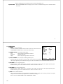
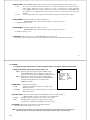
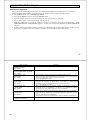
6. AUTO SETUP
Menu for initial image adjustment
1) AUTO WHITE: Color drift due to illumination is corrected.
Move the cursor “■” to AUTO WHITE. Press both “L” and “R”
switches on the camera’s front face for 2 seconds or more and white
balance adjustment will be done. The corrected balance continues
to be effective until adjustment is made again.
The same function can also be executed by pressing the “AWB”
button on the camera’s front face for 2 seconds while the menu is not
displayed.
This function can be used if WHITE BALANCE:MEMORY is set in
MAIN MENU.
2) AUTO SHADING: Color shading in the vertical direction of the screen attributable to the coupling of the
color separating prism with the lens is corrected.
To execute this function, the following arrangement must be done.
Subject: Fully white subject (copy paper or the like)
Illumination: Illuminate the subject with uniform luminance.
Camera: Set the camera so that the subject is displayed in the whole screen. Maximize the amount of
light by using IRIS GAIN without causing saturation (white saturation).
Move the cursor “■” to AUTO SHADING. Press both “L” and “R” switches on the camera’s front face
for 2 seconds or more and the AUTO SHADING function will be executed.
During execution, the image is reversed in intensity. Upon completion, the image is displayed normally
again.
3) AUTO BLACK : Color balance drift of the dark side is corrected.
Move the cursor “■” to AUTO BLACK. Press both “L” and “R” switches on the camera’s front face for 2
seconds or more and the AUTO BLACK function will be executed.
AUTO SETUP [FILE 1]
AUTO WHITE
AUTO SHADING
AUTO BLACK

23
7. SPECIAL SET
Special menu allows more detailed settings for the camera.
1) FILE SET
: Change to FILE SET menu
File operations, such as copying settings between scene files.
2) LEVEL
: hang to LEVEL menu.
Sets R and B black and signal levels.
3) MASKING
: Change to Masking menu.
Sets 6/12 vector masking.
4) GAMMA
: Change to GAMMA menu.
Gamma response, balance and other properties are set.
5) DETAIL
: Change to DETAIL menu.
DETAIL boost frequency, color, crisp and other properties are set.
6) AUTO WHITE
: Change to AUTO WHITE menu.
Sets color temperature range of AUTO WHITE, AUTO WHITE correct speed and correct area.
7) SYSTEM
: Change to SYSTEM menu.
Selects the scan mode, MULTI output signals, external lock, remote control and so on.
8) ID/TITLE
: Change to ID/TITLE menu.
ID and comment display setting. The ID can be used for several camera control from PC.
9) LENS
: Change to LENS menu.
Set for optimum lens operation. Setting is required according to the lens type.
10) OTHER FUNCTION
: Change to OTHER FUNCTION menu
Sets saturated portion color correction, flare correction, and noise reduction.
SPECIAL SET
FILE SET :NEXT [PUSH R]
LEVEL :NEXT [PUSH R
]
MASKING :NEXT [PUSH R]
GAMMA/KNEE :NEXT [PUSH R]
DETAIL :NEXT [PUSH R]
AUTO WHITE :NEXT [PUSH R]
SYSTEM :NEXT [PUSH R]
ID/TITLE :NEXT [PUSH R]
LENS :NEXT [PUSH R]
OTHER FUNCTION :NEXT [PUSH R]
TIME/DATE :NEXT [PUSH R]
24
8. FILE SET
Use for transferring scene file data to another file or setting all data to
preset values, and also the setting information can be saved to the
SD CARD and read back.
1) FILE SELECT
: Selects scene file 1
-
4 or preset for copy data.
2) STORE FILE
: Selects file for storing scene file data.
3) STORE
: Press R button for more than 1 second to transfer
selected scene file data to store file.
4) SAVE DA
T
TT
T
A
:
: :
: (
displayed only when SD card is inserted in the camera.)
Press R button for more than 1 second to save all the
camera menu setting to the SD CARD.
5)
LOAD DA
LOAD DALOAD DA
LOAD DAT
TT
TA
AA
A :
: :
: (
displayed only when SD card is inserted in the camera.)
Press R button for more than 1 second to load the setting data saved to the SD CARD.
6) All INITIALIZE
: Press L and R button for more than 2 second, to initialize all scene file data to preset
values.
FILE SET
FILE SELECT :FILE1
STORE FILE :FILE2
STORE :
---- SD CARD MEMORY ----
[SAVED FILE :2009-05-18 14:43]
SAVE DATA :[PUSH R] 1SEC
LOAD DATA :[PUSH R] 1SEC
FORMAT :[PUSH R] 1SEC
ALL INITIALIZE :[PUSH L+R] 2SEC
La page est en cours de chargement...
La page est en cours de chargement...
La page est en cours de chargement...
La page est en cours de chargement...
La page est en cours de chargement...
La page est en cours de chargement...
La page est en cours de chargement...
La page est en cours de chargement...
La page est en cours de chargement...
La page est en cours de chargement...
La page est en cours de chargement...
La page est en cours de chargement...
La page est en cours de chargement...
La page est en cours de chargement...
La page est en cours de chargement...
La page est en cours de chargement...
La page est en cours de chargement...
La page est en cours de chargement...
La page est en cours de chargement...
La page est en cours de chargement...
La page est en cours de chargement...
La page est en cours de chargement...
La page est en cours de chargement...
La page est en cours de chargement...
-
 1
1
-
 2
2
-
 3
3
-
 4
4
-
 5
5
-
 6
6
-
 7
7
-
 8
8
-
 9
9
-
 10
10
-
 11
11
-
 12
12
-
 13
13
-
 14
14
-
 15
15
-
 16
16
-
 17
17
-
 18
18
-
 19
19
-
 20
20
-
 21
21
-
 22
22
-
 23
23
-
 24
24
-
 25
25
-
 26
26
-
 27
27
-
 28
28
-
 29
29
-
 30
30
-
 31
31
-
 32
32
-
 33
33
-
 34
34
-
 35
35
-
 36
36
-
 37
37
-
 38
38
-
 39
39
-
 40
40
-
 41
41
-
 42
42
-
 43
43
-
 44
44


dans d''autres langues
Documents connexes
-
Hitachi HV-HD201 Mode d'emploi
-
-
-
-
-
-
-
-
-
Autres documents
-
Hitachi Koki USA high pixel 3ccd camera Manuel utilisateur
-
Philips 719996148 Guide de démarrage rapide
-
Sony DXC-9100P Manuel utilisateur
-
Elmo TT-02 Manuel utilisateur
-
-
JVC TV Converter Box KA-F5604U Manuel utilisateur
-
-
Panasonic Universal Remote AJ-RC5 Manuel utilisateur
-
-
NZXT HF-28120-B1 Manuel utilisateur