Hitachi RPI-5.0FSN2SQ Installation & Maintenance Manual
- Catégorie
- Climatiseurs split-system
- Taper
- Installation & Maintenance Manual
Ce manuel convient également à

TC-12001
2-3
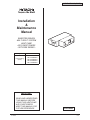
IN-THE-CEILING (DUCT)
Installation
&
Maintenance
Manual
INVERTER-DRIVEN
MULTI-SPLIT SYSTEM
HEAT PUMP
AIR CONDITIONERS
- SET-FREE SERIES -
P5414985
IMPORTANT:
READ AND UNDERSTAND
THIS MANUAL BEFORE
USING THIS HEAT-PUMP
AIR CONDITIONERS.
KEEP THIS MANUAL FOR
FUTURE REFERENCE.
Type Model
In-the-Ceiling
(Duct)
RPI-3.0FSN2SQ
RPI-4.0FSN2SQ
RPI-5.0FSN2SQ
RPI-6.0FSN2SQ
RPI-7.0FSN2SQ

2-4
TC-12001
IN-THE-CEILING (DUCT)
P5414985
i
IMPORTANT NOTICE
Temperature
(
o
C)
Maximum Minimum
Cooling
Operation
Indoor 32 DB/23 WB 21 DB/15 WB
Outdoor 46 DB * -5 DB *
Heating
Operation
Indoor 27 DB 15 DB
Outdoor 15 WB * -20 WB *
DB: Dry Bulb, WB: Wet Bulb
* The temperature may change depending on the outdoor unit.
O
HITACHI pursues a policy of continuing improvement in design and performance of products.
7KHULJKWLVWKHUHIRUHUHVHUYHGWRYDU\VSHFL¿FDWLRQVZLWKRXWQRWLFH
O
HITACHI cannot anticipate every possible circumstance that might involve a potential hazard.
O
This heat pump air conditioner is designed for standard air conditioning only. Do not use this heat pump
air conditioner for other purpose such as drying clothes, refrigerating foods or for any other cooling or
heating process.
O
'RQRWLQVWDOOWKHXQLWLQWKHIROORZLQJSODFHV,WPD\FDXVHD¿UHGHIRUPDWLRQFRUURVLRQRUIDLOXUH
* 3ODFHVZKHUHRLOLQFOXGLQJPDFKLQHU\RLOPD\EHSUHVHQWLQTXDQWLWLHV
* 3ODFHVZKHUHDORWRIVXO¿GHJDVGULIWVVXFKDVLQDKRWVSULQJ
* 3ODFHVZKHUHLQÀDPPDEOHJDVPD\JHQHUDWHRUÀRZ
* 3ODFHVZKHUHVWURQJVDOW\ZLQGEORZVVXFKDVFRDVWUHJLRQV
* 3ODFHVZLWKDQDWPRVSKHUHRIDFLGLW\RUDONDOLQLW\
O
'RQRWLQVWDOOWKHXQLWLQWKHSODFHZKHUHVLOLFRQJDVGULIWV,IWKHVLOLFRQJDVDWWDFKHVWRWKHVXUIDFHRIKHDW
H[FKDQJHUWKH¿QVXUIDFHUHSHOVZDWHU$VDUHVXOWGUDLQZDWHUVSODVKHVRXWVLGHRIWKHGUDLQSDQDQG
VSODVKHGZDWHUUXQVLQVLGHRIHOHFWULFDOER[,QWKHHQGZDWHUOHDNDJHRUHOHFWULFDOGHYLFHVIDLOXUHPD\
occur.
O
3D\DWWHQWLRQWRWKHIROORZLQJSRLQWVZKHQWKHXQLWLVLQVWDOOHGLQDKRVSLWDORURWKHUIDFLOLWLHVZKHUHDQ
HOHFWURPDJQHWLFZDYHJHQHUDWHVIURPDPHGLFDOHTXLSPHQW
* 'RQRWLQVWDOOWKHXQLWLQWKHSODFHZKHUHDQHOHFWURPDJQHWLFZDYHLVGLUHFWO\UDGLDWHGWRWKHHOHFWULFDOER[
UHPRWHFRQWUROFDEOHRUUHPRWHFRQWUROVZLWFK
* ,QVWDOOWKHXQLWDWOHDVWPHWHUVDZD\IURPDQHOHFWURPDJQHWLFZDYHVXFKDVDUDGLR
O
'RQRWLQVWDOOWKHXQLWLQWKHSODFHZKHUHWKHEUHH]HGLUHFWO\FDWFKHVDQLPDOVDQGSODQWV,WFRXOGDGYHUVHO\
affect animals and plants.
O
7KHLQVWDOOHUDQGV\VWHPVSHFLDOLVWVKDOOVHFXUHVDIHW\DJDLQVWWKHUHIULJHUDQWOHDNDJHDFFRUGLQJWRORFDO
UHJXODWLRQVRUVWDQGDUGV7KHIROORZLQJVWDQGDUGVPD\EHDSSOLFDEOHLIORFDOUHJXODWLRQVDUHQRWDYDLODEOH
International Organization for Standardization, ISO5149 or European Standard, EN378 or Japan Standard,
KHKS0010.
O
1RSDUWRIWKLVPDQXDOPD\EHUHSURGXFHGZLWKRXWZULWWHQSHUPLVVLRQ
O
,WLVDVVXPHGWKDWWKLVKHDWSXPSDLUFRQGLWLRQHUZLOOEHRSHUDWHGDQGVHUYLFHGE\(QJOLVKVSHDNLQJSHRSOH
If this is not the case, the customer should be add safety, caution and operating signs in the native
language.
O
,I\RXKDYHDQ\TXHVWLRQVFRQWDFW\RXUGLVWULEXWRURUGHDOHURI+,7$&+,
O
7KLVPDQXDOJLYHVDFRPPRQGHVFULSWLRQDQGLQIRUPDWLRQIRUWKLVKHDWSXPSDLUFRQGLWLRQHUZKLFK\RX
RSHUDWHDVZHOOIRURWKHUPRGHOV
O
7KLVKHDWSXPSDLUFRQGLWLRQHUKDVEHHQGHVLJQHGIRUWKHIROORZLQJWHPSHUDWXUHV2SHUDWHWKHKHDWSXPS
DLUFRQGLWLRQHUZLWKLQWKLVUDQJH
7KLVPDQXDOVKRXOGEHFRQVLGHUHGDVDSHUPDQHQWSDUWRIWKHDLUFRQGLWLRQLQJHTXLSPHQWDQGVKRXOG
UHPDLQZLWKWKHDLUFRQGLWLRQLQJHTXLSPHQW

TC-12001
2-5
IN-THE-CEILING (DUCT)
ii
P5414985
CHECKING PRODUCT RECEIVED
O
Upon receiving this product, inspect it for any shipping damage.
&ODLPVIRUGDPDJHHLWKHUDSSDUHQWRUFRQFHDOHGVKRXOGEH¿OHGLPPHGLDWHO\ZLWKWKHVKLSSLQJFRPSDQ\.
O
&KHFNWKHPRGHOQXPEHUHOHFWULFDOFKDUDFWHULVWLFVSRZHUVXSSO\YROWDJHDQGIUHTXHQF\DQGDFFHVVRULHV
to determine if they are correct.
The standard utilization of the unit shall be explained in these instructions.
Therefore, the utilization of the unit other than those indicated in these instructions is not recommended.
Please contact your local agent, as the occasion arises.
+,7$&+,¶VOLDELOLW\VKDOOQRWFRYHUGHIHFWVDULVLQJIURPWKHDOWHUDWLRQSHUIRUPHGE\DFXVWRPHUZLWKRXW
+,7$&+,¶VFRQVHQWLQDZULWWHQIRUP
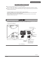
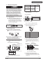
8VHVKLHOGHGZLUHVRIRSHUDWLRQOLQHEHWZHHQWKHLQGRRUDQGWKHRXWGRRUXQLW$QGFRQQHFWWKHVKLHOGHG
SDUWWRWKHHDUWKVFUHZLQWKHHOHFWULFDOER[RIWKHLQGRRUXQLWDVVKRZQLQWKH)LJ
)LJ(DUWK:LULQJ
([DPSOH53,)6164!
Remote Control
Cable
(Shielded Twist
Pair Cable)
Operating Line
(Shielded Twist
Pair Cable)
Power Source Line
to Remote Control Switch
(PC-ARF)
When installing PC-ARF
remote control switch,
connect the both ends
of shield tube to earth.
L
N
Earth
Terminal
Protect the earth wire
to contact with the live part.

2-6
TC-12001
IN-THE-CEILING (DUCT)
P5414985
iii
TABLE OF CONTENTS
1. Safety Summary .............................................................................................................................................1
2. Structure..........................................................................................................................................................
5
2.1 Name of Parts ........................................................................................................................................
5
2.2 Necessary Tools and Instrument List for Installation ..............................................................................
7
3. Transportation and Handling...........................................................................................................................
7
3.1 Transportation ........................................................................................................................................
7
3.2 Handling of Indoor Unit...........................................................................................................................
7
4. Indoor Unit Installation ....................................................................................................................................
7
4.1 Factory-Supplied Accessories ................................................................................................................
7
4.2 Initial Check............................................................................................................................................
9
4.3 Installation ............................................................................................................................................
10
4.3.1 Mounting on Truss ......................................................................................................................
10
4.3.2 Separating Indoor Unit (If Required) (Only for 3.0 - 6.0HP Models)...........................................
10
4.3.3 Mounting on Suspension Brackets (Field-Supplied)...................................................................
11
4.3.4 Adjusting of Unit Level................................................................................................................
11
4.3.5 Connecting Supply Duct .............................................................................................................
12
4.3.6 Setting of External Static Pressure.............................................................................................
12
5. Refrigerant Piping Work................................................................................................................................
13
5.1 Piping Materials....................................................................................................................................
13
5.2 Piping Connection ................................................................................................................................
13
6. Drain Piping ..................................................................................................................................................
14
7. Electrical Wiring ............................................................................................................................................
15
7.1 General Check .....................................................................................................................................
15
7.2 Electrical Wiring Connection ................................................................................................................
15
7.3 Field Minimum Wire Sizes for Power Source .......................................................................................
18
7.4 Setting of Dip Switches ........................................................................................................................
19
7.5 Setting of External Static Pressure.......................................................................................................
20
8. Test Run........................................................................................................................................................
20
9. Safety and Control Device Setting ................................................................................................................
20

TC-12001
2-7
IN-THE-CEILING (DUCT)
P5414985
1
< Signal Words >
O
Signal words are used to identify levels of hazard seriousness.
'H¿QLWLRQVIRULGHQWLI\LQJKD]DUGOHYHOVDUHSURYLGHGEHORZZLWKWKHLUUHVSHFWLYHVLJQDOZRUGV
: '$1*(5LQGLFDWHVDKD]DUGRXVVLWXDWLRQZKLFKLIQRWDYRLGHG
will result in death or serious injury.
: :$51,1*LQGLFDWHVDKD]DUGRXVVLWXDWLRQZKLFKLIQRWDYRLGHG
FRXOGUHVXOWLQGHDWKRUVHULRXVLQMXU\
: &$87,21XVHGZLWKWKHVDIHW\DOHUWV\PEROLQGLFDWHVDKD]DUGRXVVLWXDWLRQZKLFK
LIQRWDYRLGHGFRXOGUHVXOWLQPLQRURUPRGHUDWHLQMXU\
: 127,&(LVXVHGWRDGGUHVVSUDFWLFHVQRWUHODWHGWRSHUVRQDOLQMXU\
: 127(LVXVHIXOLQIRUPDWLRQIRURSHUDWLRQDQGRUPDLQWHQDQFH
1. Safety Summary
DANGER
WARNING
CAUTION
NOTICE
NOTE

2-8
TC-12001
IN-THE-CEILING (DUCT)
2
P5414985
O
Do not perform the installation work, refrigerant piping work, drain pump, drain piping and electrical wiring
connection without referring to our installation manual. If the instructions are not followed, it may result in
DZDWHUOHDNDJHHOHFWULFVKRFNRUD¿UH
O
8VHWKHVSHFL¿HGQRQÀDPPDEOHUHIULJHUDQW5$WRWKHRXWGRRUXQLWLQWKHUHIULJHUDQWF\FOH
'RQRWFKDUJHPDWHULDORWKHUWKDQ5$LQWRWKHXQLWVXFKDVK\GURFDUERQUHIULJHUDQWVSURSDQHRUHWF
R[\JHQÀDPPDEOHJDVHVDFHW\OHQHRUHWFRUSRLVRQRXVJDVHVZKHQLQVWDOOLQJPDLQWDLQLQJDQGPRYLQJ
7KHVHÀDPPDEOHVDUHH[WUHPHO\GDQJHURXVDQGPD\FDXVHDQH[SORVLRQD¿UHDQGLQMXU\.
O
Do not pour water into the indoor unit or outdoor unit. These products are equipped with electrical parts.
If poured, it will cause a serious electrical shock.
O
'RQRWRSHQWKHVHUYLFHFRYHURUDFFHVVSDQHOIRUWKHLQGRRURURXWGRRUXQLWZLWKRXWWXUQLQJ2))WKHPDLQ
power supply.
O
'RQRWWRXFKRUDGMXVWVDIHW\GHYLFHVLQVLGHWKHLQGRRUXQLWRURXWGRRUXQLW,IWKHVHGHYLFHVDUHWRXFKHG
RUUHDGMXVWHGLWPD\FDXVHDVHULRXVDFFLGHQW
O
5HIULJHUDQWOHDNDJHFDQFDXVHGLI¿FXOW\ZLWKEUHDWKLQJGXHWRLQVXI¿FLHQWDLU7XUQ2))WKHPDLQVZLWFK
H[WLQJXLVKDQ\QDNHGÀDPHVDQGFRQWDFW\RXUVHUYLFHFRQWUDFWRULIUHIULJHUDQWOHDNDJHRFFXUV
O
0DNHVXUHWKDWWKHUHIULJHUDQWOHDNDJHWHVWVKRXOGEHSHUIRUPHG
5HIULJHUDQW)OXRURFDUERQIRUWKLVXQLWLVQRQÀDPPDEOHQRQWR[LFDQGRGRUOHVV
+RZHYHULIWKHUHIULJHUDQWLVOHDNHGDQGLVFRQWDFWHGZLWK¿UHWR[LFJDVZLOOJHQHUDWH
$OVREHFDXVHWKHÀXRURFDUERQLVKHDYLHUWKDQDLUWKHÀRRUVXUIDFHZLOOEH¿OOHGZLWKLWZKLFKFRXOGFDXVH
suffocation.
O
The installer and system specialist shall secure safety against refrigerant leakage according to local
regulations or standards.
O
8VHDQ(/%(DUWK/HDNDJH%UHDNHU
,QWKHHYHQWRIIDXOWWKHUHLVGDQJHURIDQHOHFWULFVKRFNRUD¿UHLILWLVQRWXVHG
O
'RQRWLQVWDOOWKHRXWGRRUXQLWZKHUHWKHUHLVKLJKOHYHORIRLOPLVWÀDPPDEOHJDVHVVDOW\DLURUKDUPIXO
gases such as sulfur.
O
)RULQVWDOODWLRQ¿UPO\FRQQHFWWKHUHIULJHUDQWSLSHEHIRUHWKHFRPSUHVVRUVWDUWVRSHUDWLQJ
)RUPDLQWHQDQFHUHORFDWLRQDQGGLVSRVDOUHPRYHWKHUHIULJHUDQWSLSHDIWHUWKHFRPSUHVVRUVWRSV
O
'RQRWSHUIRUPDVKRUWFLUFXLWRIWKHSURWHFWLRQGHYLFHVXFKDVWKHSUHVVXUHVZLWFKZKHQRSHUDWLQJ
,WPD\FDXVHD¿UHDQGH[SORVLRQ
DANGER

TC-12001
2-9
IN-THE-CEILING (DUCT)
P5414985
3
O
'RQRWXVHDQ\VSUD\VVXFKDVDQLQVHFWLFLGHODFTXHUKDLUVSUD\RURWKHUÀDPPDEOHJDVHVZLWKLQ
DSSUR[LPDWHO\RQHPHWHUIURPWKHV\VWHP
O
,IWKHFLUFXLWEUHDNHURUIXVHLVRIWHQDFWLYDWHGVWRSWKHV\VWHPDQGFRQWDFW\RXUVHUYLFHFRQWUDFWRU
O
&KHFNWKDWWKHJURXQGZLUHLVVHFXUHO\FRQQHFWHG,IWKHXQLWLVQRWFRUUHFWO\JURXQGHGLWOHDGHOHFWULF
VKRFN'RQRWFRQQHFWWKHJURXQGZLULQJWRDJDVSLSLQJZDWHUSLSLQJOLJKWLQJFRQGXFWRURUJURXQGZLULQJ
IRUWHOHSKRQH
O
&RQQHFWDIXVHRIVSHFL¿HGFDSDFLW\
O
%HIRUHSHUIRUPLQJDQ\EUD]LQJZRUNFKHFNWRHQVXUHWKDWWKHUHLVQRÀDPPDEOHPDWHULDODURXQG
:KHQXVLQJWKHUHIULJHUDQWEHVXUHWRZHDUOHDWKHUJORYHVWRSUHYHQWFROGLQMXULHV
O
3URWHFWWKHZLUHVHOHFWULFDOSDUWVHWFIURPUDWVRURWKHUVPDOODQLPDOV
,IQRWSURWHFWHGUDWVPD\JQDZDWXQSURWHFWHGSDUWVDQGZKLFKPD\OHDGWRD¿UH
O
)L[WKHFDEOHVVHFXUHO\([WHUQDOIRUFHVRQWKHWHUPLQDOVFRXOGOHDGWRD¿UH
O
3URYLGHDVXI¿FLHQWO\VWURQJIRXQGDWLRQ,IQRWWKHXQLWPD\IDOOGRZQDQGLWPD\OHDGWRLQMXULHV
O
'RQRWLQVWDOOWKHXQLWLQDSODFHZKHUHRLOYDSRURUJDQLFVROYHQWDQGFRUURVLYHJDVDPPRQLDVXOIXU
FRPSRXQGDQGDFLGPD\EHSUHVHQWLQTXDQWLWLHV
,WPD\FDXVHUHIULJHUDQWOHDNDJHGXHWRFRUURVLRQHOHFWULFDOVKRFNGHWHULRUDWHGSHUIRUPDQFHDQG
EUHDNDJH
O
3HUIRUPWKHHOHFWULFDOZRUNDFFRUGLQJWR,QVWDOODWLRQ0DQXDODQGDOOWKHUHOHYDQWUHJXODWLRQDQGVWDQGDUGV
,IWKHLQVWUXFWLRQVDUHQRWIROORZHGDQHOHFWULFDOVKRFNDQG¿UHPD\RFFXUGXHWRLQVXI¿FLHQWFDSDFLW\DQG
LQDGHTXDWHSHUIRUPDQFH
O
8VHVSHFL¿HGFDEOHVEHWZHHQXQLWVDQGFKRRVHWKHFDEOHVFRUUHFWO\
,IQRWDQHOHFWULFDOVKRFNRU¿UHPD\RFFXU
O
(QVXUHWKDWWKHZLULQJWHUPLQDOVDUHWLJKWHQHGVHFXUHO\ZLWKWKHVSHFL¿HGWRUTXHV
,IQRWJHQHUDWLQJ¿UHRUDQHOHFWULFVKRFNDWWKHWHUPLQDOFRQQHFWLRQSDUWPD\RFFXU
CAUTION
O
'RQRWVWHSRUSXWDQ\PDWHULDORQWKHSURGXFW
O
'RQRWSXWDQ\IRUHLJQPDWHULDORQWKHXQLWRULQVLGHWKHXQLW
O
3URYLGHDVWURQJDQGFRUUHFWIRXQGDWLRQVRWKDW
D7KHRXWGRRUXQLWLVQRWRQDQLQFOLQH
E$EQRUPDOVRXQGGRVHQRWRFFXU
F7KHRXWGRRUXQLWZLOOQRWIDOOGRZQGXHWRDVWURQJZLQGRUHDUWKTXDNH
WARNING

2-10
TC-12001
IN-THE-CEILING (DUCT)
4
P5414985
NOTICE
O
Do not install the indoor unit, outdoor unit, remote control switch and cable within approximately 3 meters
from strong electromagnetic wave radiators such as medical equipments.
O
Supply electrical power to the system to energize the oil heater for 12 hours before startup after a long
shutdown.
O
Make sure that the outdoor unit is not covered with snow or ice, before operation.
O
In some cases, the packaged air conditioner may not be operated normally under the following cases.
* In case that electrical power for the packaged air conditioner is supplied from the same power
transformer as the device*.
* In case that the power source wires for the device* and the packaged air conditioner are located close to
each other.
Device*: (Ex) /LIWFRQWDLQHUFUDQHUHFWL¿HUIRUHOHFWULFUDLOZD\LQYHUWHUSRZHUGHYLFHDUFIXUQDFH
electric furnace, large-sized induction motor and large-sized switch.
It consumes a large quantity of electrical power.
Regarding the cases mentioned above, surge voltage may be inducted in the power supply wiring for the
packaged air conditioner due to a rapid change in power consumption of the device and an activation of
switch.
7KHUHIRUHFKHFNWKH¿HOGUHJXODWLRQVDQGVWDQGDUGVEHIRUHSHUIRUPLQJHOHFWULFDOZRUNLQRUGHUWRSURWHFW
the power supply for the packaged air conditioner.
NOTE
O
It is recommended that the room will be ventilated every 3 to 4 hours.
O
The heating capacity of the heat pump unit is decreased according to the outdoor air temperature.
7KHUHIRUHLWLVUHFRPPHQGHGWKDWDX[LOLDU\KHDWLQJHTXLSPHQWEHXVHGLQWKH¿HOGZKHQWKHXQLWVLV
installed in a low temperature region.

TC-12001
2-11
IN-THE-CEILING (DUCT)
P5414985
5
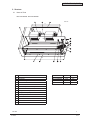
2. Structure
2.1 Name of Parts
< RPI-3.0FSN2SQ - RPI-6.0FSN2SQ >
No. Part Name
1 Fan
2 Fan Motor
3 Heat Exchanger
4 Distributor
5 Strainer
6 Micro-Computer Control Expansion Valve
7 Electrical Control Box
8 Refrigerant Gas Pipe Connection
9 Refrigerant Liquid Pipe Connection
10 Drain Pipe Connection
11 Float Switch
12 Drain Pan
13 Air Outlet
14 Air Inlet
Model L1 L2
RPI-3.0FSN2SQ 1,076 879
RPI-4.0FSN2SQ 1,076 879
RPI-5.0FSN2SQ 1,300 1,000
RPI-6.0FSN2SQ 1,300 1,000
350
800
(303)
497
L2
Unit: mm
L1

2-12
TC-12001
IN-THE-CEILING (DUCT)
6
P5414985
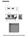
< RPI-7.0FSN2SQ >
No. Part Name
1 Fan
2 Fan Motor
3 Heat Exchanger
4 Distributor
5 Micro-Computer Control Expansion Valve
6 Strainer
7 Electrical Control Box
8 Refrigerant Gas Pipe Connection
9 Refrigerant Liquid Pipe Connection
10 Drain Pipe Connection
11 Float Switch
12 Drain Pan
13 Air Outlet
14 Air Inlet
‚c‚`‚m‚f‚d‚q
‚c‚`‚m‚f‚d‚q
‚t‚r‚d @‚o‚b |‚o ‚P ‚g
‚g ‚h ‚s‚`‚b‚g ‚h @‚` ‚h‚q
@
@
‚b‚n‚m‚c ‚h‚s ‚h‚n‚m‚d‚q
9
8
10
11
13
4531412
6
71
7
721430 440
550

TC-12001
2-13
IN-THE-CEILING (DUCT)
P5414985
7
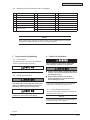
2.2 Necessary Tools and Instrument List for Installation
NOTE
About vacuum pump, gas hose, charging cylinder, gauge manifold, please use suitable
equipments for R410A respectively. Do not mix other refrigerant.
4. Indoor Unit Installation
4.1 Factory-Supplied Accessories
Check to ensure that the following accessories are
packed with the indoor unit.
NOTE
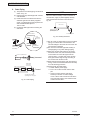
3. Transportation and Handling
3.1 Transportation
Transport the product as close to the installation
location as practical before unpacking.
3.2 Handling of Indoor Unit
If any of these accessories are not packed with the
unit, please contact your contractor.
Do not put any foreign material into the indoor
unit and check to ensure that none exists in the
indoor unit before the installation and test run.
2WKHUZLVHD¿UHRUIDLOXUHHWFPD\RFFXU
Be careful not to damage on insulation
materials of unit’s surface when lifting.
Do not put any material on the product.
It is recommended that indoor units be installed
KLJKHUWKDQPHWHUVIURPWKHÀRRUOHYHO
O
Check to ensure that the ceiling slab is strong
enough. If not strong enough, the indoor unit
may fall down on you.
O
Do not install the indoor unit outdoors.
If installed outdoors, an electric hazard or
electric leakage will occur.
'RQRWLQVWDOOWKHLQGRRUXQLWLQDÀDPPDEOH
HQYLURQPHQWWRDYRLG¿UHRUDQH[SORVLRQ
No. Tool No. Tool No. Tool
1 Handsaw 8 Plier 16 Cutter for Wires
2 Phillips Screwdriver 9 Pipe Cutter 17 Gas Leak Detector
3 Vacuum Pump 10 Brazing Kit 18 Leveller
4 Refrigerant Gas Hose 11 Hexagon Wrench 19 Clamper for Solderless Terminals
5 Megohmmeter 12 Spanner 20 Hoist (for Indoor Unit)
6 Copper Pipe Bender 13 Weigher 21 Ammeter
7
Manual Water Pump
(for Indoor Unit)
14 Charging Cylinder 22 Voltage Meter
15 Gauge Manifold 23 Wrench

2-14
TC-12001
IN-THE-CEILING (DUCT)
8
P5414985
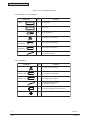
Table 4.1 Factory-Supplied Accessories
Accessory Purpose
Flange
Flange
Screw
Hose Clamp
Insulation
(22 IDx130)
Insulation
(40 IDx130)
Cord Clamp
Q'ty
1
1
16
1
1
1
10
For Air Outlet
For Air Inlet
For Fixing Flanges
For Drain Hose Connection
For Refrigerant Liquid Piping
For Refrigerant Gas Piping
For Fixing Thermal Insulation
for Refrigerant Pipings
Accessory Purpose
Hose Clamp
Insulation
(28 ID 130)
Insulation
(40 ID 130)
Cord Clamp
Q'ty
1
1
1
10
For Drain Hose Connection
For Refrigerant Liquid Piping
For Refrigerant Gas Piping
For Fixing Thermal Insulation
for Refrigerant Pipings
Bolt
26 For Connecting Pipeline with Indoor Unit
Ring Core
1
< RPI-3.0FSN2SQ - RPI-6.0FSN2SQ >
< RPI-7.0FSN2SQ >

TC-12001
2-15
IN-THE-CEILING (DUCT)
P5414985
9
(Total Refrigerant Quantity per one Outdoor Unit)
Volume of the room where this
Indoor Unit is installed.
()
0.3kg/m
3
O
Check to ensure that the number of below
is within 0.3kg/m
3
. Otherwise it may cause
danger situation if the refrigerant in the
Outdoor Unit leaks into the room where this
Indoor Unit is installed.
In detail, refer to the Installation Manual for
outdoor unit.
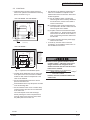
4.2 Initial Check
x
Install the indoor unit with a proper clearance
around it for operation and maintenance working
space, as shown in Fig. 4.1.
x
Pay attention to the following points when the
indoor unit is installed in a hospital or other
facilities where there are electronic waves from
medical equipment.
(A) Do not install the indoor unit where the
electromagnetic wave is directly radiated to
the electrical box, remote control cable or
remote control switch.
(B) Install the indoor unit and components as
far as practical or at least 3 meters from the
electromagnetic wave radiator.
(C) Prepare a steel box and install the remote
control switch in it. Prepare a steel conduit
tube and wire the remote control cable in it.
Then, connect the ground wire with the box
and the tube.
(D) ,QVWDOODQRLVH¿OWHUZKHQWKHSRZHUVXSSO\
emits harmful noises.
x
To avoid any corrosive action to the heat
exchangers, do not install the indoor unit in an
acid or alkaline environment.
Fig. 4.1 Operation and Installation Space
x
Consider the air distribution from the indoor unit
to the space of the room, and select a suitable
location so that uniform air temperature in the
room can be obtained.
x
'RQRWLQVWDOOÀDPPDEOHSDUWVLQWKHVHUYLFH
space for the indoor unit.
x
Avoid obstacles which may hamper the air intake
RUWKHDLUGLVFKDUJHÀRZ
x
Do not install the indoor unit in a machine shop
RUNLWFKHQZKHUHYDSRUIURPRLORULWVPLVWÀRZV
to the indoor unit.
The oil will deposit on the heat exchanger,
thereby reducing the indoor unit performance,
and may deform and in the worst case, break
the plastic parts of the indoor unit.
< RPI-3.0FSN2SQ - RPI-6.0FSN2SQ >
< RPI-7.0FSN2SQ >
Min. 600Min. 600 5 and 6HP 1300
3 and 4HP 1076
5 and 6HP 1000
3 and 4HP 879
497
303
(75)
Min. 1000Min. 1000 800
30
30
Electrical
Control Box
Service Access Door
(Min. 450x450)
In case that
the ceiling
board can not
be detected
for servicing,
prepare a
service access
door below the
indoor unit for
removing the
indoor unit.
View from Top
In case that
the ceiling
board can not
be detected
for servicing,
prepare a
service access
door below the
indoor unit for
removing the
indoor unit.
Min. 600Min. 600 1,430
1,288
830
(75)
Min. 1,000Min. 1,000 550 3030
Service Access Door
(Min. 450x450)
Air Outlet
Air Inlet
Separate Pipeline
(Field-supplied)
500
100
100
Service
Space
Electrical
Control Box
View from Top

2-16
TC-12001
IN-THE-CEILING (DUCT)
10
P5414985
(2) Apply an auxiliary drain under the indoor unit
if the ambient humidity is higher than 80%
(RH).
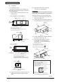
4.3 Installation
4.3.1 Mounting on Truss
In the case that the indoor unit is installed in the
false ceiling space without hanging, pay attention
to the following items.
(1) Apply vibration absorbing mats (10t) under
the indoor unit.
< RPI-3.0FSN2SQ - RPI-6.0FSN2SQ >
< RPI-7.0FSN2SQ >
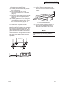
(3) If further disassembly is required, unplug the
fan motor connector (Fig. 4.3).
(4) Remove the 5 bolts (M6) securing the
fan assembly to the heat exchanger
compartment. The fan assembly will be
lifted off (Fig. 4.3).
Fig. 4.3 Removing Fan Assembly
4.3.2 Separating Indoor Unit (If Required)
(Only for 3.0 - 6.0HP Models)
ATTENTION:
Separate the indoor unit only when necessary.
'LVDVVHPEOHDQGUHDVVHPEOHRQDÀDWVXUIDFH
x
Separate the indoor unit in the following order.
(1) Remove the 4 bolts (M6) on the back of the
supply air box (Fig. 4.2).
(2) Carefully pull the fan cover away, taking care
not to damage the fan motor wiring (Fig. 4.2).
Fig. 4.2
P
P
Wooden Bar
Wooden Bar
Truss
Truss
Field-Supplied Vibration Absorbing
Mat (10t)
Vibration Absorbing
Mat (10t)
View from
Place the three wooden bars on the
truss as showing in the figure.
Note that the middle wooden bar should
be placed in the center position of the unit.
Vibration Absorbing
Mat (10t)
Vibration Absorbing
Mat (10t)
Wooden Bar Truss
Wooden Bar
Truss
Indoor Unit
Place the three wooden bars on the
truss as showing in the figure.
Note that the middle wooden bar should be placed
in the center position of the unit.
P
View from P
Electrical Box
Fan Cover
Supply Air
Return Air
Heat Exchanger
Compartment
Fan Assembly
Heat Exchanger
Compartment
Thermistor
for Air Inlet Temp.
Connector
for Fan Motor
When removing the fan assembly, loosen the
screws and lift off the fan assembly.
When attaching the fan assembly,
mount it onto the screws as shown.
NOTES:
1) The fan cover has sharp edges. Take care not to
injure yourself when handling.
2) Ensure not to damage or deform the air inlet
temperature thermistor.
3) Check to ensure that the connector for the fan motor is
connected to the unit.
4) Attach the fan cover as shown in the figure.
5) Tighten the screws securely.
If they are loose, vibration or noise will occur.
Fan Assembly
Fan Support
Fan Cover
Electrical Box

TC-12001
2-17
IN-THE-CEILING (DUCT)
P5414985
11
x
Rejoin the return air and supply air
compartments in the following order.
(5) Carefully place the fan assembly back into
the original position.
(6) Fix the fan assembly onto the heat
exchanger compartment with 4 bolts (M6)
(Fig. 4.3).
(7) Re-connect the fan motor connector into the
plug on the heat exchanger compartment
(Fig. 4.3).
(8) Carefully replace the fan cover, taking care
QRWWRGDPDJHWKHIDQPRWRUZLULQJDQG¿[
the cover with the 4 bolts (M6) (Fig. 4.2).
4.3.3 Mounting on Suspension Brackets
(Field-Supplied)
Mount the suspension brackets to the suspension
bolts and secure them with nuts as shown. Use
¿HOGVXSSOLHGDQJOHDQGWKUHDGHGURGV0RU
greater are also recommended to brace the unit
mounting. (Check with local and national building
codes and or a structural engineer as to the
¿[LQJRIWKHXQLWRUEXLOGLQJVXSSRUWVWUXFWXUHLI
applicable.)
4.3.4 Adjusting of Unit Level
&KHFNWRHQVXUHWKDWWKHIRXQGDWLRQLVÀDW
taking into account the maximum foundation
gradient.
NOTE
Fig. 4.4 Foundation Gradient
(2) The unit should be installed so that the rear
VLGHRIWKHXQLWLVVOLJKWO\PPWRPP
lower than the front side, in order to avoid
the incorrect position of the drain discharge.
Keep the unit as well as relevant equipment
covered with the vinyl cover during installation
work.
Suspension Bracket
Nut
Threaded Rod
Washer
5mm

2-18
TC-12001
IN-THE-CEILING (DUCT)
12
P5414985
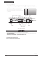
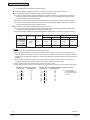
4.3.5 Connecting Supply Duct
(1) The supply duct should be connected with the indoor unit through canvas ducts, in order to avoid
DEQRUPDOVRXQGYLEUDWLRQ5HIHUWR)LJ7KHXQLWLVHTXLSSHGZLWKDSUHGULOOHGGXFWÀDQJHIRUWKH
supply duct connection.
(2) Attach the vibration proof rubber to Sling Bolt in order to avoid abnormal sound vibration.
(3) Undamped natural frequency is shown in the table.
(4) 'XFWPDWHULDOVKRXOGEHQRQÀDPPDEOHPDWHULDO
(5) Perform the heat insulation work over the duct for dew
protection.
O
,IDORZHUVRXQGOHYHOLVIXUWKHUUHTXLUHGLQVWDOOVLOHQFHU¿HOGVXSSOLHG
O
Design duct arrangement as “Unit External Static Pressure=Pressure Drop of Duct+Pressure Drop
of Air Outlet and Air Inlet”.
If duct design is not appropriate, big sound and splash will occur.
HP Undamped Natural Frequency
3.0 12 to 23 Hz
4.0 11 to 22 Hz
5.0 11 to 23 Hz
6.0 11 to 23 Hz
7.0 12 to 20 Hz
4.3.6 Setting of External Static Pressure
Refer to 7.5 “Setting of External Static Pressure”.
Fig. 4.5 Duct Connection
Truss
Vibration
Absorbing
Mat (10t)
Wooden Bar
Service Access Panel
(450mm x 450mm)
Keep Horizontal
Air Outlet Air Inlet
Damper for
Adjusting Air Volume
Damper for
Adjusting Air Volume
Silencer Canvas Duct SilencerCanvas Duct
Outdoor Air
(with Air Filter)
Thermal
Insulation
Indoor Unit

TC-12001
2-19
IN-THE-CEILING (DUCT)
P5414985
13
5. Refrigerant Piping Work
Fig. 5.1 Position of Piping Connection
(1) Position of piping connection is shown
below.
O
Cap the end of the pipe when the pipe is to be
inserted through a hole.
O
Do not put pipes on the ground directly
without a cap or vinyl tape at the end of the
pipe.
O
An excess or a shortage of refrigerant is the
main cause of trouble to the units.
Charge the correct refrigerant quantity.
5.1 Piping Materials
(1) Prepare locally-supplied copper pipes.
(2) Select clean copper tubes making sure there
is no dust and moisture inside the tubes.
Before connecting pipes, blow the inside of
the tubes with nitrogen or dry air, to remove
any dust or foreign materials.
5.2 Piping Connection
(2) :KHQWLJKWHQLQJWKHÀDUHQXWXVHWZR
spanners as shown in Fig. 5.3.
Model a
RPI-3.0FSN2SQ 71
RPI-4.0FSN2SQ
RPI-5.0FSN2SQ
RPI-6.0FSN2SQ
81
mm (in.)
Model Gas Piping Liquid Piping
RPI-3.0FSN2SQ
RPI-4.0FSN2SQ
RPI-5.0FSN2SQ
I
15.88 (5/8)
I
9.52 (3/8)
RPI-6.0FSN2SQ
I
15.88 (5/8)
or
I
19.05 (3/4)*
*: When the pipe size of
I
19.05 is used, apply the
UHGXFHU¿HOGVXSSOLHGWR¿WWKH
I
15.88 pipe for
indoor unit connection.
< RPI-3.0FSN2SQ - RPI-6.0FSN2SQ >
< RPI-7.0FSN2SQ >
Fig. 5.2 Position of Piping Connection
Fig. 5.4 Insulation on Pipes
Fig. 5.3 Tightening Work of Flare Nut
(4) Evacuation and refrigerant charging
procedures should be performed according
to “Installation & Maintenance Manual” of the
outdoor unit.
(3) After connecting the refrigerant piping, seal
the refrigerant pipes by using the factory-
supplied insulation material as shown in Fig
5.4.
Pipe Size Tightening Torque (N-m)
I
6.35mm 20
I
9.52mm 40
I
15.88mm 80
I
19.05mm 100
8VHWKHVSHFL¿HGQRQÀDPPDEOHUHIULJHUDQW
(R410A) to the outdoor unit in the refrigerant
cycle. Do not charge material other than R410A
into the unit such as hydrocarbon refrigerants
SURSDQHRUHWFR[\JHQÀDPPDEOHJDVHV
(acetylene or etc.) or poisonous gases when
installing, maintaining and moving. These
ÀDPPDEOHVDUHH[WUHPHO\GDQJHURXVDQGPD\
FDXVHDQH[SORVLRQD¿UHDQGLQMXU\
Correct Incorrect
Refrigerant Liquid Pipe
Connection
Refrigerant Gas Pipe
Connection
Drain Pipe Connection
377
321
246
244
204
23
90
95
a
Refrigerant Liquid
Pipe Connection
Refrigerant Gas
Pipe Connection
Drain Pipe
Connection
174
550 1,430
440
320
200
25
Air Outlet Air Inlet
90
230
167
Insulation for
Refrigerant Pipe
(Factory-Supplied)
Insulation for
Refrigerant Pipe
(Field-Supplied)
Refrigerant Pipe
(Field-Supplied)
Cord Clamp
(Factory-Supplied)
Unit
Side
Insulation Material
(Factory-Supplied)

2-20
TC-12001
IN-THE-CEILING (DUCT)
14
P5414985
When the relative humidity of inlet or ambient air
H[FHHGVDSSO\DQ¿HOGVXSSOLHGDX[LOLDU\
drain pan beneath the indoor unit as shown in
Fig. 6.2.
Fig. 6.2 Auxiliary Drain Pan
'RQRWFUHDWHDQXSSHUVORSHRUULVHIRUWKHGUDLQ
SLSLQJVLQFHGUDLQZDWHUFDQÀRZEDFNWRWKH
XQLWDQGOHDNDJHWRWKHURRPZLOORFFXUZKHQWKH
unit operation is stopped.
Do not connect the drain pipe with sanitary or
sewage piping or any other drainage piping.
When the common drain piping is connected
with other indoor units, the connected position
of each indoor unit must be higher than the
common piping. The pipe size of the common
drain pipe must be large enough according to
the unit size and number of units.
$IWHUSHUIRUPLQJGUDLQSLSLQJZRUNDQGHOHFWULFDO
ZLULQJFKHFNWRHQVXUHWKDWZDWHUÀRZVVPRRWKO\
as in the following procedure.
&KHFNLQJZLWKWKH)ORDW6ZLWFK
a. 6ZLWFK21WKHSRZHUVXSSO\
b. Pour 2 or 2.5 liters of water into the drain
pan.
c. &KHFNWRHQVXUHWKDWWKHZDWHUÀRZV
VPRRWKO\RUZKHWKHUQRZDWHUOHDNDJH
occurs. When water cannot be found at the
end of the drain piping, pour another 2 liters
of water into the drain.
6. Drain Piping
The position of the drain piping connection is
shown in Fig. 6.1.
Prepare polyvinyl chloride pipe with a 32mm
outer diameter.
Fasten the tube to the drain hose with the
DGKHVLYHDJHQWDQGWKHIDFWRU\VXSSOLHG
clamp. The drain piping must be performed
ZLWKD'2:16/23(SLWFKRI
1/25 to 1/100.
Insulate the drain pipe after connecting the
drain hose.
Fig. 6.1 Drain Piping
NOTE
Indoor Unit
Auxiliary Drain Pan
(Field-Supplied)
To the Atmosphere
1/25 to 1/100
Down-Slope
Thermal Insulation
(Field-Supplied)
Drain Hose
Thermal
Insulation
Clamp
Polyvinyl
Chloride Tube
(Field-Supplied)
Seal
(Adhesive)
Drain Piping
Connection
1/25 to 1/100 Down-Slope
Common Drain Piping
This drain pipe shall be
separating from other pipes.
Incorrect: Upward Slope
Unit
Rising Part
Incorrect
Correct

TC-12001
2-21
IN-THE-CEILING (DUCT)
P5414985
15
7. Electrical Wiring
O
Wrap the accessory packing around the
wires, and plug the wiring connection hole
with the seal material to protect the product
from any condensate water or insects.
O
Tightly secure the wires with the cord clamp
inside the indoor unit.
O
Secure the cable of the remote control switch
using the cord clamp inside the electrical
box.
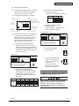
7.1 General Check
(1) 0DNHVXUHWKDWWKH¿HOGVHOHFWHGHOHFWULFDO
FRPSRQHQWVPDLQSRZHUVZLWFKHVFLUFXLW
EUHDNHUVZLUHVFRQGXLWFRQQHFWRUVDQG
ZLUHWHUPLQDOVKDYHEHHQSURSHUO\VHOHFWHG
DFFRUGLQJWRWKHHOHFWULFDOGDWDJLYHQLQ
³7HFKQLFDO&DWDORJ´0DNHVXUHWKDWWKH
FRPSRQHQWVFRPSO\ZLWK1DWLRQDO(OHFWULFDO
&RGH1(&
(2) &KHFNWRHQVXUHWKDWWKHSRZHUVXSSO\
voltage is within
+RIWKHUDWHGYROWDJH
(3) &KHFNWKHFDSDFLW\RIWKHHOHFWULFDOZLUHV
,IWKHSRZHUVRXUFHFDSDFLW\LVWRRORZWKH
V\VWHPFDQQRWEHVWDUWHGGXHWRWKHYROWDJH
GURS
(4) &KHFNWRHQVXUHWKDWWKHJURXQGZLUHLV
FRQQHFWHG
(5) 3RZHU6RXUFH0DLQ6ZLWFK
,QVWDOODPXOWLSROHPDLQVZLWFKZLWKDVSDFH
RIPPRUPRUHEHWZHHQHDFKSKDVH
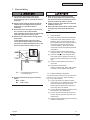
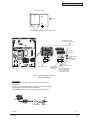
7.2 (OHFWULFDO:LULQJ&RQQHFWLRQ
7KHHOHFWULFDOZLULQJFRQQHFWLRQIRUWKHLQGRRUXQLW
LVVKRZQLQ)LJIRU+3PRGHOVRU
)LJIRU+3PRGHO
(1) &RQQHFWWKHFDEOHRIDQRSWLRQDOUHPRWH
FRQWUROVZLWFKRUDQRSWLRQDOH[WHQVLRQFDEOH
WRWKHFRQQHFWRUVRQWKHSULQWHGFLUFXLW
ERDUGLQVLGHWKHHOHFWULFDOER[WKURXJKWKH
FRQQHFWLQJKROHLQWKHFDELQHW
(2) &RQQHFWWKHSRZHUVXSSO\DQGHDUWKZLUHVWR
WKHWHUPLQDOVLQWKHHOHFWULFDOER[
(3) &RQQHFWWKHZLUHVEHWZHHQWKHLQGRRUXQLW
DQGWKHRXWGRRUXQLWWRWKHWHUPLQDOVLQWKH
HOHFWULFDOER[
(4) 7LJKWO\FODPSWKHZLUHVXVLQJWKHFRUGFODPS
LQVLGHWKHHOHFWULFDOER[
)LJ (OHFWULFDO:LULQJ'LDJUDPRI
7UDQVIRUPHU7)
O
Tighten screws according to the following
torque.
M3.5: 1.2 N-m
M5: 2.0 to 2.4 N-m
O
Turn OFF the main power switch to the
indoor unit and the outdoor unit before
electrical wiring work or a periodical check is
performed.
O
Check to ensure that the indoor fan and the
outdoor fan have stopped before electrical
wiring work or a periodical check is
performed.
O
Protect the wires, drain pipe, electrical parts,
etc. from rats or other small animals.
If not protected, rats may gnaw at unprotected
SDUWVDQGDWWKHZRUVWD¿UHZLOORFFXU
O
Check the item below before turning ON the
main switch.
In case that the power source for indoor
unit is 220V (nominal voltage), change CN27
(connector) to CN28 of transformer (TF) in the
electrical control box as shown in Fig. 7.1.
12V
12V
PCN1
CN1
TF
240V
220V
CN28
CN27
PCB1
Connector
for 240V
Connector
for 220V
12
12

2-22
TC-12001
IN-THE-CEILING (DUCT)
16
P5414985
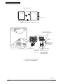
Fig. 7.2 Electrical Wiring Connection
(Only for 3.0 - 6.0HP Models)
Remote Control
Cable
(Shielded Twist
Pair Cable)
Operating Line
(Shielded Twist
Pair Cable)
Power Source Line
to Remote Control Switch
(PC-ARF)
When installing PC-ARF
remote control switch,
connect the both ends
of shield tube to earth.
L
N
Earth
Terminal
Protect the earth wire
to contact with the live part.
Electrical Box Cover
Air Inlet
Remove the fixing screws for Electrical box cover.
La page est en cours de chargement...
La page est en cours de chargement...
La page est en cours de chargement...
La page est en cours de chargement...
-
 1
1
-
 2
2
-
 3
3
-
 4
4
-
 5
5
-
 6
6
-
 7
7
-
 8
8
-
 9
9
-
 10
10
-
 11
11
-
 12
12
-
 13
13
-
 14
14
-
 15
15
-
 16
16
-
 17
17
-
 18
18
-
 19
19
-
 20
20
-
 21
21
-
 22
22
-
 23
23
-
 24
24


Hitachi RPI-5.0FSN2SQ Installation & Maintenance Manual
- Catégorie
- Climatiseurs split-system
- Taper
- Installation & Maintenance Manual
- Ce manuel convient également à
dans d''autres langues
- English: Hitachi RPI-5.0FSN2SQ
Documents connexes
Autres documents
-
 Mitsubishi Electronics MSZ-FD09/12NA Manuel utilisateur
-
Mitsubishi Electric MSZ-GS18NA-U1 GS-Series 18k BTU Wall Mounted Unit Manuel utilisateur
-
Fujitsu AOGG24LAT3 Guide d'installation
-
LG WM3500CW Le manuel du propriétaire
-
Mitsubishi Electric VG79J799H01 Manuel utilisateur
-
York YDOA096B21S Manuel utilisateur
-
Fujitsu ASGA24FUTA-B Guide d'installation
-
Fujitsu ASGA24FUTA-B Guide d'installation
-
-
Toshiba RAS-M05G3KVSG-E Manuel utilisateur
