
52058189 REV 1 © 2019 Greenlee Tools, Inc. 10/19
CMT-90
Clamp-on Meter
Medidor
con pinza
Contrôleur
numérique
à pinces
INSTRUCTION MANUAL
INSTRUCTION MANUAL
MANUAL DE INSTRUCCIONES
MANUEL D’INSTRUCTIONS
Read and understand all of the instructions and safety
information in this manual before operating or servicing
thistool.
Lea y entienda todas las instrucciones y la información
sobre seguridad que aparecen en este manual, antes de
manejar estas herramientas o darles mantenimiento.
Lire attentivement et bien comprendre toutes les
instructions et les informations sur la sécurité de ce manuel
avant d’utiliser ou de procéder à l’entretien de cet outil.
Register this product at www.greenlee.com / Registre este producto
en www.greenlee.com / Enregistrez votre produit en ligne, www.greenlee.com

2
Description
The Greenlee CMT-90 Digital Clamp-on Meter is a hand-held testing device with the
following measurement capabilities: AC and DC voltage, AC current, and resistance.
It also tests diodes and verifies continuity. The CMT-90 is a true RMS-reading meter.
This unit automatically determines measurement function based on input. It has a
smart data hold feature with audible and visual alert if the input changes significantly
while the unit is in HOLD mode. The unit automatically enters HOLD mode when the
jaw is removed from a conductor while measuring AC current. It performs a self-test
and displays approximate remaining battery capacity during the power-up sequence.
The Automatic Power Off feature can be disabled if desired.
The display automatically illuminates for easy viewing in dark areas.
Safety
Safety is essential in the use and maintenance of Greenlee tools and equipment. This
instruction manual and any markings on the tool provide information for avoiding
hazards and unsafe practices related to the use of this tool. Observe all of the safety
information provided.
Purpose of This Manual
This instruction manual is intended to familiarize all personnel with the safe opera-
tion and maintenance procedures for the Greenlee CMT-90 Digital Clamp-on Meter.
Keep this manual available to all personnel.
Replacement manuals are available upon request at no charge
at www.greenlee.com.
KEEP THIS MANUAL
All specifications are nominal and may change as design improvements occur.
Greenlee Tools, Inc. shall not be liable for damages resulting from misapplication or misuse of its
products.
® Registered: The color green for electrical test instruments is a registered trademark of
Greenlee Tools, Inc.
Do not discard this product or throw away!
For recycling information, go to www.greenlee.com.

3
CMT-90
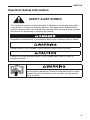
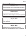
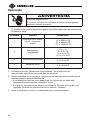
Important Safety Information
SAFETY ALERT SYMBOL
This symbol is used to call your attention to hazards or unsafe practices which
could result in an injury or property damage. The signal word, defined below,
indicates the severity of the hazard. The message after the signal word provides
information for preventing or avoiding the hazard.
Immediate hazards which, if not avoided, WILL result in severe injury or death.
Hazards which, if not avoided, COULD result in severe injury or death.
Hazards or unsafe practices which, if not avoided, MAY result in injury or
property damage.
Read and understand this material before operating or
servicing this equipment. Failure to understand how to safely
operate this tool could result in an accident causing serious
injury or death.

4
Important Safety Information
Electric shock hazard:
Contact with live circuits could result in severe injury or death.
Electric shock and fire hazard:
• Do not expose this unit to rain or moisture.
• Do not use the unit if it is wet or damaged.
• Use test leads or accessories that are appropriate for the application. Refer to
the category and voltage rating of the test lead or accessory.
• Inspect the test leads or accessory before use. They must be clean and dry, and
the insulation must be in good condition.
• Use this unit for the manufacturer’s intended purpose only, as described in this
manual. Any other use can impair the protection provided by the unit.
Failure to observe these warnings could result in severe injury or death.
Electric shock hazard:
• Do not apply more than the rated voltage between any two input terminals, or
between any input terminal and earth ground.
• Do not contact the test lead tips or any uninsulated portion of the accessory.
Failure to observe these warnings could result in severe injury or death.

5
CMT-90
Important Safety Information
Electric shock hazard:
• Do not operate with the case or battery cover open.
• Before removing the case or battery cover, remove the test leads (or jaw) from
the circuit and shut off the unit.
Failure to observe these warnings could result in severe injury or death.
Electric shock hazard:
• Unless measuring voltage or current, shut off and lock out power. Make sure that
all capacitors are discharged. Voltage must not be present.
• Using this unit near equipment that generates electromagnetic interference can
result in unstable or inaccurate readings.
Failure to observe these warnings could result in severe injury or death.
Electric shock hazard:
• Do not attempt to repair this unit. It contains no user-serviceable parts.
• Do not expose the unit to extremes in temperature or high humidity.
Refer to “Specifications.”
• Do not connect to voltage for longer than 30 seconds.
Failure to observe these precautions may result in injury and can damage the unit.
Electric shock hazard:
Do not use the meter to measure voltages in circuits that could be damaged or
actuated by the meter’s low input impedance (approximately 4 kΩ).
Failure to observe this precaution may result in injury and can damage the unit.

6
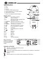
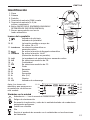
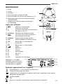
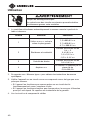
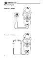
Identification
1. Jaw
2. Lever
3. Display
4. Common (COM) input terminal
5. Volts or resistance (V-Ω) input terminal
6. ON/OFF/HOLD button
7. Sensor for automatic backlit display
Display Icons
8. Low battery indicator
9. – Polarity indicator
10. Measured voltage is greater than
30 volts AC or DC
11. AutoSense Automatic selection is active
12. Automatic Power Off is enabled
13. AutoHold Hold function is enabled
14. LoZi Low input impedance is active
15. AC AC measurement is selected
16. Continuity
17. DC DC measurement is selected
18. Diode
19. A Amperes
20. V Voltage
21. % Percent
22. k Kilo (10
3
)
23. Ω Ohms
24. OL Overload indicator
Symbols on the Unit
Warning—Read the instruction manual
Electric shock hazard
Application around and removal from hazardous live conductors is permitted.
Double insulation
Battery
Recycle product in accordance with manufacturer’s directions
Note: Icons that
appear on the display
but are not identified
are not used on this
model.
1
2
3
4 5
6
7
8
9
10
11-12
13-15
16-17
18-20
21-23
24

7
CMT-90
Using the Features
• ON/OFF/HOLD: Momentarily press the ON/OFF/HOLD button to hold the present
measurement on the display; momentarily press again to return to the normal
display mode. Press and hold to turn the unit on or off.
• Smart Hold: The hold feature is disabled when “OL” is displayed on the LCD. The
LCD will blink and the beeper will sound if the unit is in HOLD mode and the input
increases by 5.0 volts or 5.0 amps. It will also blink and flash if the unit is in HOLD
mode and detects an input type change, such as from AC volts to AC amps.
• Auto Hold (AC amps only): The unit automatically holds a stable AC current
measurement that is 3 amps or more. The unit beeps three times to indicate it has
saved the stable value. This value will be displayed for 5 seconds after the unit
is removed from the conductor. The value can be recalled by pressing the HOLD
button. To enable this feature, press and hold the ON/OFF/HOLD button until the
“AutoHold” icon blinks when turning the unit on, approximately 5 seconds.
• Battery Capacity Display: The unit displays the percentage of remaining battery
capacity when it is powering up. Replace the battery when “0%” is shown.
• Power-on Self-test: The unit automatically tests its internal circuitry after it
displays battery capacity. If a problem is found, the LCD will display “FAIL”. Do not
use the meter if “FAIL” is shown on the LCD.
Note: Do not measure while powering up as this could cause an incorrect self-test
failure.
• Automatic Power Off: To extend battery life, the unit will shut itself off after
approximately 20 minutes of inactivity. To disable this feature, press and hold
the ON/OFF/HOLD button until the “APO” icon blinks when turning the unit on,
approximately 3 seconds.

8
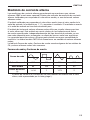
AC Measurement
AC measurements are usually displayed as RMS (root mean squared) values. Two
methods of AC measurement are average-responding RMS calibrated and true
RMS-reading.
The average-responding RMS calibrated method takes the average value of the input
signal, multiplies it by 1.11, and displays the result. This method is accurate if the
input signal is a pure sine wave.
The true RMS-reading method uses internal circuitry to read the true RMS value. This
method is accurate, within the specified crest factor limitations, whether the input
signal is a pure sine wave, a square wave, sawtooth wave, half wave or signal with
harmonics. The ability to read true RMS provides much more measurement versatil-
ity. The Greenlee CMT-90 is a true RMS meter.
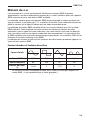
The Waveforms and Crest Factors table shows some typical AC signals and their
RMS values.
Waveforms and Crest Factors
Waveform
RMS Value 100 100 100 100
Rectified Value 90 100 87 64
Crest Factor*
(x)
1.414 1 1.73 2
* The crest factor is the ratio of the peak value to the RMS value; it is represented
by the Greek letter x.

9
CMT-90
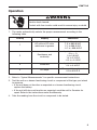
Operation
Electric shock hazard:
Contact with live circuits could result in severe injury or death.
1. The meter automatically selects the proper measurement according to the
following table.
Priority Display Conditions
1
AC volts or DC volts,
whichever is greater
Input at terminals is
1.3 to 999.9 VAC
2.1 to 999.9 VDC
-0.7 to -999.9 VDC
2
Resistance and
continuity
Input at terminals is
0 to ∞ Ω
0 to 0.9 VAC
1.0 to 2.0 VDC
-0.2 to -0.4 VDC
3 Diode test
Input at terminals is
0.4 to 0.8 VDC
4 AC amps
AC current through jaw is
0.9 to 600.0 A
2. Refer to “Typical Measurements” for specific measurement instructions.
3. Test the unit on a known functioning circuit or component of the type you intend
to measure.
• If the unit does not function as expected on a known functioning circuit,
replace the battery.
• If the unit still does not function as expected, send the unit to Greenlee for
repair. Refer to the instructions under the Warranty.
4. Take the reading from the circuit or component to be tested.

10
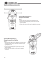
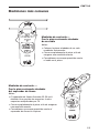
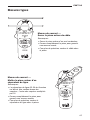
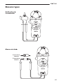
Typical Measurements
Current Measurement—
Clamp Around Wire
Notes:
• Clamp the jaw around one conductor only.
• Close the jaw completely to ensure accurate
measurement.
• Center the wire in the jaw for highest accuracy.
Current Measurement—
Clamp Around Line Splitter
Notes:
• The Greenlee 93-30 Line Splitter is divided. One
section renders amps; the other renders amps
multiplied by 10.
• Close the jaw completely to ensure accurate
measurement.
• Center the line splitter in the jaw for highest
accuracy.

11
CMT-90
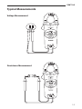
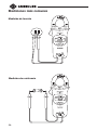
Typical Measurements
Voltage Measurement
Resistance Measurement

12
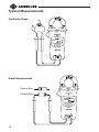
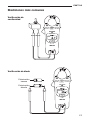
Typical Measurements
Continuity Check
Diode Measurement
Forward Bias
Reverse Bias

13
CMT-90
Accuracy
Refer to “Specifications” for operating conditions and temperature coefficient.
Accuracy is specified as follows: ± (a percentage of the reading + a fixed amount) at
23 °C ± 5 °C (73.4 °F ± 9 °F), 0% to 80% relative humidity.
Accuracy for AC measurements is specified for input crest factors that do not exceed
the values in the “Maximum Input Crest Factor” table on this page.
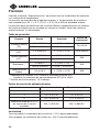
Accuracy Table
Characteristic Range Accuracy
Frequency
Range
AC Current
0.9 to 170.0 A ± (1.9% + 1 A)
50 to 60 Hz
170.1 to 600.0 A ± (1.9% + 2A)
AC Voltage* 1.3 to 999.9 V ± (1.5% + 0.3 V) 50 to 500 Hz
DC Voltage*
2.1 to 999.9 V ± (1.0% + 0.2 V)
N/A
-0.7 to -999.9 V ± (1.0% + 0.4 V)
Resistance**
0 to 999 Ω ± (2.0% + 4 Ω)
N/A
1.000 to 9.999 kΩ ± (2.0% + 0.004 kΩ)
Diode Test 0.4 to 0.8 V ± (1.0% + 0.2 V) N/A
* Input impedance: 4 kΩ nominal at voltages up to 30 V; increases with voltage
to approximately 375 kΩ at 1000 V
** Open circuit voltage: 1.5 V maximum
Maximum Input Crest Factor
Maximum Crest Factor Current Range Voltage Range
1.414 0.9 to 6.0 A 1.3 to 3.0 V
3 6.1 to 20.0 A 3.1 to 10.0 V
5 20.1 to 500.0 A 10.1 to 250.0 V
Linear decrease from 5to 1.5
over range shown
500.1 to 600.0 A 250.1 to 999.9 V
Continuity
Tone on: Circuit resistance is ≤ 25 Ω (approximately).
Tone off: Circuit resistance is ≥ 400 Ω (approximately).

14
Specifications
Display: 10,000-count LCD
Maximum Conductor Size: 33 mm (1.30")
Display update rate is 3 per second for voltage, diode test, and resistance;
2 per second for current
Duty Cycle (voltage above 30 V):
30 seconds ON (maximum)
2 minutes OFF (minimum)
Automatic Power Off: After approximately 20 minutes
Temperature Coefficient: 0.2 x (Accuracy) per °C below 18 °C or above 28 °C
Measurement Categories: Category III, 1000 V, and Category IV, 600 V
Operating Conditions:
Temperature:
0 °C to 30 °C (32 °F to 86 °F), 0% to 80% relative humidity
30 °C to 40 °C (86 °F to 104 °F), 0% to 75% relative humidity
40 °C to 50 °C (104 °F to 122 °F), 0% to 45% relative humidity
Altitude: 2000 m (6500') maximum
Indoor use only
Storage Conditions: –20 °C to 60 °C (–4 °F to 140 °F),
0% to 80% relative humidity
Remove battery
Pollution Degree: 2
Battery: 9 V battery (NEDA 1604, JIS 006P or IEC 6F22)
Battery Life: Approximately 250 hours with alkaline battery

15
CMT-90
Measurement Categories
These definitions were derived from the international safety standard for insula-
tion coordination as it applies to measurement, control, and laboratory equipment.
These measurement categories are explained in more detail by the International
Electrotechnical Commission; refer to either of their publications: IEC 61010-1 or
IEC60664.
Measurement Category I
Signal level. Electronic and telecommunication equipment, or parts thereof. Some
examples include transient-protected electronic circuits inside photocopiers and
modems.
Measurement Category II
Local level. Appliances, portable equipment, and the circuits they are plugged into.
Some examples include light fixtures, televisions, and long branch circuits.
Measurement Category III
Distribution level. Permanently installed machines and the circuits they are hard-
wired to. Some examples include conveyor systems and the main circuit breaker
panels of a building’s electrical system.
Measurement Category IV
Primary supply level. Overhead lines and other cable systems. Some examples
include cables, meters, transformers, and other exterior equipment owned by the
power utility.
Statement of Conformity
Greenlee Tools, Inc. is certified in accordance with ISO 9001 (2000) for our Quality
Management Systems.
The instrument enclosed has been checked and/or calibrated using equipment that
is traceable to the National Institute for Standards and Technology (NIST).

16
Maintenance
Electric shock hazard:
• Do not attempt to repair this unit. It contains no user-serviceable parts.
• Do not expose the unit to extremes in temperature or high humidity.
Refer to “Specifications.”
Failure to observe these precautions may result in injury and can damage the unit.
Battery Replacement
Electric shock hazard:
Before removing the case or battery cover, remove the test leads (or jaw) from the
circuit and shut off the unit.
Failure to observe this warning could result in severe injury or death.
1. Disconnect the unit from the circuit.
2. Remove the screws from the battery cover.
3. Remove the battery cover.
4. Replace the battery. Observe polarity.
5. Replace the cover and screws.
Cleaning
Periodically wipe the case with a damp cloth and mild detergent; do not use
abrasives or solvents.

17
CMT-90
Descripción
El Medidor digital con pinza modelo CMT-90 de Greenlee es un instrumento de
verificación capaz de efectuar los siguientes tipos de mediciones: tensión alterna
y continua, corriente alterna y resistencia. Esta unidad es de bolsillo y cabe
perfectamente en la palma de la mano. Sirve también para probar diodos y verificar
continuidad. El modelo CMT-90 es un multímetro de lectura de valores eficaces
reales.
Esta unidad determina automáticamente la función de medición según la entrada.
Posee una característica inteligente de retención de datos con alerta audible y visual
si la entrada cambia significativamente mientras la unidad se encuentra en modo
HOLD (RETENCIÓN DE DATOS EN PANTALLA). La unidad se activa automáticamente
en modo HOLD cuando la pinza se retira de un conductor durante la medición de
corriente de CA. Lleva a cabo una autoverificación y muestra aproximadamente
la capacidad restante de la pila durante la secuencia de encendido. Se puede
inhabilitar la característica de apagado automático si así se desea.
La pantalla se ilumina automáticamente para ayudar a visualizar objetos en áreas
oscuras.
Acerca de la seguridad
Es fundamental observar métodos seguros al utilizar y dar mantenimiento a las
herramientas y equipo Greenlee. Este manual de instrucciones y todas las marcas
que ostenta la herramienta le ofrecen la información necesaria para evitar riesgos
y hábitos poco seguros relacionados con su uso. Siga toda la información sobre
seguridad que se proporciona.
Propósito de este manual
Este manual de instrucciones tiene como propósito familiarizar a todo el personal
con los procedimientos de operación y mantenimiento seguros para el Medidor con
pinza, modelo CMT-90 de Greenlee.
Mantenga siempre este manual al alcance de todo el personal.
Puede obtener copias adicionales de manera gratuita, previa solicitud en
www.greenlee.com.
CONSERVE ESTE MANUAL
Todas las especificaciones son nominales y pueden cambiar conforme tengan lugar mejoras de
diseño. Greenlee Tools, Inc. no se hace responsable de los daños que puedan surgir de la mala
aplicación o mal uso de sus productos.
® Registrado:El color verde para instrumentos de verificación eléctricos es una marca
registrada de Greenlee Tools, Inc.
¡No deseche ni descarte este producto!
Para información sobre reciclaje, visite www.greenlee.com.

18
Importante Información sobre Seguridad
SÍMBOLO DE ALERTA
SOBRE SEGURIDAD
Este símbolo se utiliza para indicar un riesgo o práctica poco segura que podría
ocasionar lesiones o daños materiales. Cada uno de los siguientes términos
denota la gravedad del riesgo. El mensaje que sigue a dichos términos le indica
cómo puede evitar o prevenir ese riesgo.
Peligros inmediatos que, de no evitarse, OCASIONARÁN graves lesiones o
incluso la muerte.
Peligros que, de no evitarse, PODRÍAN OCASIONAR graves lesiones o incluso la
muerte.
Peligro o prácticas peligrosas que, de no evitarse, PUEDEN OCASIONAR lesiones
o daños materiales.
Lea y entienda este documento antes de manejar esta
herramienta o darle mantenimiento. Utilizarla sin comprender
cómo manejarla de manera segura podría ocasionar un
accidente y, como resultado de éste, graves lesiones o incluso
la muerte.

19
CMT-90
Importante Información sobre Seguridad
Peligro de electrocución:
El contacto con circuitos activados podría ocasionar graves
lesiones o incluso la muerte.
Peligro de electrocución e incendio:
• No exponga esta unidad ni a la lluvia ni a la humedad.
• No utilice esta unidad si se encuentra mojada o dañada.
• Utilice cables de prueba y accesorios que sean apropiados para la aplicación
que se va a realizar. Consulte la información sobre categoría y voltaje nominal
del cable de prueba o el accesorio.
• Revise minuciosamente los cables de prueba o el accesorio, antes de utilizarlos.
Deberán estar limpios y secos, y su forro aislante deberá hallarse en buenas
condiciones.
• Utilícela únicamente para el propósito para el que ha sido diseñada por el
fabricante, tal como se describe en este manual. Cualquier otro uso puede
menoscabar la protección proporcionada por la unidad.
De no observarse estas advertencias podrían sufrirse graves lesiones o incluso la
muerte.
Peligro de electrocución:
• No aplique más del voltaje nominal entre dos terminales de entrada
cualesquiera, o entre una terminal de entrada cualquiera y una conexión a tierra.
• No toque las puntas de los cables de prueba ni ninguna parte del accesorio que
carezca de forro aislante.
De no observarse estas advertencias podrían sufrirse graves lesiones o incluso la
muerte.

20
Importante Información sobre Seguridad
Peligro de electrocución:
• No haga funcionar esta unidad con la caja o la tapa del compartimiento de las
pilas abierta.
• Antes de retirar la caja o la tapa del compartimiento de las pilas, retire del
circuito los cables de prueba (o la pinza), y apague la unidad.
De no observarse estas advertencias podrían sufrirse graves lesiones o incluso la
muerte.
Peligro de electrocución:
• A menos que vaya a medir tensión o corriente, apague y bloquee la energía.
Asegúrese de que todos los condensadores estén totalmente sin carga. No debe
haber tensión alguna.
• Al utilizar esta unidad cerca de equipo que genere interferencia
electromagnética quizá se obtenga una lectura inexacta e inestable.
De no observarse estas advertencias podrían sufrirse graves lesiones o incluso la
muerte.
Peligro de electrocución:
• No intente reparar esta unidad, ya que contiene partes que deben recibir
mantenimiento por parte de un profesional.
• No exponga la unidad a ambientes de temperatura extrema o altos niveles de
humedad. Consulte la sección “Especificaciones”.
• No conecte a tensión por más de 30 segundos.
De no observarse estas precauciones pudieran sufrirse lesiones o daños a la
unidad.
Peligro de electrocución:
No utilice el medidor para medir tensiones en circuitos que pudieran dañarse o
accionarse debido a la impedancia baja de entrada del medidor (aproximadamente
4 kΩ).
De no observarse esta advertencia pudieran sufrirse lesiones o daños a la unidad.
La page est en cours de chargement...
La page est en cours de chargement...
La page est en cours de chargement...
La page est en cours de chargement...
La page est en cours de chargement...
La page est en cours de chargement...
La page est en cours de chargement...
La page est en cours de chargement...
La page est en cours de chargement...
La page est en cours de chargement...
La page est en cours de chargement...
La page est en cours de chargement...
La page est en cours de chargement...
La page est en cours de chargement...
La page est en cours de chargement...
La page est en cours de chargement...
La page est en cours de chargement...
La page est en cours de chargement...
La page est en cours de chargement...
La page est en cours de chargement...
La page est en cours de chargement...
La page est en cours de chargement...
La page est en cours de chargement...
La page est en cours de chargement...
La page est en cours de chargement...
La page est en cours de chargement...
La page est en cours de chargement...
La page est en cours de chargement...
-
 1
1
-
 2
2
-
 3
3
-
 4
4
-
 5
5
-
 6
6
-
 7
7
-
 8
8
-
 9
9
-
 10
10
-
 11
11
-
 12
12
-
 13
13
-
 14
14
-
 15
15
-
 16
16
-
 17
17
-
 18
18
-
 19
19
-
 20
20
-
 21
21
-
 22
22
-
 23
23
-
 24
24
-
 25
25
-
 26
26
-
 27
27
-
 28
28
-
 29
29
-
 30
30
-
 31
31
-
 32
32
-
 33
33
-
 34
34
-
 35
35
-
 36
36
-
 37
37
-
 38
38
-
 39
39
-
 40
40
-
 41
41
-
 42
42
-
 43
43
-
 44
44
-
 45
45
-
 46
46
-
 47
47
-
 48
48


Greenlee CMT-90 Clamp-on Meter Manuel utilisateur
- Taper
- Manuel utilisateur
- Ce manuel convient également à
dans d''autres langues
Documents connexes
-
Greenlee CMT-80 Test Leads - 11372 Manuel utilisateur
-
Greenlee CMT-90 Manuel utilisateur
-
-
-
-
-
-
-
-