
Part Number 99875146-4
JULY 2008
43-MILLIMETER COMPATIBLE
SWIPE READER
TECHNICAL REFERENCE MANUAL
REGISTERED TO ISO 9001:2000
Phone: (562) 546-6400
Technical Support: (651) 415-6800
www.magtek.com
1710 Apollo Court
Seal Beach, CA 90740
FAX: (562) 546-6301

ii
Cop 08
Printed in the United States of America
lectronic or mechanical, for any purpose,
without the express written permission of MagTek, Inc.
MagTek is a registered trademark of MagTek, Inc.
REVISIONS
Rev Number
yright
©
1999-20
MagTek
®
, Inc.
Information in this document is subject to change without notice. No part of this document may be
reproduced or transmitted in any form or by any means, e
Date Notes
1 22 Oct 99 Initial Release
2
16 May 03 Tech
s from 2.4 V to 2.7 V.
Front Matter: added ISO line to logo, changed
Support phone number, added new warranty
statement, changed warranty from 90 days to 1
year; Sec 1, Specifications, power requirements:
Changed single and dual track
3 13 May 08 Updated dimensions drawing
4 07 July 08 Added Appendix A

iii
te
horized by MagTek to resell the products, in which event, this warranty
ll, at its
laced
e,
ek reserves the right to examine the
.
t,
a three (3) day shipping service. A Return Material Authorization (RMA) number must accompany
Y
DING ANY WARRANTY OF MERCHANTABILITY OR
O
DVISED OF
HE POSSIBILITY OF SUCH DAMAGES, OR FOR ANY CLAIM BY ANY OTHER PARTY.
BILITY UNDER THIS AGREEMENT IS LIMITED TO THE CONTRACT PRICE OF THE
NY
PLIED WARRANTY OF
KIND
CLUDING ANY NEGLIGENCE ON ITS PART, TO THE
STATED IN THIS SECTION
AND IN THE SECTION RELATING TO MAGTEK’S LIMITED WARRANTY.
LIMITED WARRANTY
MagTek warrants that the products sold to Reseller pursuant to this Agreement will perform in accordance with
MagTek’s published specifications. This warranty shall be provided only for a period of one year from the da
of the shipment of the product from MagTek (the “Warranty Period”). This warranty shall apply only to the
original purchaser unless the buyer is aut
shall apply only to the first repurchase.
During the Warranty Period, should this product fail to conform to MagTek’s specifications, MagTek wi
option, repair or replace this product at no additional charge except as set forth below. Repair parts and
replacement products will be furnished on an exchange basis and will be either reconditioned or new. All rep
parts and products become the property of MagTek. This limited warranty does not include service to repair
damage to the product resulting from accident, disaster, unreasonable use, misuse, abuse, customer’s negligenc
Reseller’s negligence, or non-MagTek modification of the product. MagT
alleged defective goods to determine whether the warranty is applicable.
Without limiting the generality of the foregoing, MagTek specifically disclaims any liability or warranty for
goods resold in other than MagTek’s original packages, and for goods modified, altered, or treated by customers
Service may be obtained by delivering the product during the warranty period to MagTek (1710 Apollo Court,
Seal Beach, CA 90740). If this product is delivered by mail or by an equivalent shipping carrier, the customer
agrees to insure the product or assume the risk of loss or damage in transit, to prepay shipping charges to the
warranty service location and to use the original shipping container or equivalent. MagTek will return the produc
prepaid, via
all returns.
MAGTEK MAKES NO OTHER WARRANTY, EXPRESS OR IMPLIED, AND MAGTEK DISCLAIMS AN
WARRANTY OF ANY OTHER KIND, INCLU
FITNESS FOR A PARTICULAR PURPOSE.
EACH PURCHASER UNDERSTANDS THAT THE MAGTEK PRODUCT IS OFFERED AS IS. IF THIS
PRODUCT DOES NOT CONFORM TO MAGTEK’S SPECIFICATIONS, THE SOLE REMEDY SHALL BE
REPAIR OR REPLACEMENT AS PROVIDED ABOVE. MAGTEK’S LIABILITY, IF ANY, TO RESELLER
OR TO RESELLER’S CUSTOMERS, SHALL IN NO EVENT EXCEED THE TOTAL AMOUNT PAID TO
MAGTEK BY RESELLER UNDER THIS AGREEMENT. IN NO EVENT WILL MAGTEK BE LIABLE T
THE RESELLER OR THE RESELLER’S CUSTOMER FOR ANY DAMAGES, INCLUDING ANY LOST
PROFITS, LOST SAVINGS OR OTHER INCIDENTAL OR CONSEQUENTIAL DAMAGES ARISING OUT
OF THE USE OF OR INABILITY TO USE SUCH PRODUCT, EVEN IF MAGTEK HAS BEEN A
T
LIMITATION ON LIABILITY
EXCEPT AS PROVIDED IN THE SECTIONS RELATING TO MAGTEK’S LIMITED WARRANTY,
MAGTEK’S LIA
PRODUCTS.
MAGTEK MAKES NO OTHER WARRANTIES WITH RESPECT TO THE PRODUCTS, EXPRESSED OR
IMPLIED, EXCEPT AS MAY BE STATED IN THIS AGREEMENT, AND MAGTEK DISCLAIMS A
IMPLIED WARRANTY, INCLUDING WITHOUT LIMITATION ANY IM
MERCHANTABILITY OR FITNESS FOR A PARTICULAR PURPOSE.
MAGTEK SHALL NOT BE LIABLE FOR CONTINGENT, INCIDENTAL, OR CONSEQUENTIAL
DAMAGES TO PERSONS OR PROPERTY. MAGTEK FURTHER LIMITS ITS LIABILITY OF ANY
WITH RESPECT TO THE PRODUCTS, IN
CONTRACT PRICE FOR THE GOODS.
MAGTEK’S SOLE LIABILITY AND BUYER’S EXCLUSIVE REMEDIES ARE

iv
FCC Warning Statement
ith
rference in which case the user will be
quired to correct the interference at his own expense.
Canadian DOC Statement
ut in
e Radio Interference Regulations of the Canadian Department of Communications.
e Réglement sur le brouillage radioélectrique
édicté par les ministère des Communications du Canada.
CE STA DARDS
requirements was performed by an independent laboratory. The unit under test was
und compliant to Class A.
UL/CSA
This product is recognized per Underwriter Laboratories and Canadian Underwriter Laboratories 1950.
ing is clearly recognizable, either as
written words like “Pb-free” or “lead-free”, or as another clear symbol ( ).
This equipment has been tested and found to comply with the limits for a Class A digital device,
pursuant to Part 15 of FCC Rules. These limits are designed to provide reasonable protection against
harmful interference when the equipment is operated in a commercial environment. This equipment
generates, uses, and can radiate radio frequency energy and, if not installed and used in accordance w
the instruction manual, may cause harmful interference to radio communications. Operation of this
equipment in a residential area is likely to cause harmful inte
re
This digital apparatus does not exceed the Class A limits for radio noise for digital apparatus set o
th
Le présent appareil numérique n’émet pas de bruits radioélectriques dépassant les limites applicables
aux appareils numériques de las classe A prescrites dans l
N
Testing for compliance to CE
fo
RoHS STATEMENT
When ordered as RoHS compliant, this product meets the Electrical and Electronic Equipment (EEE) Reduction
of Hazardous Substances (RoHS) European Directive 2002/95/EC. The mark

v
TABLE OF CONTENTS
SE 1
1
1
SE
3
4
5
5
5
5
APPENDIX A. DRAWINGS .........................................................................................................................7
FIGURES
3
5
igure A-1. 43mm Dimensions ----------------------------------------------------------------------------------------------- 8
TABLES
4
able 2-2. I/O Connector for Dual Track, 8 Pin--------------------------------------------------------------------------- 4
CTION 1. FEATURES AND SPECIFICATIONS.....................................................................................
CONFIGURATIONS .................................................................................................................................
SPECIFICATIONS....................................................................................................................................
REFERENCE DOCUMENT......................................................................................................................1
CTION 2. INSTALLATION......................................................................................................................3
MOUNTING...............................................................................................................................................
CONNECTORS.........................................................................................................................................
TIMING......................................................................................................................................................
DATA.........................................................................................................................................................
STROBE ...................................................................................................................................................
CARD PRESENT......................................................................................................................................
Figure 1-1. 43-millimeter Compatible Swipe Reader--------------------------------------------------------------------vi
Figure 2-1. Reader Mounting Dimensions (Typical)---------------------------------------------------------------------
Figure 2-2. Timing ---------------------------------------------------------------------------------------------------------------
F
Table 2-1. I/O Connector for Single Track, 8 Pin-------------------------------------------------------------------------
T

vi
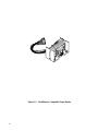
Figure 1-1. 43-millimeter Compatible Swipe Reader

1
SECTION 1. FEATURES AND SPECIFICATIONS
The 43-millimeter OEM Swipe Reader has a TTL level interface and is designed for use in retail,
access control, and time and attendance environments. This Reader is in compliance with
industry specifications, including ANSI/ISO Standards 7810, 7811-1 through -6, 7812, and 7813
The Reader can be customized. Bidirectional read capability is available.
CONFIGURATIONS
Configurations and part numbers are as follows:
Part Number Read Cable Length
21044001 Track 1 & 2 3.386" (86mm)
21044002 Track 2 & 3 3.386" (86mm)
21044003 Track 2 3.386" (86mm)
21044004 Track 1 & 2 8.661” (220mm)
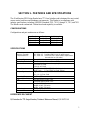
SPECIFICATIONS
IEC:
Meets or Exceeds
Requirements for:
IEC 1000-4-2 ESD (Electro Static Discharge)
IEC 1000-4-3 Radiated EMC Field (2X requirement)
IEC 1000-4-4 Electrical Fast Transient Burst requirement
(transmission on I/O cable)
Flammability Meets UL94V-0
Recording Method Two-Frequency Coherent Phase (F2F)
Speed Card speed through the unit may vary from:
2-125 ips at 75 bpi
2-60 ips at 210 bpi
Power Requirements Single Track: 2.7 to 5.5VDC at 1mA, typical
Dual Track: 2.7 to 5.5VDC at 2mA, typical
Output Signal Levels V
ol
= 0.4V at 2mA
V
oh
= V
cc
-0.5V at -2mA
Operating Temperature -30
o
C to 70
o
C
Operating Humidity 10% to 90% relative humidity
Life 300,000 passes Single Track
1,000,000 passes Dual Track
Dimensions Length: 1.693" (43mm)
Height: 0.902" (22.9mm)
Width: 0.866" (22.0mm)
Cable Length: See configuration table above
Connector See Section 2, Connectors
REFERENCE DOCUMENT
I/O Interface for TTL Swipe Readers, Technical Reference Manual, P/N 99875148

43-Millimeter Compatible Swipe Reader
2

3
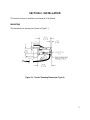
SECTION 2. INSTALLATION
This section consists of installation and checkout of the Reader.
MOUNTING
The dimensions for mounting are shown in Figure 2-1.
Figure 2-1. Reader Mounting Dimensions (Typical)

43-Millimeter Compatible Swipe Reader
4
CONNECTORS
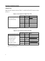
Single Track I/O Connector is shown in Table 2-1, and the Dual Track I/O Connector is shown
in Table 2-2.
Table 2-1. I/O Connector for Single Track, 8 Pin
Pin Number Color Signal
Connector for Single Track, 8 Pin 1 Brown GND
JAE IL-Y-8S-S15C3 2 Gray STROBE
1.5mm Contact Spacing 3 White DATA
4 Blue CARD PRESENT
5 NC
6 NC
7 NC
8 Red V
CC
Note:
V
CC
= 2.4 to 5.5 VDC
Table 2-2. I/O Connector for Dual Track, 8 Pin
Pin Number Color Signal
Connector for Dual Track, 8 Pin 1 Brown GND
JAE IL-Y-8S-S15C3 2 Gray STROBE (Tk 2)
1.5mm Contact Spacing 3 White DATA (TK 2)
Mates to JAE Headers: 4 Blue CARD PRESENT (Tk2)
Straight Pin Header: 5 Yellow *STROBE (TK 1)
IL-Y-8P-S15T2-EF 6 Orange *DATA (TK 1)
Right Angle Pin Header: 7 Green *CARD PRESENT (TK 1)
IL-Y- 8P-S15L2-EF 8 Red V
CC
* Track 1 will be designated Track 3 in P/N 21044002.
Note:
V
CC
= 2.4 to 5.5 VDC

Section 2. Installation
5
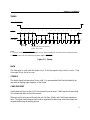
TIMING
CARD PRESENT
DATA
STROBE
1 1 1 0 0 0 0 0 1 1 0
0 0 0 0
Bit
Time
STROBE WIDTH APPROXIMATELY
25-50% OF BIT TIME
Notes:
1. Time out of the CARD PRESENT signal occurs approximately 150 ms after the last strobe transition.
2. DATA is valid 1.0μ sec before the negative edge of STROBE.
Figure 2-2. Timing
DATA
The Data signal is valid while the strobe is low. If the Data signal is high, the bit is a zero. If the
Data signal is low, the bit is a one.
STROBE
The Strobe signal indicates when Data is valid. It is recommended that Data be loaded by the
user with the leading edge (negative) of the Strobe.
CARD PRESENT
Card Present will go low after 14/15 flux reversals from the head. Card Present will return high
150 milliseconds after the last flux reversal.
When no card is being moved through the unit, the Data, Strobe, and Card Present signals are
high. The signal timing diagram shown above represents the data along with other signals that
are generated during the reading process.

43-Millimeter Compatible Swipe Reader
6

7
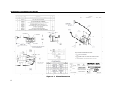
APPENDIX A. DRAWINGS
The drawing shown in this section show the mounting dimensions of the 43mm Reader.
21044001- Dimensions drawing for 43mm reader

43-Millimeter Compatible Swipe Reader
8
Figure A-1. 43mm Dimensions
-
 1
1
-
 2
2
-
 3
3
-
 4
4
-
 5
5
-
 6
6
-
 7
7
-
 8
8
-
 9
9
-
 10
10
-
 11
11
-
 12
12
-
 13
13
-
 14
14


dans d''autres langues
- English: Magtek Rails User manual
Documents connexes
-
Magtek Mini Swipe Card Reader Technical Reference Manual
-
-
Magtek Rails Technical Reference Manual
-
-
-
Magtek DynaPro Go Manuel utilisateur
-
-
-
-
Magtek iDynamo Manuel utilisateur