Fedders 23-11-2194N-001 s Installation & Operation Manual
- Catégorie
- Climatiseurs split-system
- Taper
- Installation & Operation Manual

PORTABLE AIR
Room Air Conditioner
Acondicionador de Aire
Climatiseur
Dehumidifer
Deshumedecedor
D6shumidificateur
Air Purifier
Purificaci6n de Aire
Epurateur d'air
Including Service
Incluidos mantenimiento
Avec service

ENGLISH
Electrical Requirements ...... 2
Warning
Notice
Important Grounding Requirements
Installation ........................... 3
Before starting your unit
Description of Parts on the Portable Ci_oling Unit
Window & Mobile Installation
Window Adapter Application
Ci_oling Through a Door Application
Operation ............................. 6
Control Panel
Power C_ntml Mode C_ntml Display C_ntml
Time/Temperature Ci_ntm/s Timer Ci_ntmls
Warning Lights
Draining the water
Upper Drain Valve
Ventibtion
Inserting Charcoal Filters
Ventilation mode
Cleaning & Maintenance
Cleaning the Filter
Bottom Drain Valve
Before using at the start of a season
When transporting the unit or storing the unit after
the season
Service ............................... 11
h'oubleshooting
ESPANOL
Requistos para
la el_ctricos ....................... 12
Aviso
Aviso
Requistos importantes para la conexidn a tierra
Instalaci6n ......................... 1 3
Antes de encender su unidad
Descripcidn die bs partes diela unidad die enffiamiento
port_1til
Ventana y Port_ftil Instabci6n
C_locacidn del adaptador de ventana
Aire acondicionado poniendo la unidad en una puerta
Funcionamiento ................. 16
Tab/era de Control
C_ntml de a/imentacidn - Control de modo
C_ntml de pantalla - C_ntmles de horn/temperature
C_ntmles de/mloj Lutes die advertencia
Dmnaje del Agua
V_#wlb de drenaje superior
Ventibcidn
C_locacidn de los filtms die carbdn
Modo die ventilaci6n
Limpieza y mantenimiento
Limpieza del filtm
V_1lwlb de drenaje inferior
Antes de usar b unidad al comienzo dieb estaci6n
Si se transporta la unidad o se guarda despu6s
de/a estaci6n
Servicio .............................. 21
Determina( idn dieaverfas
FRAN_AIS
Exigences _lectrique ......... 22
Avertissement
Avis
Importantes exigences de mise ,_/a terre
Montage ............................. 23
Avant de mettre l'appareil en marche
Description diespi_ces du climatiseur portatif
Fen_tm & Mobile Instalbtion
Adaptation pour montage dans une fen6tre
C/imatisation /orsque /'appamil est mont4
dans une porte
Fonctionnement ................. 26
Tableau de (__mmande
Intermpteur Mode Affichage Ck_mmandes
d'heure et de temp6rature - Commandes de
minuterie- Voyants avertisseurs
Vidande die/'eau
Robinet de vidange sup6rieur
Ventilation
Insertion des fi/tres ,_air au charbon
Mode Ventilateur
Nettoyage et entretien
Nettoyage flu fi/tre
Robinet de vidange inf_Srieur
Avant le d_but de/a saison
Avant die transporter l'appareil ou die
le ranger la saison
Service ............................... 32
D6pannage

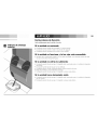
Electrical Shock Hazard
1. Plug unit only into grounded electrical outlet.
2. Do not use an extension cord or plug adapter
with this unit.
3. Do not operate unit with front removed.
Failure to follow the above precautions couldresult in electrical
shock, fire or personal injury.
If the unit has a serial plate rating of 115 volts and up to
and including 7.5 anlps, the unit nlay be on a fuse or circuit
breaker with other devkes. However, the maximum amps of
all devices on that fuse or circuit breaker cannot exceed the amps
of the fuse or circuit breaker.
The location of tile serial plate that _lpplies to this nlodel
call be found on the back page of this manual.
Notice
Do not operate this unit without proper time delay circuit
protection. Refer to serial plate for proper power supply
requirements.
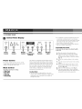
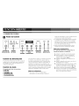
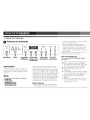
RECOMMENDED CIRCUIT WIRE SIZES
(Asinstalledper building c(;de)
PROTECTORSIZE WIRE GA UGF
15 AMP #1/! MINIMUM
20 AMP #12 MINIMUM
_0 AMP #10 MINIMUM
@©©@
I I5V 230V 230V 230V
15A 15A 20A 30A
For Your Safety:
• Do not store or use gasoline or other flanlmable vapors
and liquids in the vicinity of this or ally other appliance.
The filmes (:all create a fire hazard or explosion.
Power Supply: 115
AC Only I-
125 V, 15 A
Minimum Wire Size: #14 (A.
Circuit Protector:
or Circuit i
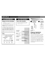
1. ELECTRICAL REQUIREMENTS
Grounded
Single outlet
three-prong grounding
wall receptacle wall receptacle
Three-prong
grounding plug
Important
Grounding Requirements
Your unit will operate on any 115 volt, 3-pronged
(grounded), 60 Hz circuit. A separate line is not
required, but it is advisable not to overload the
circuit with heavy duty appliances such as wash-
ing machines, etc. For your safety, this unit is
equipped with a 3-pronged, grounding plug and
must be plugged into a properly grounded outlet
(Figs. 1 & 2). If your outlet is not of the proper
type, it is your responsibility to have the outlet
and wiring changed to the correct type. DO NOT
CUT OFF THE THIRD (GROUNDING) PRONG.
DO NOT USE AN ADAPTER.

2. BEFORE STARTING YOUR UNIT 3. LIST OF FIGURES
Important information
• Read the instruction manua] before operating
the unit for the first time. It contains important
information on operation, safety, maintenance,
service and warranty.
• Keep this instruction manua] for future reference.
• Do not start a damaged unit.
• The assembly and connection of the unit must
be carried out according to the instructions. If
they are not fo]]owed you run the risk of voiding
the warranty.
1, The power cord is located in the rear of
the unit.
2, Do not allow contact between the unit
and water.
3, Do not cover the air discharge and air intake
louvers of the unit.
4., Proper venting of the air to the exterior is
required at a[] times.
After turning off the system wait at least 3 minutes
before restarting it.
The unit has casters to ease movement. If it is neces-
sary to tilt the unit, it must first be emptied of water in
the internal tank using the drain valve at the bottom of
the unit. See the section When transporting the unit or
Storing the unit for the season.
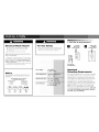
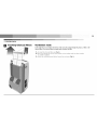
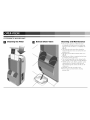
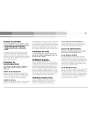
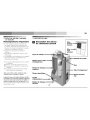
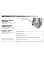
E] Description of Parts
on the Portable Cooling Unit
Drain Hose
Bracket to Store
Exhaust Tube
Upper Drain Valve
Serial Plate
Power Cord
Lower Drain Valve
Charcoal
Air Filter
Primary
Air Filter
Portable Cooling
Unit
Nozzle
Exhaust Tube
Intake Louvers

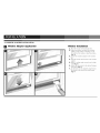
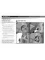
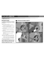
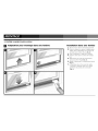
4. WINDOW & MOBILE INSTALLATION
_] Window Adapter Application
Window Installation
1, Place the nozzle in the exhaust tube.
2, Open the window and place the window
adapter in the window, extending it to fit
the width of the window, close the window
(Fig. 4).
3, Secure the window adapter to the window
sill.
4, insert the nozzle into the slot in the window
adapter.
5, Select a cooling mode; normal coo] or high
cool (Fig. 6).
6, Adjust the thermostat to the desired tempera-
ture setting (Fig. 6).
T, Air direction can be adjusted using the han-
dle found on the top of the control panel
(Fig. 6).

5
Mobile Installation
1. Place the nozzle in the exhaust tube.
2, Open the door slightly and position the
nozzle between the door and the door jamb
(Fig. 5).
3, Select a cooling mode; normal cool or high
cool (Fig. 6).
4. Adjust the thermostat to the desired tempera-
ture setting (Fig. 6).
5. Air direction can be adjusted using the han-
dle found on the top of the control panel
(Fig. 6).
Important: Do not over-stretch the exhaust tube or
make any unnecessary bends in it.
Cooling Through a Door Application
. r .
g

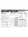
5. CONTROL PANEL
[_ Control Panel Display
CLEAN DRAIN
FILTER. WATER
@ @ @ @ @
fl160 LOW HIGH LOW DEHUMIDIFY
COOLCOOLFAN FAN
DISPLAY
TIME_°C_°F
TIMER/SET
@ @
START STOP
Power Mode Display Time/ Timer Warning
Control Control Control Temperature Controls Lights
Controls
Power Control
The power control turns the unit on and off.
A green light will indicate that the unit is ON,
if there is no light the unit if OFF.
Mode Control
The Mode Control has five settings:
• High Cool
• Low Cool
• High Fan
• Low Fan
• Dehumidify
The settings are adjusted with the Mode Control
button. A green light will indicate which setting is
currently being used. When either of the cooling
modes is selected, the unit will circulate and coo]
the air. if either of the fan modes is selected, the
unit will only circulate the air. When the dehu-
midify setting is selected, the unit will remove
moisture and circulate the air.
Cooling Mode
• The unit cools and dehumidifies at the same
time for more comfort. During the cooling mode
condensed water is released to the outside air
through the nozzle.
• In conditions of extreme humidity the unit will
accumulate condensed water in an internal
tank. At that time the drain water light will blink
indicating that the tank must be emptied. See
the section on Draining the Watel:
• Adjust cooling speed and thermostat setting to
suit your comfort requirements.
Dehumidification Mode
In this mode the unitreducesthe ambienthumidity
in theroom.
1. Place the nozzle in the exhaust tube.
2. Open the window and place the window
adapter in the window, extending it to fit
the width of the window. Close the window
(Fig. 4).
3. Secure the window adapter to the window
sill.
4. Insert the nozzle into the slot in the window
adapter.
5. Ensure that the upper drain valve is in the
closed position and that the rubber plug is
in place (Fig. 7 d).
6. Select the Dehumidifying mode (Fig. 6).
7. if the drain water light is blink, indicating
that the internal bucket is full, follow the rec-
ommended water draining procedure

7
Display Control
The display control is used to change the current dis-
play setting. There are three settings on the display:
• Temperature/Fahrenheit
• Temperature/Celsius
• Timer
The display will return from the time setting to the
Fahrenheit setting after the control has not been
depressed for five seconds. The temperature on
the display is the set temperature, it is NOT the
actual room temperature.
Time/Temperature Controls
These buttons are used to change the set temperature,
the clock, start time, and stop time.
Temperature Change
Select either Fahrenheit or Celsius on the display
by using the Display Control, then change the set
temperature in increments of 1° using the
Time/Temperature.
Time Change
Select the time display with the Display Control
and change the clock with the Time/Temperature
controls. The time will increase or decrease in one
minute increments with each depression. If either
the up or down buttons is held down, the time
will change continuously until the button is
released. The AM and PM lights will change
appropriately with the clock.
Timer Controls
The Timer Controls can be used to set a time for the
air conditioner to start as well as a time for the air
conditioner to shut off.
Setting a Start/Stop Time
Depress the start or stop button. The display will
now show a time. Use the Time/Temperature
controls to set the desired start/stop time. After
reaching the desired start/stop time, release the
Time/Temperature control button. The timer will
be set after no buttons have been depressed for
five seconds. A light above the start and stop but-
tons will indicate when the timer is activated.
Shutting the Timer Function OFF
If the Start function is set:
Depress the Start button for three seconds.
The light will go off and the start function is
now deactivated.
If the Stop function is set:
Depress the Stop button for three seconds.
The light will go off and the stop function is
now deactivated.
Warning Lights
These lights will come on when the air conditioner
needs attention.
Clean Filter Light
This light indicates that the filter needs to be
cleaned. The air conditioner will continue to run
even when the light is on. However, the filter
should be cleaned as soon as possible after the
light comes on. After cleaning the filter, press both
Time/Temperature controls simultaneously to reset
the filter monitor.
Drain Water Light
This light indicates that the internal water bucket
needs to be drained. The unit will not operate
unti] the water has been drained. See section 6
of the owner_" manual for instructions on how to
drain the water. The air conditioner must be set to
dehumidify when the water is drained.

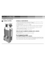
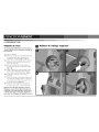
6. DRAINING THE WATER
iiiiii--i
Draining the water
If the red light is lit, indicating that the internal
bucket is full, follow the recommended water draining
procedure:
D
Upper Drain Valve
1. The unit must be switched to the off position.
2. Place a container under the upper drain
valve and remove the rubber plug from the
upper drain valve (Fig. 7 a, b, c).
3. Insert the drain hose on the upper drain
va]ve pointing it into the container.
4. Turn the upper drain valve from the dosed
position to the open position (Fig. 7 b).
5. Turn the unit on, turn the thermostat to the
warmest setting and the switch to the dehu-
midify mode. The unit will turn on, allowing
the pump to run and drain the water from
the unit (Fig. 6).
6. When the water stops draining from the unit,
turn off the unit.
7. Close the upper drain valve, remove the
drain hose, remove the container of water,
put the rubber plug back in the upper drain
valve (Fig. 7 d).
8. The unit can be turned to any operating
mode.
Important: When changing the operating mode back to
cooling do not forget to put the rubber plug back in
and turn the upper drain valve 90 ° to the right or to
the closed position. If this is not done the water will
come out of the unit when it is switched on.

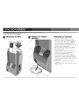
7. VENTILATION
Ventilation mode
In this mode the air is recycled to the interior of the room after passing through the primary air filter or the
charcoal filters. The charcoal filters act against odors, bacteria, and dust.
1. To insert the charcoal filters see (Fig. 8).
2, Place the exhaust tube in the same position as the cooling mode for either window
or mobi]e installation,
3, Select the ventilation speed desired; normal or maximum (Fig. 6).

8. CLEANING & MAINTENANCE
I_1 Cleaning the Filter
Bottom Drain Valve
Cleaning and Maintenance
• The unit has a primary air filter that must
be cleaned with water every two weeks and
put back in the unit after it is completely dry
(Fig. 9).
• The charcoal purification filters should be
replaced with new every year so that the unit
performs we]].
• The fitting of the fi]ters shou]d be done as in
(fig. 8).
• Only one set of filters is required on the frame
to maintain cooling efficiency.
• The air discharge grille can be cleaned with a
rag or sponge, warm water and mild detergent.
• NEVER use hot water, bleach, gasoline, acids,
cleaning fluid or a brush to clean the unit.
This will damage the cabinet and the air dis-
charge area.
• DO NOT wash the unit with a hose.
• Remove charcoal insert before cleaning
primary filter.

.........ili/I l ¸¸¸¸¸¸¸¸¸¸:1%:¸!:!:!:
Before using at the start of a
season
• Turn the unit on for tour to five hours to
dry it out.
• Clean the air filter.
• Clean the cabinet and air discharge areas
if necessary.
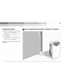
When transporting
the unit or storing the unit
after the season
Drain excess water from the bottom tank by plac-
ing a pan under the lower drain, remove the rub-
ber plug, and let the water drain into the pan.
When the water stops draining out, replace the
lower drain plug and remove the pan of water
(Fig. 10). To drain water using the upper drain
valve refer to the section entitled "Draining the
W_ter'.
Service Instructions
Read carefully before calling for service.
If the unit fails to start
• Make sure the unit is plugged into an outlet.
• Make sure the unit is not in the off position.
• Make sure the circuit breaker has not been tripped.
If the unit does not function and drain water light is blinking
• Make sure the unit is standing level, if the light is still on, empty the internal water tank.
(See the section on Draining Water).
If the unit does not cool sufficiently
• Make sure the exhaust tube and nozzle fit correctly to each other and to the window adapter.
• Make sure the exhaust tube is not bent.
• Make sure the upper drain valve is in the dosed position.
• Adjust the thermostat to a lower temperature.
• Make sure the exhaust tube and nozzle have nothing inside them.
If the unit is too loud
• Make sure the exhaust tube and nozzle fit correctly to each other and to the window mount.
• Make sure the exhaust tube and nozzle have nothing inside,

Peligro de
choque el_ctrico
1. Enchufe [a unidad en un toulacorriente con
conexi6n _ tierra.
2. No use un cord6n de extensi6n ni un adaptador
de enchufe par_ este unid_d.
3. No haga funcionar J_unidad sin 1_ parte frontal.
El no segu_ las advertenc_s anter_res podrfa causar un
choque el6ctrlco o una lesi6n personal.
Si en la pla(a de ndmero (If' serie hay una especifi(aN6n
de H5 voltios y hasta 7,5 amperios, la unidad puede corn
partir un fusible o interruptor de circuffo con otros disposi
tivos..Sit) embargo, el amperaje m_xlmo de tudus los
dispositivos en ese filsible o h)terruptor de c_uito no
puede exceder el amperaje del fusible o el h)terruptor de
circuito.
Para Iocalizar la placa (:on el n0mero de serie aplicable
a este illodelo, vea la p4gina posterior de este manual.
Aviso
No operar esta unidad sin la protecci6n adecuada de un cir-
cuito de tiempo retardado, consuJte [a pJaca (:on el n0mero
de serie para los suministros de cordente adecuados.
TAMANOS QUE SE RECOMIENDAN PARA
LOS ALAMBRES DEL CIRCUITO
(h)stalaci6n de acuerdo al c6dlgo de construcci6n)
TAMANO DEL PROTECTOR GROSOR DEL CABLE
15 AMP #14 MINIMUM
20 AMP #12 MINIMUM
_0 AMP #10 MINIMUM
@©©@
I I5V 230V 230V 230V
15A 15A 20A 30A
Para Su Seguridad:
• No guarde ni use gasolina u otros vapores o I[quidos
inflamables cerca de esta unidad ni de cualquier otto
artefacto. [ os vapores pueden (rear el riesgo de incendio
o explosi6n.
Suministro
de corriente:
Tomacorriente
que serequiere:
Tamaffo mmlmo
del alambre:
Protector deI
circuito:
115'
solamente
De 3
1251
No. 14 M._
alambre de
1. REQUISTOS ELECTRICOS
il
conexi6n de tierra
Enchufe fe tres patdlas con
conexi6n a tierra
Recept_culo E! Recept_culo
de pared de tres de pared con un
patillas con s61o tomacorri-
ente con
conexi6n a tierra
Requisitos importantes
para la conexi6n a tierra
Su unidad funcionar4 en cualquier circuito de 11,B
voltios, de 3 patillas (con conexi6n a tierra) y 60
Hz. no se requiere ]fnea separada, pero es aconse-
jable no sobrecargar el circuito con artefactos que
usan mucha corriente como m4quinas de ]avar
ropa, etc. Para su seguridad, esta unidad est4
equipada con un enchufe de 3 patillas de conex-
i6n a tierra y debe enchufarse en un tomacorri-
ente con ]a debida conexi6n a tierra (figuras 1
y 2). Si su tomacorriente no es del tipo adecuado,
usted tiene ]a responsabilidad de hacer que se
cambien tanto el tomacorriente como los alam-
bres al tipo adecuado. NO CORTE LA TERCERA
PATILLA DE CONEXI_)N A TIERRA. NO USE UN
ADAPTADOR.

2. ANTES DE ENCENDER SU UNIDAD
• Antes de usar la unidad por la primera vez, lea
el manual de instrucciones que contiene infor-
maci6n importante sobre su operaci6n, seguri-
dad, mantenimiento, servicio y garantfa,
• Guarde este manual de instrucciones para con-
sultar]o en el futuro,
• No encienda una unidad que est6 dafiada,
• El ensamblado y ]a conexi6n de ]a unidad debe
]]evarse a cabo de acuerdo alas instrucciones,
Si no se siguen, usted toma el riesgo de invali-
dar ]a garantfa,
Informaci6n importante
1, El cord6n de electricidad est,1 situado en ]a
parte posterior de ]a unidad.
2, No deje que ]a unidad est6 en contacto con
el agua.
3, No cubra ]as reji]]as de descarga y de toma
de aire de ]a unidad.
4, En todo momento se necesita una sa]ida
adecuada de] aire a] exterior.
Despu_s de apagar el sistema, espere pot Io menos
3 minutos antes de volver a encenderlo.
La unidad tiene ruedas para facilitar el movimiento.
Si es necesario inclinarla, se debe primero vaciar el
agua del tanque interno, usando la v_lvula de drenaje
en la parte inferior. Vea la sec_idn si se t!_nsporta o
alma_ ena la unidad durante la esta_idn.
3. LISTA DE FIGURAS
iiii!ii!ii!ii!ii!ii!ii!ii!ii!ii!ii!ii!ii!ii!ii!ii!ii!ii!ii!%i%i%i%
_] Descripci6n de las partes
de la unidad de
enfriamiento portatil
Manguera de
drenaje
F iI t ro
aire
de carb
Filtro _i I )!i
de aire
principal
Abrazadera para
almacenar el tubo
de escape
V_lvula de
drenaje superior
Placa con el
n_mero de serie
Cord6n de
electricidad
de
enfriamiento port_til
.ilia
Tubo de escape
illas de toma
de aire
V_lvula de drenaje
superior

4. VENTANA Y PORT,_TIL INSTALACION
I_1 Colocaci6n del adaptador de ventana
i
Instalaci6n en una ventana
1. Coloque la boquilla en el tubo de escape,
2. Abra la ventana y coloque el adaptador,
extendi#ndolo para que se acomode a la
anchura de la ventana; cierre la ventana
(Fig. 4).
3, Asegure el adaptador para la ventana en el
alf6izar de ]a ventana,
4, Inserte ]a boquilla en ]a ranura del adaptador
para ventana,
5, Selecciones un modo de enfriamiento:
normal o alto (Fig. 6).
6, Ajuste el termostato a ]a temperatura que
desea (Fig. 6).
7, La direcci6n del aire puede graduarse usan-
do ]a palanca que se encuentra en ]a parte
superior del panel de control (Fig. 6).

15
Instalaci_n portatil
1. ¢:oloque la boquilla en el tubo de escape,
2, Abra la puerta un poco y co]oque ]a boquilla
entre ]a puerta y ]a jamba (Fig. 3).
3, Seleccione un modo de enfriamiento: normal
o alto (Fig. 6).
4, Ajuste e] termostato a ]a temperatura que
desea (Fig. 6).
5, La direcci6n del aire puede ajustarse usando
]a palanca que se encuentra en ]a parte supe-
rior de] panel de control (Fig. 6).
Importante: No extienda el tubo de escape ni Io doble
sin necesidad.
Aire acondicionado poniendo la unidad en una puerta
. r .

5. TABLERO DE CONTROL
Panel de Control
@ @ @ @ @
HIGH LOW HIGH LOW DEHUMIDIFY
COOLCOOL FAN FAN
DISPLAY
TIME*°C*°F
CLEAN DRAIN
TIMER/SET FILTER WATER
@ @
START STOP
modo de enfriamiento, el agua condensada pasa
a] exterior por medio de ]a boqui]]a,
• En condiciones de humedad extrema ]a unidad
acumular_i e] agua condensada en un tanque
interno, En este caso ]a ]uz roja se encender,_i
para indicar que se debe vaciar el tanque, Vea
la secci6n sobre Drenaje del agua.
• Ajuste ]a velocidad de enfriamiento y el ter-
mostato para [ograr ]a temperatura deseada.
Control de Control Control
Alimentaci6n de Modo de
Pantalla
Control de alimentaci6n
El control de alimentaci6n enciende y apaga ]a
unidad, La ]uz verde indica que ]a unidad est,_i
ENCENDIDA, Si no est.1 encendida ]a ]uz, ]a
unidad est4 APAGADA,
Control de modo
El control de modo tiene cinco posiciones:
• Frio alto
• Frio bajo
• Ventilador alto
• Ventilador bajo
• Deshumidificador
Controles de Controles Luces de
Hora/ del Reloj Advertencia
Temperatura
Las posiciones se ajustan con el bot6n de control
de modo, La ]uz verde indica que el modo se
encuentra actualmente en uso, Cuando se selec-
ciona uno de los dos modos de enfriamiento, ]a
unidad har,_i circular el aire y 1o enfriar_i, Si se
selecciona uno de los dos modos de venti]aci6n ]a
unidad s6]o har_i circular el aire, Cuando se selec-
ciona la funci6n de deshumidificaci6n, ]a unidad
eliminar_i la humedad y har_i circular el aire,
Modo de enfriamiento
• Para mayor confort, ]a unidad enfffa y
deshumedece al mismo tiempo. Durante el
Modo para deshumedecer
Enel modo de deshumedece_la unidad reducela
humedaddel ambienteen la habitaciGn.
1. Co]oque ]a boqui]]a en el tubo de escape.
2. Abra la ventana y co]oque el adaptador,
extendi6ndo]o para que se acomode a ]a
anchura de ]a ventana (Fig. 4).
3. Asegure el adaptador para ventana en el
alf_izar,
4, Inserte ]a boqui]]a en el espacio que hay en
el adaptador de ]a ventana,
5, Compruebe que ]a wilvula de drenaje superi-
or est6 en ]a posici6n de cierre y que el
tap6n de caucho est6 en su ]ugar (Fig. 7 d).
6. Escoja el modo de deshumedecer (Fig. 6).
7. Si ]a ]uz roja que indica que el ba]de interno
est,_i ]]eno se enciende, siga el procedimiento
que se recomienda para drenaje.

17
Control de pantalla
El control de pantalla seusa para cambiar la configu-
raci6n de pantalla actual. La pantalla puede presentar:
• Temperatura/Grados fahrenheit
• Temperatura/Grados centigrades
• Reloj
La pantalla volver,.i a pasar de mostrar el re]oj
a mostrar ]a temperatura en grados fahrenheit
despu6s de transcurridos 5 segundos sin que se
presione el control La temperatura que se muestra
en ]a panta]]a es ]a temperatura fijada, NO ]a tem-
peratura de ]a habitaci6n.
Controles de
hora/temperatura
Estos botones se usan para cambiar la temperatura
fijada, el reloj, la hora de comienzo y la hora de
finalizaci6n.
Cambio de la temperatura
Seleccione grados fahrenheit o cenfigrados en
]a panta]]a usando el control de panta]]a. Luego
cambie ]e temperatura fijada en incrementos de
] o usando e] control de tiempo/temperatura.
Cambio de la hora
Se]eccione ]a panta]]a de ]a hora con el control de
panta]]a y cambie e] re]oj con los contro]es de
hora/temperatura. La hora aumentar,.i o disminuir4
en incrementos de un minuto cada vez que pre-
sione el bot6n. Si mantiene presionado uno de los
dos botones, el tiempo cambiar4 continuamente
hasta que se suelte el bot6n. Las ]uces de AM y
PM cambian autom4ticamente al cambiar ]a hora.
Controles del reloj
Los controles del reloj se usan para fijar un horarlo
para clue se encienda el acondicionador de aire y un
horatio para que se apague.
Configuraci6n de la hora
de comienzo y finalizaci6n
Presione el bot6n de comienzo o finalizaci6n. La
pantalla mostrar,_i una hora. Use los controles de
tiempo/temperatura para fijar ]a hora de comien-
zo/finalizaci6n deseada. Despu6s de ]]egar a ]a
hora de comienzo/finalizaci6n deseada suelte el
bot6n de control de tiempo/temperatura. El reloj
quedar_i configurado despu6s de que no se haya
presionado ningOn bot6n durante cinco segundos.
Una ]uz sobre los botones de comienzo y final-
izaci6n indicar_i que el reloj est,1 activado.
Apagado de la funci6n de reloj
Siest_configuradala funci6nde Comienzo:
Mantenga presionado el bot6n de comienzo
durante 3 segundos. La luz se apagar,.i y ]a
funci6n de comienzo quedar_i desactivada.
Si est_ configurada la funci_n de Finalizaci_n:
Mantenga presionado el bot6n de fina]izaci6n
durante 3 segundos. La ]uz se apagar_i y ]a fun-
ci6n de fina]izaci6n quedar_i desactivada.
Luces de advertencia
Estasluces se encender_n cuando sea necesario que
preste atenci_n al acondicionador de aire.
Luz de limpieza de filtro
Esta luz indica que el filtro requiere ]impieza.
E] acondicionador de aire seguir,_i funcionando
aunque ]a ]uz est6 encendida. Sin embargo, cuan-
do esta ]uz se enciende, e] fi]tro debe ]impiarse ]o
antes posib]e. Despu6s de ]impiar e] fi]tro, pre-
sione los dos contro]es de hora/temperatura para
reinicia]izar e] monitor de] fi]tro.
Luz de drenaje de agua
Esta luz indica que la cubeta de agua interna debe
drenarse. La unidad no funcionar_i hasta que se
haya drenado el agua. (Vet la seccidn 6 del manu-
al del propietario para obtener instrucciones acer-
ca de cdrno drenar el agua.) El acondicionador de
aire debe ponerse en el modo de deshumidifi-
caci6n cuando se drena el agua.

6. DRENAJE DEL AGUA
iiiiii--i
Drenaje del agua
Si se enciende la luz roja que indica que el balde inter-
no estd Ileno, siga el procedimiento que se recomienda
para el drenaje:
1. Debe apagarse ]a unidad.
2. Co]oque el recipiente bajo ]a v,_ilvula de
drenaje superior y saque e] tap6n de caucho
de dicha v,_iivula (fig. 7 a, b, c).
3. Inserte ]a manguera de desagOe en ]a wilvu]a
de drenaje superior apuntando hacia dentro
de[ recipiente.
4. Mueva ]a wilvu]a de drenaje superior de
]a posici6n de apagado a ]a de encendido
(Fig. 7 b).
5, Encienda ]a unidad, ponga e] termostato en
]o m_is ca]iente y e] interruptor en posici6n
modo de deshumidificaci6n, y ]a unidad se
encender_i,
]o que permite que funcione ]a bombay
drene el agua (fig. 6).
6. Apague la unidad cuando ya no salga agua.
7. Cierre la wilvula de drenaje superior, saque
la manguera de drenaje, retire el recipiente
de agua y vuelva a poner el tap6n de caucho
en la v,_ilvula de drenaje superior (Fig. 7 d).
8. Ahora ]a unidad puede ponerse en el modo
de operaci6n que desee.
hnportante: Cuando cambie el mode de operaci6n nue-
vamente a enfriamiento, no se olvide de volver a poner
el tap6n y de girar la v_lvula de drenaje superior 90 ° a
la derecha o a la posici6n de cierre. Si esto no se hace,
saldr_ agua de la unidad cuando se encienda.
D
Valvula de drenaje superior

Z ii ¸ 19
7. VENTILACION
_] Colocaci_n de los filtros
de carb6n ..._
Modo de ventilaci6n
En este modo, el aire vuelve a circular en el interior de la habitaci6n despu_s de pasar por el filtro de aire pdmado
o los filtros de carb6n. Los filtros de carb6n sirven para combatir los malos olores, las bactedas y el polvo.
1. Para poner los filtros de carb6n (Fig. 8).
2. Co]oque el tubo de escape en ]a misma posici6n que para el modo de enfriamiento, ya sea para ]a
insta]aci6n en una ventana o para ]a insta]aci6n m6vi],
3, Se]eccione ]a ve]ocidad de venti]aci6n que desee: norma] o m_xima (fig. 6).
La page est en cours de chargement...
La page est en cours de chargement...
La page est en cours de chargement...
La page est en cours de chargement...
La page est en cours de chargement...
La page est en cours de chargement...
La page est en cours de chargement...
La page est en cours de chargement...
La page est en cours de chargement...
La page est en cours de chargement...
La page est en cours de chargement...
La page est en cours de chargement...
La page est en cours de chargement...
La page est en cours de chargement...
-
 1
1
-
 2
2
-
 3
3
-
 4
4
-
 5
5
-
 6
6
-
 7
7
-
 8
8
-
 9
9
-
 10
10
-
 11
11
-
 12
12
-
 13
13
-
 14
14
-
 15
15
-
 16
16
-
 17
17
-
 18
18
-
 19
19
-
 20
20
-
 21
21
-
 22
22
-
 23
23
-
 24
24
-
 25
25
-
 26
26
-
 27
27
-
 28
28
-
 29
29
-
 30
30
-
 31
31
-
 32
32
-
 33
33
-
 34
34


Fedders 23-11-2194N-001 s Installation & Operation Manual
- Catégorie
- Climatiseurs split-system
- Taper
- Installation & Operation Manual
dans d''autres langues
- English: Fedders 23-11-2194N-001 s
- español: Fedders 23-11-2194N-001 s
Documents connexes
-
Fedders 23-23-0338N-002 s Installation & Operation Manual
-
-
-
-
-
Autres documents
-
 Hampton Bay HBP070 Le manuel du propriétaire
-
 Hampton Bay PORTABLE AIR CONDITIONER Installation & Operation Manual
-
Maytag 22-11-2222N-003 Manuel utilisateur
-
-
-
-
Home Styles 73005052 Guide d'installation

