La page est en cours de chargement...

i iiiiiiiii
_iii ii i
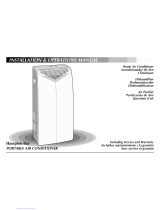
PORTABLE AIR CONDITIONER
Room Air Conditioner
Acondicionador de Aire
Climatiseur
Dehumidifier
Deshumedecedor
D6shumidificateur
Air Purifier
Purificaci6n de Aire
Epurateur d'air
Including Service and Warranty
lncluidos mantenimiento y la garantfa
Avec service et garantie

ENGLISH
Electrical Requirements ...... 1
Warning
Notice
Important Grounding Requirements
|nstallation ........................... 2
Befol'e starting yOLIFLInit
Description of Parts on the Portable Cooling Unit
Window & Mobile Instalbtion
Window Adapter Application
Cooling Through a Door Application
Operation ............................. 5
Control Panel
Power Contlol Mode Contlol Display Contlol
Time/Temperature Controls Timer Controls
Warning Lights
Draining the water
Upper Drain Valve
Ventilation
Inserting Charcoal Fi/telts
Ventilation mode
Cleaning & Maintenance
Cleaning the Filter
Bottom Drain Valve
Before using at the start of a season
When transporting the unit or storing the unit after
the season
Service ............................... 10
h'oubleshooting
Service o1 Parts Required
Warranty ............................. 10
ESPA OL
Requistos para
la el6ctricos ....................... 12
Aviso
Aviso
Requistos importantes para /a conexidn a tierra
|nstalaci6n ......................... 13
Antes dieencender su urlidad
Descripcidn de bs paltes dieb urlidad de erlfriamierlto
polt_til
Ventana y Port_itil Instalaci6n
Colocacidn del adaptador die ventana
Aire acorldiciorlado porfiendo b urlidad en una puerta
Funcionamiento ................. 16
Tablem die Control
Control die a/imentaci6n Control die modo
Control die pantalla Contmles die horn/temperature
Contmles del reloj Lutes de advertencia
Drenaje del Agua
V_ilvub die drenaje superior
Ventflacidn
Colocacidn die los fi/tros de cal_)dn
Modo die ventibcidn
Limpieza y mantenimiento
Limpieza del fihro
V_lvula die drenaje inferior
Antes die usar b unidad al comienzo dieb estacidn
Si se tmnspotta la unidad o se guarda despuds
die b estacidn
Servicio .............................. 21
Detemfinacidn dieaver[as
Necesidad die servicio o piezas
Garantia ............................. 21
FRANCAIS
Exigences _lectrique ......... 23
Avertissement
Avis
Importantes exigences die raise _ la terre
Nontage ............................. 24
Avant die mettre I'appareil en marche
Description diespi6ces du c/imatiseur portatif
Fen_tre & Mobile Installation
Adaptation pour montage dans une fen_tre
Climatisation Ioltsque /'apparei/ est montd
darls une porte
Fonctionnement ................. 27
Tableau de Commande
Interrupteur Mode - Affichage Commandes
d'heure et de tempdrature Commarldes de
minuterie Voyants avertisseults
Vidande die I'eau
Robinet die vidange sup(_rieur
Ventibtion
Ir}sertion dies filtres b air au charbon
Mode Ventilateur
Nettoyage et entretien
Nettoyage du filtre
Robinet die vidange inf4rieur
Awmt le ddbut die la saison
Awmt die transporter I'appareil ou die
le ranger la saison
Service ............................... 32
D@_annage
R_parations ou pi6ces Savbrent n_cessaires
Garantie ............................. 32

Electrical Shock Hazard
1. Plug unit only into grounded electrical outlet.
2. [Do not use an extension cord or plug adapter
with this unit.
3. [Do not operate unit with (font removed.
Failure to follow the above precautions could result in electrical
sl_ock, fire or personal injury,
If the unit has a serial plate rating of 115 volts and up to
and including 7.5 amps, tile unit may be on a fuse or circuit
breaker with other devices. However, tbe maxbnum amps of
all devk'es on tbat fuse or circuit breaker cannot exceed the amps
of the fuse or circuit breaker.
] he location of the serial plate that applk's to this model
can be found on tile back page of this manual
Hotice
[)o not operate this ulfit without proper time dday drcuit
protection. ReFerto serial plate For proper power supply
requirements.
RECOMMENDED CIRCUI T WIRE SIZES
(As installed per building code)
PROTECTORSIZE WIRE GAUGE
15 AMP #14 MINIMUM
20 AMP #12 MINIMUM
_0 AMP #10 MINIMUM
@©©@
l lSV 230V 230V 230V
15A 15A 20A 30A
For Your Safety:
Do not store or use gasoline or other iIammable vapors
dnd liquids in tho vicinity of dlis or dny other appliance.
The tirades can create d fire hazard or explosion.
125 I
Minimum Wire $ize: #14 (A.W.G.)
Circuit Protector: 15 Amp Time,
_lllllllllllllllllllllllllllllllllllllllllllllllllllli}iiiiiiiiiiiiiiiiiiiiiiiiiiiiiiiil;ii
I. ELECTRICAL REQUIREMENTS
Groundedthree-prong D
walJreceptade
Single outlet
grounding
wall receptacle
,p
Three-prong
groun_ag plug
important
Grounding Requirements
Your unit will operate on any 115 w_Jt, 3-pronged
(grounded), 60 Hz circuit. A separate line is not
required, but it is advisable not to overload the
circuit with heavy duty appliances such as wash-
ing machines, etc. For your safety, this unit is
equipped with a .-}-pronged, grounding plug and
must be plugged into a properly grounded outlet
(Figs. 1 & 2). If your outlet is not of the proper
type, it is your responsibility to have the outlet
and wiring changed to the correct type. DO NOT
CUT OFF THE THIRD (GROUNDING) PRONG.
DO NOT USE AN ADAPTER.

i!i!i!i!i!i!ii_j_jiiiiiiiiiiiiiiiiiiiiiiiiiii]ii]iiiiiiiii))iiiiiiiiiiiiiii1¸5¸¸_!_]i ii_i¸I¸i_i¸I¸i_i¸I¸i_i¸I¸i_i¸I¸i_i¸I¸i_i¸I¸i_i¸I¸i_i¸I¸i_i¸I¸i_i¸I¸i_i¸I¸i_i¸I¸i_i¸I¸i_i¸I¸i_i¸I¸i_i¸I¸i_i¸I¸i_i¸I¸i_i¸I¸i_!liiiiiiiiiiiiiiiiiiiiiiiiiiiiiiiiiiiiiiii!
2. BEFORE STARTING YOUR UNIT 3. LIST OF FIGURES
important information
€ Read the instru(tion manual before operating
the unit for the first time. It contains important
information on operation, safety, maintenance,
service and warranty.
e Keep this instruction manual for future reference.
e Do not start a damaged unit.
The assembly and connection of the unit must
be carried out according to the instructions. If
they are not followed you run the risk of voiding
the warranty.
1, The power cord is located in the real of
the unit.
2, Do not allow contact between the unit
and water.
3, Do not cover the air discharge and air intake
louvers of the unit.
4, Proper venting of the air to the exterior is
required at all times.
After turning off the system wait at least 3 minutes
before restarting it.
The unit has casters to ease movemenL If it is neces-
sary to tilt the unit, it must first be emptied of water in
the internal tank using the drain valve at the bottom of
the unit. .Seethe section When transporting the unit or
Storing the unit for the season.
Description of Parts
on the Portable Cooling Unit
Drain Hose
! Portable Cooling
Unit
Nozzle

%?¸?¸?¸?¸¸¸¸¸¸¸/k[[i)[ 3
D
Window Adapter Application
!
, [ '
Window |nstallation
1, Place the nozzle in the exhaust tube.
2. Open the window and place the window
adapter in the window, extending it to fit
the width of the window, dose the window
(Fig. 4).
3. Secure the window adapter to the window
sill.
4, Insert the nozzle into the slot in the window
adapter.
5, Select a coding mode; normal coo] or high
cool (Fig. 6).
6. Adjust the thermostat to the desired tempera-
ture setting (Fig. 6).
7. Air direction can be adjusted using the han-
dle found on the top of the control panel
(Fig. 6).

4. WINDOW & MOBILE INSTALLATION
Mobile installation
1, Place the nozzle in the exhaust tube,
2, Open the door slightly and position the
nozzle between the door and the door jamb
(Fig.5).
3, Select a cooling mode; normal coo] or high
cool (Fig. 6).
4, Adjust the thermostat to the desired
temperature setting (Fig. 6).
5. Air direction can be adjusted using the
hand]e found on the top of the contro] panel
(Fig. 6).
Important: Do not over-stretch the exhaust tube or
make any unnecessary bends in it.
D
Cooling Through a Door Application
\

5. CONTROL PANEL
J_J Centre| Pane| Disp|ay
_ _ i
@ @ @ @ @
HIGH LOWHIGH LOW DEHUMIDIFY
COOLCOOLFAN FAN
DISPLAY
TIME_°C_°F O
TIMER/SET
@ @
O START STOP
CLEAN DRAIN
FILTER WATER
Power Mode Display Time/ Timer Warning
Control Control Control Temperature Controls Lights
Controls
Power Centre|
The power control turns the unit on and off.
A green light will indicate that the unit is ON,
if there is no light the unit if OFF.
Mode Control
The Mode Control has five settings:
. High Cool
. Low Cool
. High Fan
" Low Fan
. Dehumidify
The settings are adjusted with the Mode Control
button. A green light will indicate which setting is
currently being used. When either of the cooling
modes is selected, the unit will circulate and coo]
the air. If either of the fan modes is selected, the
unit will only circulate the air. When the dehu-
midify setting is selected, the unit will remove
moisture and circulate the air.
Cooling Mode
The unit cools and dehumidifies at the same
time for more comfort. During the cooling mode
condensed water is released to the outside air
through the nozzle.
In conditions of extreme humidity the unit will
accumulate condensed water in an internal
tank. At that time the drian water light will blink
indicating that the tank must be emptied.
See the section on Draining the Wate!:
Adjust cooling speed, thermostat and air defle(-
tion to suit your desired comfort ]eve].
Dehumidification Mode
In this mode the unit reduces the ambient humidity
in the room.
•l, Place the nozzle in the exhaust tube.
2, Open the window and place the window
adapter in the window, extending it to fit
the width of the window. (:::lose the window
(Fig. 4).
3= Secure the window adapter to the window
sHL
4, Insert the nozzle into the slot in the window
adapter.
5, Ensure that the upper drain valve is in the
closed position and that the rubber plug is
in place (Fig. 7 d).
6, Select the Dehumidifying mode (Fig. 6).
7, If the drain water light is blinking, indicating
that the internal bucket is full follow the rec-
ommended water draining procedure

5. CONTROL PANEL
Display Control
The display control is used to change the current dis-
play setting. There are three settings on the display:
. TemperaturelFahrenheit
, Temperature/Celsius
. Timer
The display will return from the time setting to the
Fahrenheit setting after the control has not been
depressed for five seconds. The temperature on
the display is the set temperature. It is NOT the
actual room temperature.
Time/Temperature Controls
These buttons are used to change the set temperature,
the clock, start time, and stop time.
Temperature Change
Select either Fahrenheit or Celsius on the display
by using the Display Control, then change the set
temperature in increments of 1° using the
Time/Tom peratu re.
Time Change
Select the time display with the Display Control
and change the clock with the Time/Temperature
controls. The time will increase or decrease in one
minute increments with each depression. If either
the up or down buttons is held down, the time
will change continuously until the button is
released. The AM and PM lights will change
appropriately with the clock.
Tinter Controls
The Timer Controls can be used to set a time for the
air conditioner to start as well as a time for the air
conditioner to shut off.
Setting a Start/Stop Time
Depress the start or stop button. The display will
now show a time. Use the Time/Temperature
controls to set the desired start/stop time. After
reaching the desired start/stop time, release the
Time/Temperature control button. The timer will
be set after no buttons have been depressed for
five seconds. A light above the start and stop but-
tons will indicate when the timer is activated.
Shutting the Timer Function OFF
If the Start functinn is set:
Depress tile Start button for three seconds.
The light will go off and the start function is
now deactivated.
If the Stop function is set:
Depress the Stop button for three seconds,
The light will go off and the stop function is
now deactivated.
Warning Lights
These lights will come on when the air conditioner
needs attention.
Clean Filter Light
This light indicates that the filter needs to be
cleaned. The air conditioner will continue to run
even when the light is on. However, the filter
should be cleaned as soon as possible after the
light comes on. After cleaning the filter, press both
Time/Temperature controls simultaneously to reset
the filter monitor,
Drain Water Light
This light indicates that the internal water bucket
needs to be drained. The unit will not operate
until the water has been drained. See section 6
of the owners" manual for instructions on how to
drain the water. The air conditioner must be set to
dehumidify when the water is drained.

6. DRAINING THE WATER
Draining the water
if the red light is lit, iodicatiog that the ioteroal
bucket is full, follow the recommended water draining
procedure:
D
Upper Drain Valve
1. The unit must be switched to the off position,
2, Place a container under the upper drain
valve and remove the rubber plug from the
upper drain valve (Fig. 7 a, b, c).
3, Insert the drain hose on the upper drain
valve pointing it towards the container,
4, Turn the upper drain valve from the closed
position to the open position (Fig. 7 b).
5, Turn the unit on, turn the thermostat to the
warmest setting and the switch to the dehu-
midify position. The unit will turn on, allow-
ing the pump to run and drain the water
from the unit (Fig. 6).
6, When the water stops draining from the unit,
turn off the unit,
7, Close the upper drain valve, remove the
drain hose, remove the container of water,
put the rubber plug back in the upper drain
valve (Fig. 7 d).
8, Tile unit can be turned to any operating
nlode.
important: When changing the operating mode back to
cooling do not forget to put the rubber plug back in
and turn the upper drain valve 900 to the right or to
the closed position. If this is not done the water will
come out of the unit when it is switched on,

7. VENTILATION 8. CLEANING & MAINTENANCE
inserting Filters
Ventilation mode
In this mode the air is recycled to the interior of the
room after passing through the primary air filter. The
filters act against odors, bacteria, and dust.
1. To insert the filters see (Fig. 8).
2. P]ace the exhaust tube in the same position
as the cooling mode for either window or
mobile installation.
3. Select the ventilation speed desired; normal
or maximum (Fig. 6).
Cleaning the Filter

Bottom Drain Va|ve
C|eaning and Maintenance
. The unit has a primary air filter that must be cleaned with water every two weeks and put back in the
unit after it is completely dry (Fig. 9).
The purification filters should be replaced with new every year so that the unit performs well.
The fitting of the filters should be done as in (Fig. 8).
Only one set of filters is required on the frame to maintain cooling efficiency.
The air discharge grille can be cleaned with a rag or sponge, warm water and mild detergent.
NEVER use hot water, bleach, gasoline, a(ids, cleaning fluid or a brush to clean the unit. This will
damage the cabinet and the air discharge area.
DO NOT wash the unit with a hose.
Before usi.g at the start of a season
. Turn the unit on for four to five hours to dry it out.
* (:::lean the air filter.
* (:::lean the cabinet and air discharge areas if ne{essary.
When transporting the unit or storing the unit
after the season
Drain excess water from the bottom tank by placing a pan under the lower drain, remove the rubber plug,
and let the water drain into the pan. When the water stops draining out, replace the lower drain plug and
remove the pan of water (fig. 10). To drain water using the upper drain valve refer to the section entitled
"Draining the Water".

Service instructions
Readcarefullybeforecallingforservice
if the unit fails to start
. Make sure tile unit is plugged into an outlet.
* Make sure the unit is not in the off position.
Make sure the circuit breaker has not been
tripped.
if the unit does not function
and the drain water light is
blinking
, Make sure the unit is standing level, if tile
light is still on, empty the internal water tank.
(See the section on Draining Water).
if the unit does not
cool sufficiently
" Make sure the exhaust tube and nozzle fit cor-
rectly to each other and to the window adapter.
Make sure the exhaust tube is not bent.
Make sure the upper drain valve is in the closed
position and both drain plugs are in place.
Adjust the thermostat to a lower temperature.
Make sure the exhaust tube and nozzle have
nothing inside them.
if the unit is too loud
" Make sure the exhaust tube and nozzle fit _or-
rectly to each other and to the window mount.
Make sure the exhaust tube and nozzle have
nothing inside.
Any other breakdown or repair must be carried out by
an authorized servicer. To locate your nearest Service
Cente_ call 800-332-6658.
For models installed in North
America = if service or parts
are required
First, make the recon/mended che_-ks. If it appears
that service or parts are still required, see your
warranty "How to Obtain Warranty Service or
Parts". Please have the mode] number and serial
number with you when calling.
For models installed
outside of North America
For models purchased for use outside North
America, the manufacturer does not extend any
warranty either expressed or implied. Consult your
local dealer for any warranty terms extended by
the importer in your country.
Warranty
Within the 48 contiguous United States, State of Hawaii,
the district of Columbia, Puerto Rico and G_nada
Full (One) Year Parts and Labor Warranty
During the first year after the date of original
purchase, Fedders Appliances will, through a net-
work of authorized servicers and free of {harge to
the owner or any subsequent user, repair or
rep]a(e any parts which are defe(tive in material
or workmanship due to normal use when the
unit is delivered by the owner to and picked up
from one of our authorized servicers. If requested,
in-home service, pick-up, redelivery and reinstal-
]ation will be provided, but are the owner's
responsibility.
Limited (Second through Fifth Year)
$ealed $ystem Warranty
If any part of the sealed refrigerant system (consist-
ing of compressor, evaporator, condenser, and
interconnecting refrigerant tubing) should fail
because of a defect in material or workmanship
(including refrigerant charge), within the second
through fifth year from the date of original pur-
chase, Fedders Appliances, through a network of
authorized servicers, will repair or replace such
part, including labor, at no cost to the owner
when the unit is delivered by the owner to and
picked up from one of our authorized servicers. If
requested, in-home service, pick-up, rede]ivery
and reinstal]ation will be provided, but are the
owner's responsibility.
Note: In the event of any required parts replacement
within the period of this wananty, Fedders Appliances
replacement parts shall be used and will be warranted
only for the period remaining on the original warranty.
Exceptions
The above Limited Warranties do not cover failure
to function caused by damage to the unit while in
your possession (other than damage caused by
defe(l or malfunction), or by its improper installa-
tion, or by unreasonable use of the unit, including

11
without ]imitation, failure to provide reasonable
and necessary maintenance or to follow the writ-
ten Installation and Operating Instructions. ]t the
unit is put to commercial, business, rental, or
other use or application other than for consumer
use, we make no warranties, express or implied,
including, but not limited to, any implied warranty
of merchantability or fitness for particular use or
purpose.
THE REMEDIES PROVIDED FOR IN THE ABOVE
EXPRESS WARRANTY ARE THE SOLE AND EXCLUSIVE
REMEDIES THEREFOR, NO OTHER EXPRESS WAR-
RANTIES ARE MADE ALL IMPLIED WARRANTIES,
INCLUDING BUT NOT LIMITED TO ANY IMPLIED
WARRANTY OF MERCHANTABILITY OR FITNESS FOR
A PARTICULAR USE OR PURPOSE, ARE LIMITED IN
DURATION TO ONE YEAR FROM THE DATE OF ORIGI-
NAL PURCHASE. IN NO EVENT SHALL FEDDERS
APPLIANCES BE LIABLE FOR INDIRECT, INCIDENTAL,
OR CONSEOUENTIAL DAMAGES, EVEN IF ADVISED IN
ADVANCE OF THE POSSIBILITY OF SUCH DAMAGES.
NO WARRANTIES, EXPRESS OR IMPLIED, ARE MADE
TO ANY BUYER UPON RESALE.
Some states do not allow limitations on how long
an implied warranty lasts or do not allow the
exclusion or ]imitation of incidental or consequen-
tial damages, so the above ]imitations or exclu-
sions may not apply to you. This warranty gives
you specific legal rights, and you may also have
other rights which may vary from state to state.
No warranties are made for units sold outside of
the above stated areas. Your distributor or final
seller may provide a warranty on units sold out-
side of these areas.
How to obtaio Warranty Service or Parts
Service for your unit will be provided by CareCo,
with authorized independent CareCo servicers
nationwide.
Note: Before calling for service, carefully read the
Installation and Operating instructions booklet.
Then if you need service:
'[. Call a CareCo authorized servicer and advise
them of mode] number, serial number, date
of purchase and nature of complaint. Service
will be provided during normal working
hours. Contact your dealer for the name of
an authorized servicer if unknown to you.
2. If your dealer is unable to give you the name
of a servicer or if you need other assistance,
can the following toll-free number for the
name of an authorized servicer or authorized
parts distributor:
1-800-332-6658
or you may write:
CareCo, Service Department
415 W. Wabash Ave., P.O. Box 200
Effingham, IL 62401
Proof of Purchase Date
It is the responsibility of the consumer to establish
the original purchase date for warranty purposes.
We recommend that a bill of sale, cancelled
check, or some other appropriate payment record
be kept for that purpose.

Pe|igro de
choque e|6ctrico
1. knchufe la unidad en un tomacorriente con
conexi6n a tierra.
2. No use un cord6n de extensi6n ni un adaptador
de enchufe para este unidad.
3. No haga funcionar la unidad sin Ja parte frontal
El no segulr las advertencias anterlores podrfa causar un
choque el_ctrico o una lesi6n personal
Si en [a plata de ndmero de serie hay una especificaci6n
de 115 voltios y hasta 7,5 amperios, la unidad puede corn
parfir un fusible o interruptor de circuito con otros disposi
tivos. Sin embargo, el amperaie m_ximo de todos los
dispositivos en ese fusible o interruptor de circuito no
puede ex ceder el amperaje del fusible o el interruptor de
circuito.
Para [ocalizar la placa con el n(uxlero de serie aplicable
a este modelo, vea [a p6_,ina posterior de este manual.
Aviso
No operar esta unid,d sill [a prot_cci6n adecuadd de un cir
cuito de fiempo retardado, consuhe la placa con el n(unoro
de serie para los suministros de corriente adecuados.
TAMAf40S QUE SE RECOMIENDAN PARA
LOS ALAMBRES DEL (3RCUITO
(Instalacidn de acuerdo al c6digo de construccidn)
TAMAIQODEL PROTECTOR GROSOR DEL CABLE
15 AMP #14 MINIMUM
20 AMP #12 MINIMUM
30 AMP #10 MINIMUM
@©©@
l lSV 230V 230V 230V
I_A I_A 20A 30A
Para Su Seguridad:
No guard€' ni use gasolina u otros vapores o I_quidos
inflamables cerca de esta unidad ni de cualquier otto
artefacto. [ os vapores pueden crear el riesgo de incendio
o exp[osi6n.
5uministro
de corriente: 115 E 60HZ
solamente
Tomacorriente
que serequiere: De 3 patillas)
tipo conexidn
125V, 15Amp
Tamaffo minimo
del alambre: No. 14 (,4.
Protector deJ
circuito:
drcuito de 15,
_ i][i[i[iliiii11ii!i!i!i!i!i!i!i!i!i!i!i!i!i!i!i!i!i!i!i!i!i!i!i!i!i!i!i!i!ii!i!iiii!i!i!i!i!i!i!i!i!i!i!i!i!i!i!i!ii;ii
I. REQUISTO$ ELECTRICO$
Recept_cu[o
de pared de tres
patillas con
conexi6n de fierra
_hufe fe tres patliias con
conexi6n a tierra
D Recept4culo
de pared con un
s6mo tomacorri-
ente corm
conexi6n a fierra
Requisitos importantes
para la conexi6n a tierra
Su unidad funcionar4 en cua]quier circuito de 115
vo]tios, de 3 I)afi]]as ((on conexi6n a tierra) y 60
Hz. no se requiere ]fllea sel)m_ada,pero es acc)nse-
jab]e no sc)bre(m_gare] circuito con artefa(tc)s que
usan mucha corriente como m4quinas de lavar
ropa, etc. Para su seguridad, esta unidad est4
equipada {on un enchufe de 3 patillas de uonex-
i6n a tierra y debe enchufarse en un tomacorri-
ente {on ]a debida conexi6n a tierra (figuras 1
y 2). Si su tomauorriente no es de] tipo adecuado,
usted tiene ]a responsabilidad de hacer que se
cambien tanto e] tomacorriente como ]os a]am-
bres al tipo adecuado. NO CORTE I_A TERCERA
PATII_I_A DE CONEXION A TIERRA. NO USE UN
ADAPTADOR.

_iiiiiiiiYi_iiii_iiiiiiiiiiiiiiiiiiiiiiii_iiii#i_i{i{i{i{i{i{i{i{i{i{i{i{i{i{i{i_i_
2. ANTES DE ENCENDER SU UNIDAD 3. LISTA DE FIGURAS
Antes de usar ]a unidad por ]a primera vez, lea
e] manual de instrucciones que contiene infof
maci6n importante sobre su operaci6n, seguri-
dad, mantenimiento, servicio y garantfa.
Guarde este manual de instrucciones para
consu]tar]o en e] futuro.
No encienda una unidad que est6 daflada.
, El ensamblado y ]a conexi6n de ]a unidad debe
]]evarse a cabo de acuerdo a ]as instrucciones.
Si no se siguen, usted toma e] riesgo de invali-
dar ]a garantfa.
Jnformaci6n importante
1, El cord6n de e]e(-tricidad est_ situado en ]a
parte posterior de ]a unidad.
'_, No deje que ]a unidad est6 en contacto con
el agua.
3, No cubra ]as reji]]as de descarga y de toma
de aire de la unidad.
4., En todo momento se necesita una sa]ida
adecuada de] aire a] exterior.
Despu6s de apagar el sistema, espere pot In menos
3 minutos antes de vnlver a encenderln.
La unidad tiene ruedas para facilitar el mnvimientn.
Si es necesarin inclinarla, se debe primern vaciar el
agua del tanque internn, usando la v_lvula de drenaje
en la parte inferior. Vea _a secci6n si se tmnsporta o
ah_acena la unidad dumnte la estaci6n.
l_J Descripci6n de |as partes
de la unidad de
enfriamiento port_ti|
Abrazadera para
almacenar el _ubo
de escape
Placa con e|
numero de serie
Unidad de
enfr|am|ento port_tJ|
BoquJiia
Tube de escape
RejJiias de toma
de aire

4. VENTANA Y PORT_TIL INSTALACION
D
CoJocaci6. de| adaptador de ve.ta.a
m
!
|.sta|aci6. e. una ventana
1. Coloque la boquilla en el tubo de es_ape,
2. Abra la ventana y {oloque el adaptador,
extendi6ndo]o para que se a(omode a ]a
anchura de ]a ventana; {ierre ]a ventana
(fig. 4).
3. Asegure e] adaptador para ]a ventana en e]
alf_'izar de ]a ventana.
4. Inserte ]a boquilla en ]a ranura de] adaptador
para venta rla,
5. Selecciones un modo de enfliamiento:
normal o alto (Fig. 6).
6. Ajuste el termostato a la temperatura que
desea (Fig. 6).
7. La direcci6n del aire puede graduarse usan-
do la palanca que se encuentra en la parte
superior del panel de control (Fig. 6).

15
|nsta|aci6n port_ti|
1. Co]oque ]a boqui]]a en e] tubo de escape.
2. Abra ]a puerta un po(o y coloque ]a boquilla
entre ]a puerta y ]a jamba (Fig. 5).
3. Seleccione un modo de enfriamiento: normal
o alto (Fig. 6).
4.. Ajuste el termostato a la temperatura que
desea (Fig. 6).
5. La direcci6n de] aire puede graduarse usan-
do ]a pa]anca que se encuentra en ]a parte
superior de] panel de control (Fig. 6).
Importante: No extienda el tubo de escape ni Io doble
sin necesidad.
El
Aire acondicionado poniendo la uni_ad en una puerta
°
JJ

5. TABLERO DE CONTROL
Pane! de Control
+_= __:,
@ ® @ ® @
HIGH LOW HIGH LOW DEHHMIOIFY
COOLCOOLFAN FAN
DISPLAY
TIME;.°C*°F
TIMER/SET
® @
START STOP
CLEAN DRAIN
FILTER WATER
modo de enfriamiento, el agua condensada pasa
a] exterior por medio de ]a boqui]]a.
* En condiciones de humedad extrema ]a unidad
acumu]ar_ el agua condensada en un tanque
interno. En este caso ]a ]uz roja se encender_
para indicar que se debe vaciar el tanque.
Vea la seccidn sobre Drenaje del agua.
Ajuste ]a ve]ocidad de enfdamiento, el
termostato y ]a deflexi6n de aire a] nive] de
confort deseada.
Control de Control Control
A|imentaci6n tie Moclo tie
Pantalia
Contro| de alimentaci6n
El control de alimentaci6n enciende y apaga la
unidad. La ]uz verde indica que ]a unidad est4
ENCENDIDA. Si no est4 encendida ]a ]uz, ]a
unidad est4 APAGADA.
Control de modo
El control de mode tiene cince posiciones:
. Frio a|to
. Fr[o bajo
. VentiJador aJto
. VentiJador bajo
. DeshumidifJcador
Controies tie Controles Luces tie
Horal tie| Reloj AdvertencJa
Temperatura
Las posiciones se ajustan con el bot6n de control
de modo. La ]uz verde indica que e] modo se
encuentra actua]mente en uso. Cuando se se]ec-
ciona uno de los dos modos de enfriamiento,
]a unidad har_i circular e] aire y ]o enfriar_i. Si se
se]ecciona uno de los dos modos de venti]aci6n ]a
unidad s6]o har_i circular e] aire. Cuando se se]ec-
ciona ]a funci6n de deshumidificaci6n, ]a unidad
e]iminar_i ]a humedad y har_i circular e] aire.
Modo de enfriamiento
* Para mayor confort, ]a unidad enfrfa y
deshumedece a] mismo tiempo. Durante el
Modo para deshumedecer
En el mode de deshumedecer, la unidad reduce la
humedad del ambiente en la habitacidn.
1. Co]oque ]a boquilla en el tubo de escape.
2, Abra ]a ventana y coloque el adaptador,
extendi6ndo]o para que se acomode a ]a
anchura de ]a ventana (Fig. 4).
3, Asegure el adaptador para ventana en el
alf6izar.
4., Inserte ]a boqui]]a en el espacio que hay en
el adaptador de ]a ventana.
5, Compruebe que la v_]vula de drenaje superi-
or est6 en ]a posici6n de cierre y que el
tap6n de caucho est6 en su ]ugar (Fig. 7 d).
6. Escoja el modo de deshumedecer (Fig. 6).
7', Si ]a ]uz roja que indica que el ba]de interno
eski ]]eno se enciende, siga el procedimiento
que se recomienda para drenaje.

17
Contro! de pantaJia
El control de pantalla se usa para cambiar la confi_u-
raciSn de pantalla actual. La pantalla puede presentar:
, Tempe_aturalG_ados fahrenheit
* Te_pe_aturalG_ados ce_tigrados
" Reloj
La pantalla vo]ver_i a pasar de mostrar el reloj
a mostrar ]a temperatura en grados fahrenheit
despu6s de transcurridos 5 segundos sin que se
presione el control. La temperatura que se muestra
en ]a panta]la es ]a temperatura fijada, NO ]a tem-
peratura de ]a habitaci6n.
Controles de hora/
temperatura
Estos botones se usan para cambiar la temperatura
fijada, el reloj, la hera de comienzo y la hera de
finalizaci6n.
Cambio de |a tempe_atura
Seleccione grados fahrenheit o cenfigrados en
]a panta]la usando el control de pantalla. Luego
cambie ]e temperatura fijada en incrementos de
1 o usando el control de tiempo/temperatura.
Cambio de la hera
Seleccione la pantalla de la hora con el control
de pantalla y cambie el reloj con los controles de
hora/temperatura. La hora aumentar_i o disminuir_i
en incrementos de un minuto cada vez que pre-
sione el bot6n. Si mantiene presionado uno de los
dos botones, el tiempo cambiar_i continuamente
hasta que se suelte el bot6n. Las ]uces de AM y
PM cambian autom_iticamente a] cambiar ]a hora.
Controles del teloj
Los contreles del reloj se usan para fijar un horarie
para que se encienda el acendlcienader de aire y un
herarie para que se apague.
Configuraci6n de la hora
de cornienzo y finalizaci6n
Presione el bot6n de confienzo o finaliza_i6n. La
pantalla mostrar_ una hora. Use los (ontroles de
tienq)o/teml)eratura I)ara fijar ]a hora de comien-
zo/finalizaci6n deseada. Desl)u_s de ]]egar a ]a
hora de comienzo/fina]izaci6n deseada suelte el
bot6n de control de tiempo/temperatura. El reloj
quedar_i configurado despu6s de que no se haya
presionado ningOn bot6n durante cinco segundos.
Una ]uz sobre los botones de comienzo y fina]-
izaci6n indicar_i que el reloj est,1 activado.
Apagado de |a funci6n de reloj
Si est_ confi_urada la funci6n de Comienzo:
Mantenga presionado el bot(')n de comienzo
durante 3 segundos. La luz se apagar_i y la
funci6n de comienzo quedar_i desactivada.
Si est_ confi_urada la funci6n de Finalizaci6n:
Mantenga presionado el bot6n de finalizaci6n
durante 3 segundos. La luz se apagar_i y la fun-
ci6n de finalizaci6n quedar_i desactivada.
Luces de advertencia
Estas luces se encender_n cuando sea necesarie que
preste atenci6n al acendicionador de aire.
Luz de IJmpJeza de fJltro
Esta luz indica que el filtro requiere ]impieza.
El acondicionador de aire seguir4 funcionando
aunque la luz est6 encendida. Sin embargo, cuan-
do esta luz se enciende, el filtro debe limpiarse Io
antes posible. Despu6s de limpiar el filtro, pre-
sione los dos controles de hora/temperatura para
reinicializar el monitor del filtro.
Luz de drenaje de agua
Esta luz indica que la cubeta de agua interna debe
drenarse. La unidad no funcionar_i hasta que se
haya drenado el agua. (Ver la secci6n 6 del manu-
al del propietario para obtener instrucciones acer-
ca de c6mo drenar el agua.) El acondicionador de
aire debe ponerse en el modo de deshumidifi-
caci6n cuando se drena el agua.

6. DRENAJE DEL AGUA
Drenaje de| agua
Si se enciende la luz roja que indica que el balde inter-
nn est_ Ileno, siga el procedimiento que se recomienda
para el drenaje:
1. Debe apagarse la unidad.
2, Coloque el recipiente bajo la v41vula de
drenaje superior y saque el tap6n de caucho
de dicha v41vula (Fig. 7 a, b, c).
3, Inserte la manguera de desagtie en la wilvula
de drenaje superior apuntando hacia el
recipiente.
4, Mueva la wilvula de drenaje superior de
la posici6n de apagado a la de encendido
(Fig. 7 b).
5, Enuienda la unidad, ponga el termostato en
1o m_is caliente y el interruptor en posici6n
modo de deshumidificaci6n, y la unidad se
encendeM, 1oque permite que funcione ]a
bombay drene el agua (Fig. 6).
6. Apague ]a unidad cuando ya no salga agua.
7, Cierre ]a wilvula de drenaje superior, saque
]a manguera de drenaje, retire el recipiente
de agua y vuelva a poner el tap6n de caucho
en ]a wilvula de drenaje superior (Fig. 7 d).
8, Ahora la unidad puede ponerse en el modo
de operaci6n que desee.
Imporlante: Cuando cambie el rondo de nperaci6n nue-
vamente a enfriamiento, no se nlvide de vnlver a poner
el tap6n y de girar la v_lvula de drenaje superior 90 ° a
la derecha n a ]a posici6n de cierre. 5i no realiza esta
operaci6n, saldr_ agua de la unidad al encenderla.
E1
V_lvula de drenaje superior
/