Masterbuilt 20014628 Le manuel du propriétaire
- Catégorie
- Barbecues
- Taper
- Le manuel du propriétaire

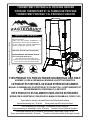
THIS PRODUCT IS FOR OUTDOOR HOUSEHOLD USE ONLY.
ASSEMBLY, CARE & USE MANUAL WARNING & SAFETY INFORMATION
CE PRODUIT EST DESTINÉ À UN USAGE EXTÉRIEUR SEULEMENT.
MANUEL D’ASSEMBLAGE, D’ENTRETIEN ET D’UTILISATTION – AVERTISSEMENTS ET
RENSEIGNEMENTS CONCERNANT LA SÉCURITÉ
ESTE PRODUCTO ES SOLAMENTE PARA USO EN EXTERIORES.
INFORMACIÓN DE ADVERTENCIAS Y SEGURIDAD DEL MANUAL DE ENSAMBLAJE, CUIDADO Y USO
Tools needed for assembly: Adjustable Wrench and Phillips Head Screwdriver
Approximate assembly time: 35 minutes *Actual product may diff er from picture shown
Outils nécessaires pour l’assemblage : clé ajustable et tournevis cruciforme
Temps nécessaire pour l’assemblage : environ 35 minutes * Le produit réel peut diff érer de l’illustration
Herramientas requeridas para el ensamblaje: Llave ajustable y destornillador Phillips o en cruz
Tiempo aproximado de ensamblaje: 35 minutos *El producto real puede ser distinto de la imagen mostrada
IMPORTANT! / IMPORTANTE !
Please record this information immediately and keep in a
safe place for future use.
Veuillez noter cette information immédiatement et la
conserver dans un endroit sûr pour une utilisation future.
Por favor, registrar esta información inmediatamente y
guardar en un lugar seguro para su uso futuro.
_________________________________________
Model number / Numéro de modèle / Número de modelo
_________________________________________
Mfg. Date - Serial Number / Date de fabrication - Numéro de
série / Fecha Fabricado - Número de serie
These numbers are located on the rating label of the unit.
Le numéro de série se trouve sur la plaque signalétique de l’appareil .
El número de serie se encuentra en la etiqueta de la unidad.
Manual Code: 9805160024 170208-GB
THERMOTEMP PROPANE & XL PROPANE SMOKER
PROPANE THERMOTEMP ET XL FUMEUR DE PROPANE
THERMOTEMP PROPANO Y XL PROPANO FUMADOR

2
Failure to follow these instructions could result in fi re, explosion or burn hazard
which could cause property damage, personal injury, or death.
Burning wood chips gives off carbon monoxide,
which has no odor and can cause death.
DO NOT burn wood chips inside homes,
vehicles, tents,
garages or any enclosed areas.
USE ONLY OUTDOORS where it is well
ventilated.
1. Never operate this appliance unattended.
2. Never operate this appliance within 10 feet (3.0m) of any structure, combustible material
or other gas cylinder.
3. Never operate this appliance within 25 feet (7.5m) of any fl ammable liquid.
4. If fi re should occur, keep away from appliance and immediately call your fi re department.
Do not attempt to extinguish an oil/grease fi re with water.
DANGER
CARBON MONOXIDE
HAZARD
DANGER
IF YOU SMELL GAS:
1. Shut off gas to the appliance.
2. Extinguish any open fl ame.
3. Open/remove door.
4. If odor continues, keep away from the
appliance and immediately call your Fire
Department.
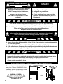
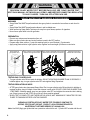
STRUCTURAL PROXIMITY AND SAFETY USAGE RECOMMENDATIONS
Before using smoker check wind direction
and place cylinder DOWNWIND. This is
necessary so that cylinder supply system
is arranged for vapor withdrawal.
Rails
Walls
10 Feet
10 Feet
Overhead Construction
This manual contains important information necessary for the proper assembly
and safe use of the appliance.
Read and follow all warnings and instructions before assembling and using the appliance.
Follow all warnings and instructions when using the appliance.
Keep this manual for future reference.
WARNING
CALIFORNIA PROPOSITION 65
1. Combustion by-products produced when using this product contain chemicals known to the
State of California to cause cancer, birth defects, and other reproductive harm.
2. This product contains chemicals known to the State of California to cause cancer, birth
defects or other reproductive harm.
WARNING
WARNING: HOSE IS A
TRIP HAZARD THAT
COULD CAUSE SUPPLY
CYLINDER TO TIP
GS30_40G1M 161011GB
Wind Flow

3
GENERAL WARNINGS AND SAFETY INFORMATION
• Always use unit in accordance with all applicable local, state and federal fi re codes.
• Before each use check all nuts, screws and bolts to make sure they are tight and secure.
• Never operate unit under overhead construction such as roof coverings, carports, awnings, or overhangs.
• Unit is for OUTDOOR USE ONLY.
• Never use inside enclosed areas such as patios, garages, buildings or tents.
• Never use inside or on recreational vehicles or boats.
• Maintain a minimum distance of 10ft (3m) from overhead construction, walls, rails or other structures.
• Keep a minimum 10ft (3m) clearance of all combustible materials such as wood, dry plants, grass, brush,
paper, or canvas.
• Never use unit for anything other than its intended use. This unit is NOT for commercial use.
• Accessory attachments not supplied by Masterbuilt Manufacturing, LLC are NOT recommended and may
cause injury.
• Use of alcohol, prescription or non-prescription drugs may impair user’s ability to properly assemble or
safely operate unit.
• Keep a fi re extinguisher accessible at all times while operating unit.
• When cooking with oil or grease, have a type BC or ABC fi re extinguisher readily available.
• In the event of an oil or grease fi re do not attempt to extinguish with water. Immediately call the fi re
department. A Type BC or ABC fi re extinguisher may, in some circumstances contain the fi re.
• Use unit on a level, non-combustible, stable surface such as dirt, concrete, brick or rock. An asphalt
surface (blacktop) may not be acceptable for this purpose.
• Unit MUST be on the ground. Do not place unit on tables or counters. Do NOT move unit across uneven
surfaces.
• Do not use unit on wooden or fl ammable surfaces.
• Keep unit clear and free from combustible materials such as gasoline and other fl ammable vapors and
liquids.
• Do not leave unit unattended.
• Keep children and pets away from unit at all times. Do NOT allow children to use unit. Close supervision is
necessary should children or pets be in area where unit is being used.
• Do NOT allow anyone to conduct activities around unit during or following its use until it has cooled.
• Never use glass, plastic or ceramic cookware in unit. Never place empty cookware in unit while in use.
• Never move unit when in use. Allow unit to cool completely (below 115°F (45°C)) before moving or storing.
• Store only when fi re is completely out and all surfaces are cold.
• Never use unit as a heater (READ CARBON MONOXIDE HAZARD).
• The unit is HOT while in use and will remain HOT for a period of time afterwards and during cooling
process. Use CAUTION. Wear protective gloves/mitts.
• Be careful when removing food from unit. All surfaces are HOT and may cause burns. Use protective
gloves/mitts or long, sturdy cooking tools for protection from hot surfaces or splatter from cooking
liquids.
• DO NOT bump or impact the unit to prevent personal harm, damage to unit or spillage/splashing of hot
cooking liquid.
• Do not touch HOT surfaces
• Unit is hot during use. To avoid burns, keep face and body away from door, lid and vents. Steam and hot
air are expelled during use.
• Air dampers are HOT while the unit is in use and during cooling; wear protective gloves when adjusting.
• Unit has an open fl ame. Keep hands, hair, and face away from burner fl ame. Do NOT lean over burner
when lighting. Loose hair and clothing may catch fi re.
• DO NOT obstruct fl ow of combustion and ventilation.
• Do not cover cooking racks with metal foil. This will trap heat and may cause damage to the unit.
• Installation of unit must conform with local codes or in the absence of local codes, with National Fuel Gas
Code, ANSIZ223.1/NFPA 54, Storage and Handling of Liquefi ed Petroleum Gasses, ANSI/NFPA 58 or CSA
B149.1, Natural Gas Installation Code; Propane Storage and Handling, CSA B149.2; or the Standard for
Recreational Vehicles, ANSI A119.2/NFPA 1192; and Recreational Vehicle Code, CSA Z240 RV Series as
applicable.
• Before each use inspect gas hose for signs of damage.
• Keep fuel supply hose away from any heated surface.
READ ALL INSTRUCTIONS
WARNINGS & IMPORTANT SAFEGUARDS
CONTINUED ON PAGE 4

4
WARNINGS & IMPORTANT SAFEGUARDS
CONTINUED FROM PAGE 3
SAVE THESE INSTRUCTIONS
GENERAL WARNINGS AND SAFETY INFORMATION
• Keep fuel supply hose away from unit while in operation.
• Regulator and hose assembly supplied with unit MUST be used. For replacement parts, if needed, contact
Masterbuilt Customer Service at 1-800-489-1581.
• Use 20LB (9kgs) gas cylinder that has protective collar (cylinder not included with unit).
• Keep ventilation openings of cylinder enclosure free and clear of debris.
• LP gas cylinder being used must be constructed and marked in accordance with specifi cations for LP gas
cylinders of the US Department of Transportation (DOT) or the Standard for Cylinders, Spheres and Tubes
for the Transportation for Dangerous Goods, CAN/CSA-B339.
• Never use gas cylinder if there is evidence of dents, gouges, bulges, fi re damage, erosion, leakage,
excessive rust, or other forms of visible external damage. This may be hazardous and cylinder should be
taken to a liquid propane supplier to be checked.
• Never attach/disconnect gas cylinder, move or alter gas fi ttings when unit is in operation.
• Always disconnect gas cylinder from unit when not in use.
• Unit is designed to work with propane gas only. Only use gas cylinders marked propane with this unit.
• This product will NOT operate with natural gas.
• When use is complete, always, fi rst turn the smoker control knob OFF, then turn the gas cylinder valve OFF,
and fi nally disconnect the cylinder.
• Gas MUST be turned off at the supply cylinder when not in use.
• Cylinder MUST be stored outdoors, out of children’s reach and must NOT be stored in a building, garage, or
any other enclosed area.
• Do NOT store spare LP gas cylinder under or near unit. Gas cylinder safety relief valve may overheat
allowing gas to release causing fi re which may cause death or serious injury.
• Never fi ll cylinder over 80% full or cylinder may release gas causing fi re which may cause death or serious
injury.
• Place a dust cap on cylinder valve outlet whenever cylinder is not in use. Only install dust cap provided with
cylinder. Other caps or plugs may cause leaks.
• If you smell, hear or see gas escaping, immediately get away from gas cylinder and call the Fire Department.
Fire may cause death or serious injury.
• Reference ignition steps before use.
• Never use lighter fl uid with propane.
• Wood chips must be used in order to produce smoke and create the smoke fl avor.
• Flame disk bowl/ wood chip tray/bowl is HOT when unit is in use. Use caution when adding wood.
• Check grease tray often during cooking. Empty grease tray before it gets full. Grease tray may need to be
emptied periodically during cooking.
• Do not open upper smoker door(s) unless necessary. Opening smoker door(s) causes heat to escape, which
may cause extended cooking time and may cause wood to fl are up. Closing the door(s) will re-stabilize the
temperature and stop fl are up.
• This is a smoker. There will be a lot of smoke produced when using wood chips. Smoke will escape through
seams and turn the inside of smoker black. This is normal. To minimize smoke loss around door(s), door
latch(s) can be adjusted to further tighten door seal against body.
• To adjust door handle/latch, loosen the two screws that mount the door hook to the smoker body. Slide the
door hook forward or rearward as needed to achieve the desired door seal. Then retighten the two door hook
screws. Be sure not to set the door handle/latch too tight as it could cause damage to the unit and make it
diffi cult to operate. The door should be adjusted so that it closes completely.
• When outside temperature is cooler than 65°F (18°C) and/or altitude is above 3,500 feet (1067m), additional
cooking time may be required. To insure that meat is completely cooked use a meat thermometer to test
internal temperature.
• Do not use wood pellets.
• Food needs to be in the center of smoking racks. This allows food drippings to go into the water bowl.
• Do not leave old wood or ashes in the fl ame disk bowl/woodchip tray/bowl. Once ashes are cold, empty
bowl/tray. Bowl/tray should be cleaned out prior to, and after each use to prevent ash and residue buildup.
• Dispose of cold ashes by placing them in aluminum foil, soaking with water and discarding in a non-
combustible container.
• Do not store unit with HOT ashes inside unit.

5
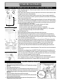
GETTING STARTED
• Pre-season unit prior to fi rst use. See PRE-SEASON INSTRUCTIONS.
• Before starting the unit, see ADDING WOOD CHIPS.
• This smoker is equipped with door stops that will hold the door open during loading and unloading of food.
• Food amount or volume and ambient temperature may aff ect smoker temperature. Make adjustments as necessary to achieve desired
smoking temperature.
CAUTION - All surfaces are HOT and may cause burns. Use protective gloves or long, sturdy cooking tools when loading/
unloading food or racks, and when adding wood chips or water.
PRE
-
SEASON INSTRUCTIONS
Curing your smoker will rid the unit of chemicals and oils left over by the manufacturing process allowing them to burn off .
PRE-SEASON SMOKER PRIOR TO FIRST USE.
1. Perform soapy water test, see SOAPY WATER TEST WARNINGS AND PROCEDURES.
2. Using a napkin or cloth, rub a light coat of cooking oil on smoking racks and inside smoker door. Make sure water pan is in place with
NO WATER.
3. Fill wood chip tray with up to 1 cup (0.24l) of wood chips and light smoker. Close door.
4. Start smoker, set to 350°F (177°C) and let the smoker burn for about 1 hour.
5. Allow unit to cool COMPLETELY.
6. Reapply light coat of cooking oil on smoking racks and inside of smoker door.
7. Restart smoker and burn for 20 minutes.
• Cure your smoker periodically to prevent excessive rust.
ADDING WOOD CHIPS
1. You may use dry or pre-soaked wood chips in your smoker. Dry chips will burn faster and produce more intense smoke. Chips pre-
soaked in water (for approximately 30 minutes) will burn slower and produce a less intense smoke.
2. Before starting unit, place up to 1 cup (0.24l) of wood chips in wood chip tray.
3. DO NOT ADD MORE THAN 1 CUP (0.24l) OF WOOD CHIPS AT A TIME. Never use wood chunks or wood pellets.
4. Place additional wood chips in smoker as needed to achieve desired smoke fl avor.
• Wood chips must be used in order to produce smoke and create the smoke fl avor.
OPERATING INSTRUCTIONS
1. To start smoker see IGNITION INSTRUCTIONS.
2. With protective gloves on, place water bowl in position. Pour 1 inch of water, juice, or vinegar into water bowl. This will add fl avor and
moisture to food and prevent it from drying out.
3 DO NOT cover racks with aluminum foil as this will not allow heat to circulate properly.
4. Pre-heat smoker to desired temperature for approximately 20 minutes.
5. Place food in the smoker, position on the center of the smoking rack.
6 DO NOT overload smoker with food. Extra large amounts of food may trap heat, extend cooking time and cause uneven cooking. Leave
space between food on racks and smoker sides to ensure proper heat circulation. If utilizing cooking pans, place pans on center of rack
to ensure even cooking.
7. For best results, rotate racks between the top and bottom positions during cooking.
8. Adjust smoker settings, control knob and air damper, to desired cooking temperature.
• Close air damper on unit to retain moisture and heat. If cooking foods such as fi sh or jerky, open air damper to release moisture.
9. If wood chips do not smoke on low setting, open bottom door slightly for approximately 2 minutes. This will allow the cabinet
temperature to fall which will cause the burner to adjust to a larger fl ame and will begin the smoking process.
10. Use caution when cooking on windy days to ensure the fl ame does not blow out. If you suspect or experience a fl ame blow out, fi rst
open the door to check the fl ame and follow the IGNITION INSTRUCTIONS to re-ignite the burner if needed. Adjust the smoker control
knob setting for a higher fl ame to prevent further blow outs.
Never ignite smoker with the door closed.
11. Extreme cold temperatures may extend cooking times.
12. Once cooking is complete turn unit OFF, see IGNITION INSTRUCTIONS for turning off unit, remove the gas cylinder and then follow
CLEANING and STORING INSTRUCTIONS. CLEAN AFTER EVERY USE. This will extend the life of your smoker and prevent mold
and mildew.
OPERATING TIP - When changing the temperature from a higher temperature setting to a lower temperature setting allow the
unit to stabilize between temperature changes for 5 minutes before opening and closing the door(s). During this transition period
the fl ame is vulnerable to potential blow outs, under certain conditions, because the pressure inside the burner is reduced while
the temperature sensor is adjusting to the lower temperature. For example, changing from 275
°F (135°C)
down to 225
°F (107°C)
.
CLEANING and STORING INSTRUCTIONS
• ALWAYS MAKE SURE UNIT IS COOL TO THE TOUCH BEFORE CLEANING AND STORING.
• Be sure to clean smoker after each use. Make sure the gas cylinder has been turned off and removed.
• For rack supports, racks, water bowl, and drip pan use a mild dish detergent. Rinse and dry thoroughly.
• For woodchip tray clean frequently to remove ash build up, residue and dust.
• Dispose of cold ashes by placing them in aluminum foil, soaking with water and discarding in a non-combustible container.
• For the interior, exterior and door seal of the unit simply wipe down with a damp cloth after each use to keep unit in proper working
condition. Do not use a cleaning agent. Make sure to dry thoroughly.
• After cleaning, store smoker in a covered and DRY AREA.
• Store only when fi re is completely out and all surfaces are cold.
• When not in frequent use and using a cover, remember to check your smoker periodically to avoid possible rust and corrosion due to
moisture buildup.
CHECK OUT THE MASTERBUILT WEBSITE FOR MORE TIPS AND RECIPE VIDEOS.
SMOKER OPERATION - READ & FOLLOW ALL INSTRUCTIONS CAREFULLY

6
Apply solution to
gas cylinder valve
Failed test will present
bubbles as shown below.
Apply solution underneath control panel
where burner and hose are connected
WARNING
SOAPY WATER TEST WARNINGS & PROCEDURES
WARNINGS
• Soapy Water Test MUST be performed each time gas cylinder is connected to burner/hose or each time it is
used.
• Soapy Water Test MUST be performed outdoors in well ventilated area.
• When performing Soapy Water Test keep unit away from open fl ames, sparks or lit cigarettes.
• Never use an open fl ame to test for gas leaks.
PREPARATION:
• Remove any cookware and accessories from unit.
• Make sure gas cylinder valve and control knob are turned to the OFF position.
• Prepare soapy water solution: (1) part dish washing liquid (or more if desired), (3) parts water.
• Apply soapy water solution to gas cylinder valve, regulator and hose length up to burner control valve.
PERFORM “SOAPY WATER TEST” BEFORE EACH USE. SEE “SOAPY WATER TEST”
SECTION IN MANUAL.
EXTINGUISH ALL OPEN FLAMES BEFORE CONNECTING REGULATOR
TO GAS CYLINDER. TURN GAS OFF AFTER EACH USE.
TESTING GAS CYLINDER VALVE:
• Turn gas cylinder valve ON and watch for bubbles. DO NOT LEAVE GAS ON MORE THAN 12 SECONDS. If
bubbles appear, stop, turn gas cylinder valve OFF and retighten fi tting. Repeat test.
TESTING REGULATOR AND HOSE:
• AFTER gas cylinder valve has passed Soapy Water Test, turn gas cylinder valve ON and check for bubbles at
regulator location, along full length of hose and at burner control valve. DO NOT LEAVE GAS ON MORE THAN
12 SECONDS. If bubbles appear, stop, turn gas cylinder valve OFF and retighten the connection that is leaking
gas. If hose is source of leak, STOP, do not use unit. Hose must be replaced.
• WHEN TEST IS COMPLETE, AND THERE ARE NO LEAKS, WAIT MINIMUM OF 5 MINUTES FOR GAS
FUMES TO DIMINISH BEFORE LIGHTING SMOKER.
DURING ANY PORTION OF SOAPY WATER TEST IF BUBBLES CONTINUE TO
APPEAR, STOP, DO NOT USE UNIT. CONTACT LOCAL PROPANE DEALER OR
MASTERBUILT CUSTOMER SERVICE AT 1-800-489-1581.
Note: Use 20LB (9kgs) gas cylinder that has a protective collar with this unit. Cylinder NOT included with this unit.
Apply solution to hose regulator
and the full length of the hose

7
REGULATOR, BURNER AND GAS VALVE CONNECTION & OPERATION
IGNITION INSTRUCTIONS
CLOCKWISECLOCKWISE
COUNTER
CLOCKWISE
17.75”
(45cm)
APPROX.
12.25” (45cm)
APPROX.
Fig. 3
Fig. 1
MATCH LIGHT INSTRUCTIONS
1. Read all instructions and warnings before lighting.
2. Check control knob and gas cylinder valve to be certain it is in OFF position before connecting to
gas cylinder.
3. Perform soapy water test before each use.
4. Open door(s) during lighting and/or remove all accessories and cooking vessels from in/or on unit.
5. Turn gas cylinder valve ON, push control knob in, hold and and turn counter-clockwise to desired
temperature setting, after ignition continue holding control knob in for 5 seconds to activate the
fl ame sensor.
6. Place a long, lit fi replace match stick close enough to burner to ignite.
7. If ignition does not take place within fi ve seconds, turn control knob to OFF position and wait fi ve
minutes and repeat match light instructions.
8. After each use, fi rst turn control knob off , then gas cylinder valve off . Always allow unit to cool
completely before touching, moving or storing.
• Inspect hose before each use. If there are signs of abrasion, wear, cuts, or leaks, the hose must be
replaced. DO NOT USE.
• Inspect burner before each use. Check burner and burner venturi tube for insects and insect nests.
A clogged tube can lead to a fi re beneath unit.
• Check to ensure the orifi ce is centered inside the venturi tube. Failure to properly assemble the
valve orifi ce to the venture tube can result in gas leak or potential fi re at connection. See assembly
steps for proper assembly method.
• Check to ensure the igniter pin is properly spaced and aligned to the burner. Igniter pin should be
approximately 1/4” from the burner and aligned to the top of a burner port (Fig. 2). Confi rm spacing
is correct by pressing the igniter button and ensuring spark occurs between igniter pin and burner.
• Connect hose regulator to LP Gas Cylinder
1. Make sure gas cylinder valve is closed. Turn valve clockwise until it stops.
2. Make sure control knob on smoker is in the OFF position.
3. Remove protective cap from gas cylinder and coupling nut if applicable.
4. Center and insert regulator nipple into valve outlet on gas cylinder (Fig. 1). Turn regulator
coupling nut clockwise until it stops. DO NOT OVER TIGHTEN.
• Perform Soapy Water Test.
• Before starting lighting procedure make sure the smoker door(s) are open.
• When lighting burner remove all parts inside or on unit to prevent explosion from gas build up.
• To use, turn gas cylinder valve ON, push control knob in, hold and and turn counter-clockwise to
desired temperature setting. Push ignitor button to light, after ignition continue holding control knob
in for 5 seconds to activate the fl ame sensor.
• If ignition does not take place within fi ve seconds, turn control knob to OFF position and wait fi ve
minutes and repeat lighting procedures. If ignition still does not occur, see match light instructions.
• Always ensure that smoker door(s) are open before igniting. Gas can accumulate in smoker.
• If fl ame goes out during cooking, turn control knob OFF, turn gas cylinder valve OFF, wait 5
minutes, then open door(s) and wait 5 additional minutes before repeating ignition instructions
above.
• Control knob sets the smoker to a desired temperature. Push control knob in and turn clockwise to
shut fl ame off .
• Visually check burner fl ame (Fig. 3). A CORRECT FLAME should be blue with a small amount of
yellow at the tip. An INCORRECT FLAME is excessively yellow and irregular. If an incorrect fl ame
occurs, turn control knob to OFF position, turn OFF gas cylinder valve, allow unit to cool and then
clean burner. Let burner completely dry before re-lighting.
• After use turn control knob OFF, then turn gas cylinder valve OFF and disconnect tank.
• Type 1 Regulators will have a hook (Fig. 4). The Regulator Hook is used to keep the regulator off
the ground when removed from the LP cylinder. Attach to unit as shown in image.
Fig.4
1/4"
Fig. 2

8
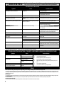
TROUBLESHOOTING GUIDE
Symptom Cause Possible Solution
Gas leaking from cracked, cut or burned hose Damaged hose Turn off gas at LP cylinder.
Replace hose.
Contact Masterbuilt at 1.800.489.1581.
Gas leaking from LP cylinder Failure due to rust or mishandled equipment Replace LP cylinder.
Gas leaking from gas cylinder valve Failure of valve due to rust, mechanical failure or mishandled
equipment
Turn off gas cylinder valve and return cylinder to gas provider/supplier.
Gas leaking between LP cylinder and regulator connection Improper installation, connection not tight enough, damaged
threads or bad rubber seal
Turn off gas cylinder valve, then re-attach regulator to cylinder.
Turn off gas cylinder valve and return cylinder to gas provider/supplier.
Visually inspect rubber seal for damage.
Fire under control panel Fire in tube of burner due to burner blockage Turn off both smoker control knob and gas cylinder valve. Once the fi re is
out and burner has cooled, remove and inspect burner for spiders, nests,
rust or other debris.
Grease fi re or excessive/continuous fl ame Grease build up on or around burner area Turn off both smoker control knob and gas cylinder valve. Allow fl ames
to extinguish and time for unit to cool down. Clean grease/food particles
from/around burner or burner area and surrounding surfaces.
Flame does not remain lit after igniting* Flame sensor wire is loose Turn off gas. Disconnect LP cylinder. Tighten fl ame sensor wire to valve.
Low fl ame output* Out of fuel Refi ll or replace with full LP cylinder.
Flames blow out* Low on LP gas Refi ll LP cylinder.
Flare-up Excessive grease buildup Clean burner and inside unit.
Excessive fat on meat Trim fat off of meat.
Cooking temperature too high Adjust or lower temperature accordingly.
Persistent grease fi re Grease trapped by food buildup around burner system Turn smoker control knob and gas cylinder valve off . Allow fi re to
extinguish and the unit to cool down. Once cool, remove and clean parts.
Flashback (fi re in burner tube) Burner and/or burner tube has blockage Turn smoker control knob and gas cylinder valve off . Clean burner and/
or burner tube.
Slower than expected cooking times* Valve not properly aligned to burner Check to see if valve is centered in burner tube.
WARNING
In the event of a gas leak that cannot be stopped, or if a
fi re occurs due to a gas leak, contact the fi re department.
TROUBLESHOOTING SOLUTIONS: “CAUSES” LOW OR NO FLOW/VAPOR LOCK/EXCESS FLOW
Symptom Cause Possible Solution
Burner doesn’t light after pressing ignitor button Low/no gas fl ow 1. Turn smoker control knob to “Off ” position.
2. Turn gas cylinder valve knob to OFF.
3. Disconnect regulator from cylinder to relieve vapor lock.
4. Reconnect regulator to cylinder by hand turning until tight.
5. Slightly open the gas cylinder valve slowly and then open further by turning 1 full
turn.
6. You are now ready to light the smoker.
7. Turn the smoker control knob to high and light with ignitor.
Vapor lock at coupling nut to LP cylinder
Low fl ame output Excess fl ow valve tripped
Vapor lock at coupling nut/LP cylinder
connection
Flames blow out Excess fl ow valve tripped
Slower than expected cooking times Vapor lock
*
Also seeTroubleshooting solutions: “Causes” Low or No Flow/Vapor lock/Excess fl ow below.
FAQ
• Was the temperature setting of the unit adjusted from a higher setting to a lower setting? For example, was the unit at 275 and changed to 225?
If yes, was the unit allowed to stabilize for 5 minutes at the new temperature setting before opening/closing the door(s)? If no, allow the unit to stabilize between set point changes for 5 minutes before opening
and closing the door(s). During this transition period the fl ame is vulnurable to potential blow outs, under certain conditions, because the pressure inside the burner is reduced while the temperature sensor is
adjusting to the lower set point.
• Is the vent open?
If no, open the vent to allow more heat to exit the unit. This will cause the unit to require more heat input to maintain its set point which will cause the unit to increase the fl ame height creating a stronger fl ame.
• Is the water bowl fi lled?
If no, fi ll the water bowl. This will cause the unit to require more heat input to maintain its set point which will cause the unit to increase the fl ame height creating a stronger fl ame.
• Is outside wind greater than 5mph?
If yes, and all the above solutions did not improve the performance, raise the set point of the unit in order to cook in those conditions.

9
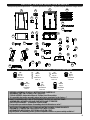
(C)
M4.2x8
Qty-15
Quantité-15
Cant.-15
PARTS LIST, LISTE DES PIÈCES, LISTA DE PARTES
HARDWARE LIST, LISTE DE MATÉRIEL, LISTA DE HARDWARE
• BEFORE ASSEMBLY READ ALL INSTRUCTIONS CAREFULLY.
• ASSEMBLE UNIT ON A CLEAN, FLAT SURFACE.
• TOOLS NEEDED: Adjustable Wrench, Phillips Head Screwdriver
** It is possible that some assembly steps have been completed in the factory. **
• AVANT L’ASSEMBLAGE, LIRE ATTENTIVEMENT TOUTES LES INSTRUCTIONS.
• ASSEMBLER L’APPAREIL SUR UNE SURFACE PLANE ET PROPRE.
• OUTILS NÉCESSAIRES : TOURNEVIS CRUCIFORME.
**Il est possible que certaines étapes d’assemblage aient été eff ectuées en usine.**
• ANTES DEL ENSAMBLAJE LEA TODAS LAS INSTRUCCIONES CUIDADOSAMENTE.
• ENSAMBLE LA UNIDAD EN UNA SUPERFICIE LIMPIA Y PLANA.
• HERRAMIENTA NECESARIA: DESTORNILLADOR EN CRUZ.
**Algunos pasos del ensamblaje pueden ya estar completados debido a un preens amblaje en fábrica.**
Actual product may diff er from picture shown
Le produit réel peut diff érer de l’illustration
El producto real puede ser distinto de la imagen mostrada
(A)
M6x12
Qty-45
Quantité-45
Cant.-45
(D)
M4x8
Qty-6
Quantité-6
Cant.-6
(B)
M5x10
Qty-4
Quantité-4
Cant.-4
(G)
M5x10
Qty-2
Quantité-2
Cant.-2
(E)
M6 Lock
Qty-1
Quantité-1
Cant.-1
(F)
M6
Qty-22
Quantité-22
Cant.-22
1
2
3
6
7
8
9
18
12
11
10
13
28
27
14
15
16
22
19
21
5
4
29
30
31
32
33
36
34
35
24
26
25
23
20
37
17

10
PARTS LIST, LISTE DES PIÈCES, LISTA DE PARTES
NO/Nº/NO QTY/QTÉ./CANT. DESCRIPTION DESCRIPTION DESCRIPCIÓN
1 1 Air Damper Clapet d’aération Regulador de aire
2 1 Top Smoker Body Top fumeur de corps Cuerpo superior Fumador
3 1 Top Smoker Door Porte fumeur Top Puerta superior fumador
4 1 Bottom Smoker Body Corps de fumeur en bas Parte inferior del ahumador
5 1 Bottom Smoker Door Porte fumeur fond La puerta del ahumador inferior
6 1 Top Cabinet Temperature Sensor Cover Armoire supérieure couvercle du capteur de
température
Cubierta del sensor de temperatura superior del gabinete
7 1 Bottom Cabinet Temperature Sensor Cover Armoire inférieure couvercle du capteur de
température
Cubierta del sensor de temperatura del fondo del
gabinete
8 1 Top Door Handle Poignée de porte Top Manija de la puerta superior
9 1 Bottom Door Handle Poignée de porte en bas Manija de la puerta inferior
10 4 Smoking Rack Étagère fumeurs Estante de fumadores
11 1 Water Bowl Rack Support du réservoir d’eau Sostenedor de la bandeja de agua
12 1 Water Bowl Réservoir d’eau Bandeja de agua
13 1 Tank Retainer Bracket Réservoir de retenue Bracket El tanque de retención del soporte
14 1 Tank Support Support de réservoir Soporte de la cisterna
15 1 Match Stick w/Chain Allumette avec chaîne Palillo de fósforo con cadena
16 1 Control Knob Bouton de commande Perilla de control
17 1 Ignitor Ignitor Ignitor
18 1 Cabinet Temperature Sensor Bracket Cabinet du capteur de température Support Gabinete soporte del sensor de temperatura
19 1 Control Panel Panneau de commande Panel de control
20 1 Cabinet Temperature Sensor Cabinet du capteur de température Sensor de temperatura del armario
21 1 Valve Assembly Assemblée Valve Conjunto de válvula
22 1 Heat Diff user Diff useur Difusor de calor
23 1 Burner Box Kit Ensemble bac à combustion Kit de la caja del quemador
24 1 Heat Shield Écran thermique Protector contra el calor
25 1 Grease Tray Bracket Support du collecteur de graisse Soporte de la bandeja de grasa
26 1 Grease Tray Collecteur de graisse Bandeja de grasa
27 1 Wood Chip Tray Rack Claie de copeaux de bois Estante de la bandeja para astillas de madera
28 1 Wood Chip Tray w/Lid Bac à copeaux de bois avec couvercle Bandeja de astillas de madera con tapa
29 1 Right Front Leg Droite Jambe Avant Frente de la pierna derecha
30 1 Left Front Leg Jambe avant gauche Pierna izquierda Frente
31 1 Right Rear Leg Patte arrière droite Pata trasera derecha
32 1 Left Rear Leg Jambe arrière gauche Pata trasera izquierda
33 1 Rear Leg Brace Arrière attelle Paréntesis de la pierna trasera
34 1 Left Side Leg Brace Jambe renfort latéral gauche Abrazadera del lado izquierdo de la pierna
35 1 Right Side Leg Brace Jambe accolade côté droit Lado derecho pierna ortopédica
36 1 Tank Leg Brace Réservoir d’ attelle jambe Refuerzo de las patas del tanque
37 1 Gas Manifold Bracket Support de collecteur de gaz Soporte de colector de gas
WARNING, AVERTISSEMENT!, ¡ADVERTENCIA!
• Smoker should only
be rolled on smooth
surface.
• Ne faire rouler le
fumoir que sur
une surface
lisse.
• El ahumador solo
debe empujarse sobre
una superfi cie lisa.
• Potential damage to smoker or harm to user may result from failure to follow warnings.
• Smoker should never be
rolled up/down stairs or
uneven surface.
• Ne jamais faire rouler le
fumoir dans des escaliers ou
sur une surface inégale.
• El ahumador nunca debe
empujarse escaleras arriba/
abajo o sobre superfi cies
desiguales.
• Si les avertissements ne sont pas respectés, des dommages au fumoir ou des blessures à l’utilisateur pourraient s’ensuivre.
• El daño potencial al ahumador o daño a algún usuario pueden ser el resultado de no seguir las advertencias.

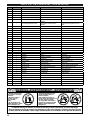
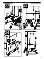
11
ASSEMBLY, ASSEMBLAGE, ENSAMBLAJE
Actual product may diff er from picture shown
Le produit réel peut diff érer de l’illustration
El producto real puede ser distinto de la imagen mostrada
A
x4
23
4
3
2
1
AA
2
3
C
C
x7
4
2
A
A
A
F
x2 x2
4
F
F
14
36

12
A F
x18 x16
A
x12
5
ASSEMBLY, ASSEMBLAGE, ENSAMBLAJE
6
31
34
36
33
35
29
30
32
A
A
FRONT
AVANT
FRENTE
FRONT
AVANT
FRENTE
A
A
A A
A
A
A
F
F
F
F
A
A
A
A
A
F
F
Do not tighten all screws yet
Ne serrez pas encore toutes les vis
No apriete todos los tornillos
Tighten all screws
Serrer toutes les vis
Apriete todos los tornillos
Swivel Casters
Roulettes pivotantes
Ruedas giratorias
Swivel Casters
Roulettes pivotantes
Ruedas giratorias

13
D
D
19
21
37
17
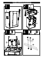
ASSEMBLY, ASSEMBLAGE, ENSAMBLAJE
7
D
x4
9
Hole for
Cabinet
Temperature
Sensor
A
A
F
F
FA
x4x4
Venturi / Tube de Venturi / Venturi
Valve Orifi ce / Orifi ce du robinet / Orifi cios de la válvula
Piezo Ignitor / Dispositif d’allumage venturi / Arrancador piezoeléctrico
Ignition Wire / Fils du dispositif d’allumage / Alambres de ignición
Flame Sensor Wire / Fil de capteur de fl amme / Cable del sensor de llama
Cabinet Temperature Sensor Wire / armoire fi l de capteur de température / cable del
sensor de temperatura del gabinete
19
8
Valve
Orifi ce
Piezo
Ignitor
Venturi
Ignition Wire
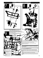
Carefully uncoil the cabinet temperature sensor wire and locate the hole at the back of the smoker body
(shown here). USE EXTREME CARE NOT TO CRIMP OR BREAK THE CABINET TEMPERATURE
SENSOR WIRE (oil fi lled).
Dévisser soigneusement le fi l du capteur de température de l'armoire et localiser le trou à l'arrière du corps
du fumeur (illustré ici). UTILISEZ UN TRAITEMENT EXTRÊME POUR NE PAS SERTIR NI DÉBARRER
LE FIL DU CAPTEUR DE TEMPÉRATURE (rempli d'huile).
Desenrolle cuidadosamente el cable del sensor de temperatura del gabinete y localice el agujero en
la parte posterior del cuerpo del fumador (mostrado aquí). UTILICE UN EXTREMO CUIDADO PARA
NO PIRAR O ROMPER EL ALAMBRE DEL SENSOR DE TEMPERATURA DEL GABINETE (lleno de
aceite).
Align venturi over valve orifi ces and attach ignition wire to piezo ignitor on control panel.
En alignant soigneusement le tube de Venturi aux orifi ces du robinet et en fi xant solidement les
fi ls d’allumage au dispositif d’allumage piézo sur le panneau de contrôle.
Alinear venturi más orifi cios de la válvula y una el cable de encendido a encendedor
piezoeléctrico en el panel de control.
Ignition Wire
CAUTION: Over bending the cabinet temperature sensor wire could result in damage.
ATTENTION: Au cours de la fl exion de l'armoire température fi l du capteur pourrait entraîner une rupture.
PRECAUCIÓN: Durante la fl exión del cable del sensor de temperatura del gabinete podría producirse una
ruptura.
Cabinet
Temperature
Sensor Wire
Carefully attach the fl ame sensor wire to the
valve as shown. Ensure fully tightened.
Fixez soigneusement le fi l du détecteur de
fl amme à la vanne comme indiqué. Assurez-
vous qu'il est bien serré.
Conecte cuidadosamente el cable del sensor
de llama a la válvula como se muestra.
Asegúrese de que esté completamente
apretado.
Flame
Sensor Wire
Cabinet
Temperature
Sensor Wire

14
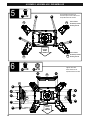
ASSEMBLY, ASSEMBLAGE, ENSAMBLAJE
11
10
18
20
20
C
x2
12
18
C
C
6
2
4
7
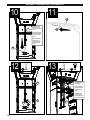
Place cabinet temperature
sensor wire behind the cover
before installing it.
Placez cabinet capteur de
température fi l derrière les
couvertures avant de les
installer.
Coloque el alambre del
sensor de temperatura
del gabinete detrás de las
cubiertas antes de instalarlas.
Carefully thread cabinet
temperature sensor wire
down through the body of the
smoker.
Enfi ler soigneusement le fi l
du capteur de température
de l'armoire dans le corps
du fumeur
Atornille cuidadosamente
el cable del sensor de
temperatura del gabinete
a través del cuerpo del
fumador.
D
C
C
13
C
x6
D
x2

15
Turn smoker over onto legs
Retournez le fumeur sur les jambes
Convierte al fumador en las piernas
ASSEMBLY, ASSEMBLAGE, ENSAMBLAJE
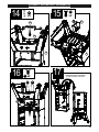
16
17
B
24
23
4
B
B
x4
14 15
G
x2
4
A
x4
22
AA
16
25
G

16
10
12
11
4
2
2120
3
5
1
E
EA
x1x1
A
18
ASSEMBLY, ASSEMBLAGE, ENSAMBLAJE
19

17
28
5
27
26
23
24
22
13
15
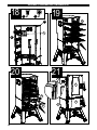
ASSEMBLY, ASSEMBLAGE, ENSAMBLAJE
Assembly is complete
L'assemblage est terminé
La asamblea está completa

18
DO NOT RETURN TO RETAILER for assembly assistance, missing or damaged parts.
Please contact MASTERBUILT customer service at 1-800-489-1581 or support.masterbuilt.com. Please have the model number
and serial number available. These numbers are located on the silver rating label on the unit.
NNE PAS RETOURNER AU DÉTAILLANT pour l'assistance d'assemblage, pièces manquantes ou endommagées. S'il vous plaît
contacter le service à la clientèle au 1-800-489-1581 ou MASTERBUILT
support.masterbuilt.com
. S'il vous plaît avoir le numéro de
modèle et le numéro de série. Ces numéros se trouvent sur la plaque signalétique de l'argent sur l'unité.
NO REGRESE A DISTRIBUIDOR para ayuda con el montaje, partes faltantes o dañados. Por favor, póngase en
contacto con el servicio al cliente al 1-800-489-1581 o MASTERBUILT support.masterbuilt.com. Tenga a mano los
números de modelo y número de serie. Estos números se encuentran en la placa de plata en la unidad.
STOP!
ARRÊTEZ!
¡ALTO!
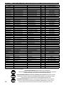
Replacement parts may vary by item number of model. Les pièces de rechange peuvent varier selon le numéro de l’article du modèle. Las piezas de repuesto
pueden variar según el número de artículo del modelo.
REPLACEMENT PARTS LIST, LISTE DES PIÈCES DE RECHANGE, LISTA DE PARTES DE REPUESTO
REPLACEMENT
PART
PIÈCE DE RECHANGE REPUESTO NO/Nº/NO
APPLIES TO ITEM/POUR ARTICLE/ SE
APLICA AL ARTÍCULO
Top Smoker Body Kit Ensemble fumoir Kit del cuerpo del ahumador 9905160008 20050716, 20050816, 20050916
Top Smoker Body Kit Ensemble fumoir Kit del cuerpo del ahumador 9905160038 20051316, 20051416
Bottom Smoker Body Kit Ensemble fumoir Kit del cuerpo del ahumador 9905160022 20050716, 20050816, 20050916
Bottom Smoker Body Kit Ensemble fumoir Kit del cuerpo del ahumador 9905160045 20051316, 20051416
Top Smoker Door Kit Ensemble porte principale du fumoir Kit de la puerta grande del ahumador 9905160013 20050716, 20050916
Top Smoker Door Kit Ensemble porte principale du fumoir Kit de la puerta grande del ahumador 9905160009 20050816
Top Smoker Door Kit Ensemble porte principale du fumoir Kit de la puerta grande del ahumador 9905160046 20051316, 20051416
Top Smoker Door Kit Ensemble porte principale du fumoir Kit de la puerta grande del ahumador 9905160013 20050916
Bottom Smoker Door Kit Ensemble porte principale du fumoir Kit de la puerta grande del ahumador 9905160032 20050716, 20050816, 20050916
Bottom Smoker Door Kit Ensemble porte principale du fumoir Kit de la puerta grande del ahumador 9905160047 20051316, 20051416
Door Handle Kit Ensemble poignée de porte principale Kit del asa de la puerta grande 9905160024 All models, Tous les modèles, Todos los modelos
Right Front Leg Kit Ensemble pied droit avant Kit de la pata frontal derecha 9905160010 20050716, 20050816, 20050916
Left Front Leg Kit Ensemble pied gauche avant Kit de la pata frontal izquierda 9905160011 20050716, 20050816, 20050916
Right Rear Leg Kit Ensemble pied droit arrière Kit de la pata posterior derecha 9905160012 20050716, 20050816, 20050916
Left Rear Leg Kit Ensemble pied gauche arrière Kit de la pata posterior izquierda 9905160036 20050716, 20050816, 20050916
Right Front Leg Kit Ensemble pied droit avant Kit de la pata frontal derecha 9905160048 20051316, 20051416
Left Front Leg Kit Ensemble pied gauche avant Kit de la pata frontal izquierda 9905160049 20051316, 20051416
Right Rear Leg Kit Ensemble pied droit arrière Kit de la pata posterior derecha 9905160050 20051316, 20051416
Left Rear Leg Kit Ensemble pied gauche arrière Kit de la pata posterior izquierda 9905160051 20051316, 20051416
Left Side Leg Brace Kit Ensemble support latéral de pied Kit de la abrazadera de la pata lateral 9905160014 20050716, 20050816, 20050916
Right Side Leg Brace Kit Ensemble support latéral de pied Kit de la abrazadera de la pata lateral 9905160023 20050716, 20050816, 20050916
Rear Leg Brace Kit Ensemble support arrière de pied Kit de la abrazadera de la pata posterior 9905160015 20050716, 20050816, 20050916
Left Side Leg Brace Kit Ensemble support latéral de pied Kit de la abrazadera de la pata lateral 9905160052 20051316, 20051416
Right Side Leg Brace Kit Ensemble support latéral de pied Kit de la abrazadera de la pata lateral 9905160053 20051316, 20051416
Rear Leg Brace Kit Ensemble support arrière de pied Kit de la abrazadera de la pata posterior 9905160054 20051316, 20051416
Control Panel and HVR Kit Ensemble panneau de commande Kit del panel de control 9905160025 20050716, 20050816, 20050916
Control Panel and HVR Kit Ensemble panneau de commande Kit del panel de control 9905160055 20051316, 20051416
Burner Box Kit Ensemble bac à combustion Kit de la caja del quemador 9905160026 20050716, 20050816, 20050916
Burner Box Kit Ensemble bac à combustion Kit de la caja del quemador 9905160057 20051316, 20051416
Air Damper Kit Clapet d’aération (carré) Regulador de aire (cuadrado) 9905140008 All models, Tous les modèles, Todos los modelos
Push Button Ignitor Kit Ensemble assemblage du dispositif d’allumage Kit de ensamblaje del arrancador 990060328 All models, Tous les modèles, Todos los modelos
Grease Tray Bracket Kit Ensemble collecteur de graisse Kit de la bandeja de grasa 9905160044 20050716, 20050816, 20050916
Grease Tray Bracket Kit Ensemble collecteur de graisse Kit de la bandeja de grasa 9905160056 20051316, 20051416
Tank Retainer Kit Ensemble support de rétention de bouteille de gaz Kit de la abrazadera de retención del tanque 9905160043 All models, Tous les modèles, Todos los modelos
Tank Leg Brace Kit Ensemble support de rétention de bouteille de gaz Kit de la abrazadera de retención del tanque 9905160031 All models, Tous les modèles, Todos los modelos
Tank Support Kit Ensemble support de réservoir Kit de soporte del tanque de 9903160002 All models, Tous les modèles, Todos los modelos
3" Wheel Kit Ensemble de 3" roues 3" Juego de Ruedas 9905160037 All models, Tous les modèles, Todos los modelos
Wood Chip Tray Kit Bac à copeaux de bois avec couvercle Bandeja de trozos de madera con tapa 9005160033 All models, Tous les modèles, Todos los modelos
Temp Sensor Bracket Kit Température kit de support de capteur Kit de soporte de sensor de temperatura 9905160034 All models, Tous les modèles, Todos los modelos
Control Knob Kit Bouton de contrôle Perilla de control 9905160042 All models, Tous les modèles, Todos los modelos
Heat Diff user Kit Ensemble de diff useur de chaleur Kit difusor de calor 9905160040 All models, Tous les modèles, Todos los modelos
3" Locking Swivel Caster 3" verrouillage roulette pivotante 3" de ruedecillas de bloqueo 9005160050 All models, Tous les modèles, Todos los modelos
Wood Chip Tray Rack Claie de copeaux de bois Estante de madera bandeja de fi chas 9005160021 All models, Tous les modèles, Todos los modelos
Grease Tray Collecteur de graisse Bandeja de grasa 9005100069 20050716, 20050816, 20050916
Grease Tray Collecteur de graisse Bandeja de grasa 9005140017 20051316, 20051416
Flame Sensor Détecteur de fl amme Sensor de llama 9005160069 All models, Tous les modèles, Todos los modelos
Smoking Rack Étagère fumeurs Estante de fumadores 910050029 20050716, 20050816, 20050916
Accessory Rack
Étagèree accessoires Estante accesorio
9007160171 20050916
Accessory Rack
Étagèree accessoires Estante accesorio
9007160172 20051416
Smoking Rack Étagère fumeurs Estante de fumadores 9007120012 20051316, 20051416
Water Bowl Rack Support du réservoir d’eau Retenedor de la bandeja de agua 9003160002 20050716, 20050816, 20050916
Water Bowl Rack Support du réservoir d’eau Retenedor de la bandeja de agua 9005160205 20051316, 20051416
Water Bowl Réservoir d’eau Bandeja de agua 9005160024 20050716, 20050816, 20050916
Water Bowl Réservoir d’eau Bandeja de agua 9005100009 20051316, 20051416
Matchstick w/Chain Allumette avec chaîne Palillo de fósforo con cadena 908060003 All models, Tous les modèles, Todos los modelos
JMSS Quick Start Guide JMSS Guide de démarrage rapide Guía de inicio rápido JMSS 9805160020 20050816
JMSS Recipe Booklet JMSS livret de recettes JMSS recetario 9807130053 20050816
Hardware Kit Ensemble pièces de quincaillerie Kit de accesorios 9903160001 All models, Tous les modèles, Todos los modelos
Instruction Manual Manuel de l’utilisateur Manual de instrucciones 9805160024 All models, Tous les modèles, Todos los modelos

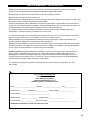
19
Masterbuilt warrants its products to be free from defects in material and workmanship under proper assembly,
normal use and recommended care for 90 days from the date of original retail purchase.
Masterbuilt warranty does not cover paint finish as it may burn off during normal use.
Masterbuilt warranty does not cover rust of the unit.
Masterbuilt requires reasonable proof of purchase for warranty claims and suggests that you keep your receipt. Upon
the expiration of such warranty, all such liability shall terminate.
Within the stated warranty period, Masterbuilt, at its discretion, shall repair or replace defective components free of
charge with owner being responsible for shipping. Should Masterbuilt require return of component(s) in question for
inspection Masterbuilt will be responsible for shipping charges to return requested item.
This warranty excludes property damage sustained due to misuse, abuse, accident, damage arising out of
transportation, or damage incurred by commercial use of this product.
This expressed warranty is the sole warranty given by Masterbuilt and is in lieu of all other warranties, expressed or
implied including implied warranty, merchantability, or fitness for a particular purpose.
Neither Masterbuilt nor the retail establishment selling this product, has authority to make any warranties or to
promise remedies in addition to or inconsistent with those stated above.
Masterbuilt’s maximum liability, in any event, shall not exceed the purchase price of the product paid by the original
consumer/ purchaser. Some states do not allow the exclusion or limitation of incidental or consequential damages.
In such a case, the above limitations or exclusions may not be applicable.
California residents only: Not withstanding this limitation of warranty, the following specific restrictions apply; if
service, repair, or replacement of the product is not commercially practical, the retailer selling the product or
Masterbuilt will refund the purchase price paid for the product, less the amount directly attributable to use by the
original buyer prior to the discovery of the nonconformity. Owner may take the product to the retail establishment
selling this product in order to obtain performance under warranty.
This expressed warranty gives you specific legal rights, and you may also have other rights which vary from
state to state.
Go online www.masterbuilt.com
or complete and return to
Attn: Warranty Registration
Masterbuilt Manufacturing, LLC
1 Masterbuilt Court - Columbus, GA 31907
Name: ___________________________ Address :_________________________ City:________________
State/Province: ________ Postal Code: ________________ Phone Number: (_____) - ____________
E-mail Address:_______________________________________
*Model Number: ____________________ *Serial Number: ____________________
Purchase Date: _____- ______-_______ Place of Purchase: ____________________________________
*Model Number and Serial Number are located on silver label on back of unit.
LIMITED WARRANTY INFORMATION

Masterbuilt Manufacturing, LLC
1 Masterbuilt Ct.
Columbus, GA 31907
Customer Service 1-800-489-1581
Service à la clientèle 1-800-489-1581
Servicio de atención al cliente 1-800-489-1581
www.masterbuilt.com
-
 1
1
-
 2
2
-
 3
3
-
 4
4
-
 5
5
-
 6
6
-
 7
7
-
 8
8
-
 9
9
-
 10
10
-
 11
11
-
 12
12
-
 13
13
-
 14
14
-
 15
15
-
 16
16
-
 17
17
-
 18
18
-
 19
19
-
 20
20


Masterbuilt 20014628 Le manuel du propriétaire
- Catégorie
- Barbecues
- Taper
- Le manuel du propriétaire
dans d''autres langues
- English: Masterbuilt 20014628 Owner's manual
Documents connexes
-
Masterbuilt MB20052318 Le manuel du propriétaire
-
Masterbuilt MPS 340G Manuel utilisateur
-
-
-
-
-
 Masterbuilt Pro MB26050412 Le manuel du propriétaire
-
-
-


