
Not for
Reproduction
Operator’s Manual
CE 50 Hz Night-Lite Pro II
®
Bedienungsanleitung
CE 50 Hz Night-Lite Pro II
®
Manual del operario
CE 50 Hz Night-Lite Pro II
®
Manuel d'utilisation
CE 50 Hz Night-Lite Pro II
®
Copyright © 2015 Briggs & Stratton Corporation
Milwaukee, WI, USA. All rights reserved.
Part No.: 104887
Revision: -
en
de
es
fr

Not for
Reproduction
2
www.allmand.com
1 2
4
A
B
C
D
5
A
D
E
C
B
3
B
C
A
D
G
H
B
B
L
A
I
C
J K
D E F

Not for
Reproduction
3
en
7
B
A
8
G
A
C
E
D
B
F
10
A
A
11
A
12
A
6
A
C
D
B
A
9

Not for
Reproduction
4
www.allmand.com
19
A
15
A
B
16
A
B
14
C
B
A
B
A
17
B
A
18
13
A

Not for
Reproduction
5
en
20
A
21
A
22
A
A
23
C
B
A
24

Not for
Reproduction
6
www.allmand.com
28
C
A
B
G
F F
E
29
A
B
25
A
B
26
A
27

Not for
Reproduction
7
en
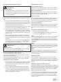
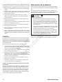
Record Important Information
Recording the equipment information will help when placing
an order for replacement parts and/or decals.
Company Equipment No:____________________________
Unit model No:____________________________________
Unit Vin:_________________________________________
Engine Model No: ____________Serial No:_____________
Generator Model No:__________Serial No:_____________
Accessories:_____________________________________
_______________________________________________
_______________________________________________
Manual Contents:
Introduction ........................................................................7
Safety ...................................................................................7
Trailering, Transporting and Lifting ............................... 11
General Service Information .......................................... 14
Operation ......................................................................... 16
Maintenance .................................................................... 19
Troubleshooting .............................................................. 22
Warranty ........................................................................... 24
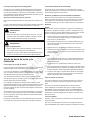
Introduction
About This Manual
TAKE TIME TO READ THIS MANUAL THOROUGHLY
This instruction manual provides necessary instructions for
the NIGHT-LITE PRO II light tower.
The information found in this manual is in effect at the time
of printing. Allmand Bros Inc. may change contents without
notice and without incurring obligation.
Any reference in this manual to left or right shall be deter-
mined by looking at the trailer from the rear.
If you are uncertain about any of the information in the manu-
al, contact Allmand service department at +800.562.1373, or
contact us through the Allmand website, www.allmand.com.
Save these original instructions for future reference.
Products Covered by This Manual
The following products are covered by this manual:
CE 50HZ NIGHT-LITE PRO II
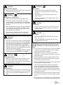
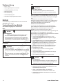
Safety
Safety Definitions
Safety statements are one of the primary ways to call your
attention to potential hazards. Follow the precautions listed
throughout the manual before operation, during operation
and during periodic maintenance procedures for your safety,
the safety of others and to protect the performance of equip-
ment. Keep the decals from becoming dirty or torn and
replace them if they are lost or damaged. Also, if a part needs
to be replaced that has a decal attached to it, make sure to
order the new part and decal at the same time.
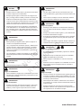
This safety alert symbol appears with most safety
statements. It means attention, become alert, your
safety is involved! Read and abide by the message
that follows the safety alert symbol.
DANGER
Indicates a hazardous situation which, if not avoided, will
result in death or serious injury.
WARNING
Indicates a hazardous situation which, if not avoided, could
result in death or serious injury.
CAUTION
Indicates a hazardous situation which, if not avoided, could
result in minor or serious injury.
NOTICE
Indicates a situation which can cause damage to the equip-
ment, personal property and/or the environment, or cause the
equipment to operate improperly.
NOTE:
Provides key information to make procedures easier or clear-
er.
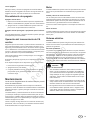
Safety Precautions
The following section contains general safety precautions
and guidelines that must be followed to reduce risk to per-
sonal safety. Special safety precautions are listed in specific
procedures. Read and understand all of the safety precau-
tions before operating or performing repairs or maintenance.

Not for
Reproduction
8
www.allmand.com
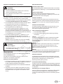
DANGER
Electrocution Hazard
• Always check overhead wires and obstructions before
raising or lowering the light tower.
• Always follow the rules or instructions for your worksite
and state, province or national electric code for main-
taining a safe distance from overhead wires.
• High voltage is present when engine is running. Never
attempt to service electrical components while engine
is running.
• Do not operate the light tower if the insulation on the
electrical cord or other electrical wiring is cut or worn
or if bare wires are exposed. Repair or replace dam-
aged wiring before starting the engine.
WARNING
Unsafe Operation Hazard
• Never permit anyone to install or operate the equip-
ment without proper training.
• Read and understand this Operator’s Manual and the
Engine Operator’s Manual before operating or servic-
ing the light tower to ensure that safe operating prac-
tices and maintenance procedures are followed.
• Safety signs and decals are additional reminders for
safe operating and maintenance techniques.
WARNING
Fall Hazard
• Never carry riders on the equipment.
WARNING
Modification Hazard
• Never modify the equipment without written consent of
the manufacturer. Any modification can effect the safe
operation of the equipment.
WARNING
Exposure Hazard
• Always wear personal protective equipment, including
appropriate clothing, gloves, work shoes, and eye and
hearing protection, as required by the task at hand.
WARNING
Rollover Hazard
• Do not raise, lower or use light tower unless all outrig-
gers and jacks are positioned on firm ground.
• Never move or reposition the light tower while the light
tower is extended in the vertical position.
WARNING
Explosion Hazard
• Keep the area around the battery well ventilated and
keep sparks, open flame and any other form of ignition
out of the area.
• Always disconnect the negative (-) battery cable
before servicing equipment.
• Only use the starting procedure as described in the
Engine Operator’s Manual to start the engine.
• Never charge a frozen battery. Always slowly warm the
battery to room temperature before charging.
WARNING
Fire And Explosion Hazard
• Diesel fuel is flammable and explosive under certain
conditions.
• Never use a shop rag to catch fuel.
• Wipe up all spills immediately.
• Never refuel with the engine running.
• Store any containers containing fuel in a well venti-
lated area, away from any combustibles or sources of
ignition.
WARNING
Exhaust Hazard
• All internal combustion engines create carbon monox-
ide gas during operation and special precautions are
required to avoid carbon monoxide poisoning.
• Never block windows, vents or other means of ventila-
tion if the equipment is operating in an enclosed area.
• Always ensure that all connections are tightened to
specifications after repair is made to the exhaust sys-
tem.

Not for
Reproduction
9
en
WARNING
Alcohol And Drug Hazard
• Never operate the light tower while under the influence
of alcohol or drugs, or when ill.
WARNING
Entanglement / Sever Hazard
• Always stop the engine before beginning service.
• If the engine must be service while it is operating,
remove all jewelry, tie back long hair and keep hands,
other body parts and clothing away from moving/rotat-
ing parts.
• Verify that all guards and covers are attached properly
to the equipment before starting the engine. Do not
start the engine if any guards or covers are not prop-
erly installed on the equipment.
• Attach a “Do Not Operate” tag near the key switch
while performing maintenance on the equipment.
WARNING
Piercing Hazard
• Avoid skin contact with high pressure hydraulic fluid or
diesel fuel spray caused by a hydraulic or fuel system
leak such as a broken hydraulic hose or fuel injection
line. High pressure hydraulic fluid or fuel can pen-
etrate your skin and result in serious injury. If you are
exposed to high pressure hydraulic fluid or fuel spray,
obtain prompt medical treatment.
• Never check for a hydraulic fluid or fuel leak with your
hands. Always use a piece of wood or cardboard.
WARNING
Flying Object Hazard
• Always wear eye protection when cleaning the equip-
ment with compressed air or high pressure water.
Dust, flying debris, compressed air, pressurized water
or steam may injure your eyes.
WARNING
Coolant Hazard
• Wear eye protection and rubber gloves when handling
engine coolant. If contact with the eyes or skin should
occur, flush eyes and wash immediately with clean
water.
WARNING
Burn Hazard
• Light fixtures and some of the engine surfaces
become very hot during operation and shortly after
shutdown.
• Keep hands and other body parts away from hot
engine surfaces.
• Handle hot components, such as light fixtures, with
heat resistant gloves.
CAUTION
Tool Hazard
• Always use tools appropriate for the task at hand and
use the correct size tool for loosening or tightening
equipment parts.
CAUTION
Slip Hazard
• Immediately clean up any spilled liquid on the shop
floor.
• Clean up accumulated dirt and debris on the shop
floor at the end of each shift.
NOTICE
The statements that follow have NOTICE level issues.
Damage to equipment or property can result if not fol-
lowed.
• Any part which is found defective as a result of inspection
or any part whose measured value does not satisfy the
standard or limit MUST be replaced.
• Always tighten components to the specified torque.
Loose parts can cause equipment damage or cause it to
operate improperly.
• Follow the guidelines of governmental agencies for the
proper disposal of hazardous materials such as engine
oil, diesel fuel and engine coolant.
• Only use replacement parts specified. Other replacement
parts may effect warranty coverage.
• Clean all accumulated dirt and debris away from the
body of the equipment and its components before you
inspect the equipment or perform preventative mainte-
nance procedures or repairs. Operating equipment with
accumulated dirt and debris will cause premature wear of
equipment components.
• Never dispose of hazardous materials by dumping them
into a sewer, on the ground, or into groundwater or water-
ways.
• Retrieve any tools or parts that may have dropped inside
of the equipment to avoid improper equipment operation.

Not for
Reproduction
10
www.allmand.com
• If any alert indicator illuminates during equipment opera-
tion, stop the engine immediately. Determine the cause
and repair the problem before continuing to operate the
equipment.
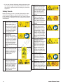
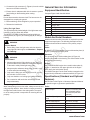
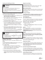
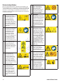
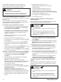
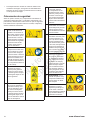
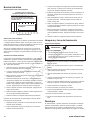
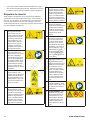
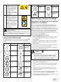
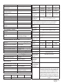
Safety Decals
Before operating your unit, read and understand the safety
decals (compare Figure 1 with the table below). The cau-
tions, warnings, and instructions are for your safety. To avoid
personal injury or damage to the unit, understand and follow
all the decals.
A DANGER - Contacting
Power Lines. Contacting
electric power lines
when elevating the light
tower will result in death
or serious injury. Always
maintain a safe distance
from power lines when
elevating the tower.
B DANGER - Contacting
High Voltage
Components. Contact
with high voltage compo-
nents will result in death
or serious injury. Always
read the instructions in
the Operator’s Manual
before servicing high
voltage electrical compo-
nents.
C WARNING - Rotating
Parts. Contact with rotat-
ing parts could result in
death or serious injury.
Always keep clear of
rotating parts.
D WARNING - Lowering
Light Tower. Standing
under the light tower
when it is being lowered
could result in death or
serious injury. Always
stay clear of the light
tower when the tower is
being lowered.
E WARNING - Hot Light
Fixtures. Handling light
fixtures when they are
hot could result in death
or serious injury. Always
keep clear of light fix-
tures when illuminated
or hot.
F WARNING - Bright
Lights. Looking at an
illuminated light fixture
could result in serious
injury. Never look directly
at an illuminated light
fixture.
G WARNING - Automatic
Engine Start (models
equipped with LSC 2.0
only). Engine may start
unexpectedly. To avoid
serious injury or death,
always read instructions
in LSC 2.0 Operator’s
Manual before servicing
engine.
H WARNING - Use
Outriggers. Elevating
light tower without
deploying the outriggers
could cause machine
to tip over and result in
death or serious injury.
Always deploy the out-
riggers on a firm level
surface and make sure
machine is level before
raising the tower.
I WARNING - Read
Operator’s Manual.
Read and understand
the Operator’s Manual
before operating this
machine.
J WARNING - Explosive
Gases. Explosive gases
could result in death or
serious injury. Keep open
flame and lighted materi-
als away from battery.

Not for
Reproduction
11
en
WARNING
If any safety or instructional decals become worn or dam-
aged, and cannot be read, order replacement decals from
your dealer.
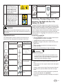
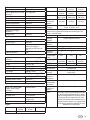
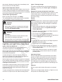
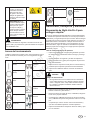
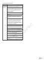
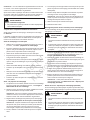
Operation Icons
The following table contains operation icons that may be
found on the unit, along with the meaning of each icon.
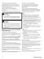
Trailering, Transporting And Lifting
Preparing The Night-Lite Pro II For
Delivery Or Rental
The NIGHT-LITE PRO II light tower requires service as well
as proper operation in order to provide the performance and
safety it has been designed for. Never deliver or put machine
into service with known defects or missing instructions or
decals. Always instruct the customer in proper operation and
safety procedures as described in this Operator’s Manual.
Always provide the manual with the equipment for proper and
safe operation.
Pre-Operation Check List
• Visually inspect the equipment to ensure that all instruc-
tions and decals are in place and legible
• Check the hitch assembly and breakaway wire.
• Check the outriggers and jacks to make sure they oper-
ate properly.
• Inspect the light assemblies for damage and test for
proper operation.
• Inspect the electrical wiring for signs of damage.
DANGER
Electrocution Hazard
• Do not operate the light tower if the insulation on the
electrical cords or other electrical wiring is cut or worn,
or if bare wires are exposed. Repair or replace dam-
aged wiring before starting the engine.
• Inspect tires to insure good condition and proper infla-
tion.
• Check engine oil, fuel, engine coolant levels and hydrau-
lic fluid level.
• Check to make sure the Light Tower Operator’s Manual
and Generator Operator’s Manual are with the equip-
ment.
• Check to make sure that the hand brake is operational
and properly adjusted. See Operation.
• Inspect the machine physically for damage and repair if
necessary.
K WARNING - Corrosive
Material. Exposure to
corrosive material could
result in death or seri-
ous injury. Always wear
protective gloves when
handling battery.
L WARNING - Roll Over
Hazard. Performing high
speed sharp turns could
cause trailer to roll over
resulting in death or seri-
ous injury. Always slow
to a safe speed when
performing sharp turns.
104883
Icon Meaning Icon Meaning
On (Power) Trailer Interior
Light
Off (Power) Earth Ground
Engine Stop Circuit Breaker
Engine Run Disconnecting
Circuit Breaker
Engine Start Raise Light Tower
Engine Preheat Lower Light
Tower
Icon Meaning Icon Meaning
Hourmeter Engine Oil Drain
Worklight Fluid
Containment
Drain

Not for
Reproduction
12
www.allmand.com
NOTE: See appropriate section of the Engine Operator’s
Manual and Generator Operator’s Manual for additional pre-
operation checks.
After completing the pre-operation check list, operate the
tower through a complete operation cycle, following the oper-
ating instructions contained in this manual.
WARNING
Unsafe Operation Hazard
• Never permit anyone to install or operate the equip-
ment without proper training.
Always Read And Understand The Instructions First.
Before trailering, transporting or lifting, read Safety.
The complete engine and generator set is housed in a lock-
able enclosure with the frame fabricated from heavy gauge
steel mounted on a two-wheel, torsion bar axle.
Before Trailering Or Transporting
• Lower the light tower and shut down the tower lights and
the engine; See Shutdown – Prepare For Trailering.
• Visually inspect the trailer and equipment for damage.
Repair or replace any components as needed before
trailering.
• Check the trailer lights for proper operation.
• Inspect the tires to insure good condition and proper
inflation.
• Inspect trailer axle and undercarriage for damage or
loose parts.
• Check the hitch assembly and breakaway wire.
• Ensure the outriggers and jacks are properly stowed.
• Clean any spills from inside the trailer fluid containment
area that may have occurred during operation.
• Ensure all compartment doors are closed and securely
locked.
Shutdown – Prepare for Trailering
1. With the tower lights off, lower the light tower to the full
DOWN position; See Raising And Lowering The Light
Tower.
2. Turn the engine off. Refer to your Engine Operator’s
Manual for stopping procedure.
NOTE: See appropriate section of the Engine Operator
Manual and Generator Operator’s Manual for additional
post – operation and shutdown procedures.
3. Adjust the light bar and light fixtures for trailering; see
Tower Light – Stowage For Trailering.
NOTE: Visually inspect the light mounting brackets and
hardware for loose fasteners or damaged brackets.
Repair any problems before trailering.
4. Close, secure and lock all compartment doors.
5. Raise each rear stabilizer jack and rotate into trailering
position (horizontal with outrigger bar).
6. Retract each outrigger bar and secure in the stowed
position with latch pin.
NOTE: Be sure each outrigger jack is securely latched in
transporting position by installing the outrigger lock pins
before transporting.
7. Connect the trailer to the tow vehicle.
8. Release the hand brake.
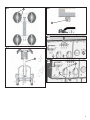
Vertical Tower Lights – Stowage for Trailering
The light bar and fixtures must be stowed before trailering or
transporting.
WARNING
Burn Hazard
• The light fixtures become extremely hot during use.
• Always use caution and heat–resistant glove when
handling the lights or allow the lights to sufficiency cool
down before handling.
1. Ensure lights are off and tower is lowered to the full
DOWN position; see Raising And Lowering The Light
Tower.
2. Release the light bar park pin by pulling the ring and turn-
ing it 90 degrees so that the pin remains in the retracted
position.
3. Rotate the light bar into the trailering / transport park
position (in line with the trailer) and engage the park pin
by twisting the park pin ring until the plunger is released
and the pin engages and locks into the hole in the light
bar.
4. Reposition the light fixtures for trailer / transport by pulling
them down into the lowest position and face the fixtures
toward the center of the trailer. See Figure 2.
NOTE: If lights are to be removed for trailering / trans-
porting, see Tower Lights – Removal For Trailering
(Optional).
Tower Lights – Removal For Trailering (Optional)
Your light tower may be equipped with lights that can be
removed for trailering / transport or for theft prevention.
WARNING
Burn Hazard
• The light fixtures become extremely hot during use.
• Always use caution and heat–resistant glove when
handling the lights or allow the lights to sufficiency cool
down before handling.

Not for
Reproduction
13
en
1. Ensure lights are off and tower is lowered to the full
DOWN position; see Raising And Lowering The Light
Tower.
2. Disconnect the electrical cord for each light fixture at the
light bar.
3. While supporting the light fixture, remove the nut and
washer assembly fastening the main fixture bracket and
remove each light fixture and bracket.
4. Store each light fixture to avoid any damage during trans-
port.
Trailering / Towing
Before trailering / towing the light tower trailer, read Safety
and Before Trailering Or Transporting.
NOTICE:
Maximum highway speed is 90 km/h (56 mph) and maximum
off highway speed is 15km/h (9.5 mph). Do not exceed these
limits or damage to light tower may occur.
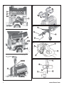
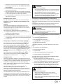
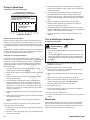
Trailer Component Identification (Figure 3)
A. Tongue Jack – Used to raise, lower and level trailer
tongue.
B. Pintle Ring Hitch Coupler - 40mm (1-9/16 inch)
C. Breakaway Wire – Safety connection to tow vehicle that
activates brakes if coupler disconnects.
D. Hand Brake
Towing Vehicle and Hitch Considerations
The towing vehicle must be able to safely pull the full trailer
load. Never pull a trailer load that exceeds the vehicle’s
towing capacity; you risk losing control of the trailer and/or
vehicle. Before trailering, always check your vehicle owner’s
manual for maximum towing/trailering load specifications and
maximum gross vehicle weight specifications that include the
fully loaded trailer.
The vehicle must have a towing hitch that is capable of safely
handling the trailering load and tongue weight of the trailer.
Trailer Brakes
The CE NIGHT-LITE PRO II is equipped with service brakes
and a hand brake. The service brakes operate when the light
tower trailer is connected to the tow vehicle. When the towing
vehicle is braking or traveling downhill, the overrun device
acts through the linking components to apply the wheel
brakes.
When the towing vehicle is reversing, the overrun device acts
through the linking components to begin applying the wheel
brakes. However, the backwards rotation of the drum acts on
internal components to cancel out the brake effect, allowing
the trailer to move backwards.
The hand brake operates by pulling the lever until upright
to set the wheel brakes. Note that with the hand brake fully
applied, the trailer is able to move backwards up to 25cm (10
inches) until the gas cylinder in the linkage takes effect.
WARNING
Control Hazard
• A vehicle hitch that is underrated or improperly
installed can lead to loss of control of the trailer and/or
vehicle.
• Never use a hitch size or rating that does not match
the trailer coupler specifications.
Connecting the Trailer Hitch Coupler and Lights
The trailer is equipped with a 40mm (1-9/16 inch) lunette ring.
A trailer coupler for a 50mm (1-31/32 inch) ball hitch is avail-
able.
To change the coupler, remove the two bolts and replace the
existing coupler with the desired coupler.
WARNING
Control Hazard
• Ensure the coupler bolts are tightened before traile-
ring.
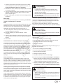
Typical Lunette Ring Pintle Type Hitch and Coupler (Figure 4)
A. Latch and Release Lever
B. Trailer Coupler Lunette Ring
C. Latch Lever Safety Pin
D. Vehicle Hitch
Typical Ball Type Hitch and Coupler (Figure 5; if equipped)
A. Latch and Release Lever
B. Trailer Coupler Socket
C. Coupler Clamp
D. Vehicle Hitch and Ball
E. Latch Lever Safety Pin
Before trailering, read Before Trailering Or Transporting.
1. Connect the tow vehicle hitch to the trailer coupler. Make
sure the coupler is securely attached to the tow vehicle’s
hitch.
2. Connect the breakaway wire (A, Figure 6) to the vehicle’s
hitch frame (B); this will activate the unit’s service brakes
in the event the unit accidentally disconnects from the
towing vehicle.
WARNING
Control Hazard
• Attach the breakaway wire properly and securely
between the towing vehicle and trailer before trailering.
• Never allow the breakaway wire to drag the ground
when trailering.

Not for
Reproduction
14
www.allmand.com
3. Connect the light connector (C, Figure 6) from the vehicle
harness to the trailer socket (D).
4. Ensure there is adequate slack in the harness to prevent
from binding or disconnecting when turning.
NOTICE:
Do not allow excessive harness slack. The harness can be
damaged from scraping the ground.
5. Before trailering, check all lights for proper operation.
6. Release the hand brake.
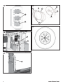
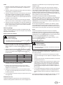
Lifting The Light Tower
The approximate fully loaded weight of the light tower trailer
is 820 kg (1807 lbs) when fully fueled.
The NIGHT-LITE PRO II light tower is equipped with top
forklift pockets (A, Figure 7) and a lifting eye (B) for lifting or
hoisting.
WARNING
Rollover Hazard
• Before lifting, lower the light tower and shut down the
tower lights and the engine; see Shutdown – Prepare
for Trailering.
WARNING
Crush Hazard
• Always make sure the lifting device you are using is in
good condition and is rated for the maximum capacity
of the task to safely lift the light tower trailer.
• Always acquire assistance when using a forklift, crane
or hoist and when unloading.
• Only use the lifting eye on the lifting bar to lift or hoist
the unit with a hoist or crane.
• Only use shackles or a locking-type hook when lifting.
• Do not stand or walk under the unit when lifted and
keep others away.
Transporting On A Trailer
When transporting on a truck or trailer, always secure the unit
using properly rated tie - down chains or straps connecting
the light tower trailer frame to the towing trailer. The opera-
tor of the towing vehicle is responsible for securing the load
properly.
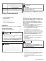
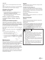
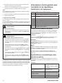
General Service Information
Equipment Identification
Compare Figure 8 with the table below.
Ref Description
A 40mm (1-9/16 inch) Pintle Hitch (standard)
A 50mm (1-31/32 inch) Ball (not shown - optional)
B Parking Brake
C Tongue Jack
D Outrigger Stabilizer (one each side)
E Outrigger (shown retracted)
F Rear Stabilizer
G Park Pin
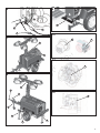
Model And Serial Numbers
Model and serial number information is required for product
support and repair parts. The following descriptions show
model and serial number locations of the primary compo-
nents.
Trailer
All NIGHT-LITE PRO II trailers have a serial number plate (A,
Figure 9) attached to the front panel.
Generator
The generator has a serial number plate (A, Figure 10)
attached to the side of the housing. The serial number is also
stamped into the housing.
Engine
The CATERPILLAR
®
engine has a serial number plate (A,
Figure 11) attached on the upper right side of the engine
block above the fuel injection pump.
The KUBOTA engine has the serial number stamped on the
engine block just below the exhaust manifold (A, Figure 12).
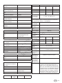
Specifications (Standard and Optional
Features)
NOTE: Refer to the Engine or Generator Operator’s Manual
for specific engine or generator specifications.
Trailer
Hitch Coupler 40mm (1-9/16 inch) pintle
hitch (standard); 50mm
(1-31/32 inch) ball hitch
(optional)
Max Road Speed (paved
road)
90 km/h (56 mph)
Max Off-Road Speed 16,1 km/h (10 mph)
Number of Axles 1
Axle Rating 907 kg (2000 lb)
Tire Size 155R13C-8PR 90/88Q
Rim Size 4.5J x 13

Not for
Reproduction
15
en
Cold Tire Inflation Pressure 310 kPa (45 psi)
Door Locks Standard
Trailer Lights: Stop, Turn and
Running
ECC approved
Trailer Light Connector 13-Pin plug
Lifting Eye Standard
Tie-Down Rings Standard
Rear Forklift Pockets Standard
Top Forklift Pockets Standard
Number of Stabilizers 4
Number of Outrigger
Stabilizers
2
Tongue Jack Standard
Light Tower - Vertical
Sections 6
Vertical Tower Standard
Max Continuous Wind Load 85 km/h (53 mph) - with
jacks and outriggers
deployed on firm level sur-
face
Light Bar Rotation 360°
Overall Dimensions - Vertical Tower
Light Tower Height -
Lowered
2,54m (8’ 4”)
Light Tower Height - Raised 7,9m (25’)
Length 2,85m (9’ 4”)
Width (outriggers retracted) 1,3m (4’ 3”)
Width (outriggers extended) 2,54m (8’ 4”)
Dry Weight 790 kg (1740 lb)
50Hz Generators
6 kW Standard
220VAC Shucko Outlet Standard
230VAC Optional
Tower Lights
SHO - HD 1000W Metal
Halide (lumen rating:
110,000)
Standard 50Hz
Warm-Up Time 2-4 minutes
Re-Start Time 10-15 minutes
Light Fixtures Standard (sealed for all
weather use)
Light Fixture Weight 6,75 kg (15 lb)
Engine
Model Kubota
D1005
Kubota
D1105
CAT C1.1
Type Water Cooled 4-Cylinder Diesel
Bore 76mm
(2.99 in)
78mm
(3.07 in)
77mm
(3.03 in)
Stroke 73,7mm
(2.90 in)
78mm
(3.09 in)
81mm
(3.19 in)
Displacement 1001cc
(61.1 cu in)
1123cc
(68.5 cu in)
1130cc
(69 cu in)
Power
@1500rpm
(50Hz)
8,2kW
(11.0hp)
9,5kW
(12.7hp)
8,6kW
(11.5hp)
Power Outlet
Derating
3% per 1000ft above 360ft
1% per 10° above 70° F
NOTE: Horsepower ratings are established in accordance
with Society of Automotive Engineers Small Engine Test
Code - J1349 GROSS
Fuel System Indirect Injected Diesel
Starting
System
12VDC Negative Ground
Electrical
System
12VDC Negative Ground
Battery Type Group 24
Battery Rating 550 CCA
Number of
Batteries
1
Compression
Ratio
22.1 22.1 23.1
Weight 109kg
(204.3 lb)
109kg
(204.3 lb)
87kg
(191 lbs)
Oil Capacity 5,1L (5.4 qt) 5,1L (5.4 qt) 3,7L (3.9 qt)
Lubrication Forced Lubrication By Pump
Oil Filtratrion Cartridge Type
Cooling
System
Pressurized radiator forced circulation with
water pump
Low Oil
Pressure
Shutdown
Standard all engines
High Engine
Temperature
Shutdown
Standard all engines
Glow Plug
Cold Start
Assist
Standard all engines
Fuel For those countries governed by the rules
of the European Community (EC), diesel
fuels that meet EN590 for Ultra Low Sulfer
Diesel (ULSD) are required to be used.
Diesel fuels meeting this standard have a
maximum sulfer content of 10 mg/kg. Refer
to the Engine Operator’s Manual for more
detailed fuel requirements.

Not for
Reproduction
16
www.allmand.com
Engine Oil Use a high quality engine oil of API
(American Petroleum Institute) service
class CG-4/CH-4/CI-4. Refer to the Engine
Operator’s Manual for more detailed
engine oil requirements.
Fuel Tank 114 L (30 gal)
Cooling Tank 5.2 L (5.5 qt)
Overflow
Reservoir
1.04 L (1.09 qt)
Optional Accessory Equipment
• Saf - T - Visor
• LSC2.0 Light Sequence Commander
• Heavy Duty Battery (775 CCA)
• Battery Heating Pad
• Engine Block Heater
• Sound Attenuation package
• Quick - Disconnect Lamp Fixtures
Operation
Before performing any operation procedures, read Safety.
Pre-Operation Setup
Work Site Safety Considerations
Height
DANGER
Electrocution Hazard
• Always check overhead wires and obstructions before
raising or lowering the light tower.
• Always follow the rules or instructions for your worksite
and state, province or national electric code for main-
taining a safe distance from overhead wires.
Ground Surface
WARNING
Rollover Hazard
• Rollover Hazard. Do not set up on an incline of more
than 2.8° (5% grade) front-to-back and side-to-side.
• Do not position or set up on unlevel or unstable
ground. Only set up on smooth, flat and solid ground
surfaces.
Wind
WARNING
Rollover Hazard
• Do not operate with the light tower extended in winds
exceeding 85 km/h (53 mph).
When the light tower is in the operating position it is located
in the middle of a three-point outrigger system for optimum
balance and stability. This system was engineered to allow
the light tower to remain operational in sustained winds of 85
km/h (53 mph) with the light tower extended to full height and
the jacks and outriggers in position on a firm level surface.
Pre-Operation Check List
Always perform the following checks before traveling to the
work site and before operation. Repair or replace any compo-
nents as required before operation.
NOTE: See appropiate section of the Engine Operator’s
Manual and Generator’Operator’s Manual for additional pre-
operation checks.
After completing the pre-operation check list, operate the
light tower through a complete operation cycle.
• Visually inspect the equipment to ensure that all instruc-
tions and decals are in place and legible.
• Check the hitch assembly and breakaway wire.
• Check to make sure the hand brake is operational: Pull
up on the hand brake lever (B, Figure 8) to set the hand
brake and lock the trailer wheels. Press the release but-
ton on the end of the hand brake lever and lower the
brake lever to release the hand brake.
• Check the outriggers and jacks to make sure they oper-
ate properly.
• Inspect the light assemblies for damage and test for
proper operation.
• Inspect electrical wiring for signs of damage.
DANGER
Electrocution Hazard
• Do not operate the light tower if the insulation on the
electrical cords or other electrical wiring is cut or worn,
or if bare wires are exposed.
• Inspect the tires to ensure good condition and proper
inflation.
• Check engine oil, fuel, engine coolant levels and hydrau-
lic fluid levels.
• Check to make sure the Light Tower Operator’s Manual,
Engine Operator’ Manual and Generator Operator’s
Manual are with the equipment.
• Physically inspect the machine for damage and repair if
necessary.

Not for
Reproduction
17
en
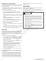
Leveling and Stabilizing the Trailer
WARNING
Rollover Hazard
• Do not set up on unlevel ground. Only set up on
smooth, flat and solid ground surfaces.
• Always level the light tower trailer before raising the
light tower.
The NIGHT-LITE PRO II must be leveled to 2.8° (5% grade)
or less, front-to-back and side-to-side.
1. Position the NIGHT-LITE PRO II on an adequate site; see
Work Site Safety Considerations.
2. Set the hand brake, and block each wheel on each side
with a suitable wheel chock (A, Figure 13).
3. Extend the outrigger stabilizers, and lock in place with
the outrigger lock pin (A, Figure 14).
4. Rotate each outrigger stabilizer jack (Figure 14), as well
as the rear stabilizer jack (Figure 15) and tongue jack
(Figure 16), perpendicular with the ground, and lock
each in place with the jack pin (B, Figure 14; A, Figures
15 and 16).
5. Adjust each outrigger stabilizer jack (C, Figure 14), the
rear stabilizer jack (B, Figure 15) and the tongue jack (B,
Figure 16) to achieve proper leveling.
NOTE: Turning the handles clockwise will raise the jacks,
and counterclockwise will lower the jacks.
WARNING
Rollover Hazard
• All stabilizer jacks must be supported by a flat, level
solid ground surface.
Engine Operation
Before starting the engine or operating the light tower, read
Safety.
The Allmand NIGHT-LITE PRO II Series light towers are pow-
ered by a diesel engine and generator unit.
Pre - Start Checks
1. Check the engine oil and add oil if required. Fill the
engine with the proper grade of lubricating oil; refer to the
Engine Operator’s Manual for oil specifications.
2. Check and add diesel fuel as required.
3. Ensure that the air cleaner is firmly attached and air
cleaner seals and hose clamps are properly sealed. Air
cleaner element should be checked and replaced if nec-
essary.
Engine Control Panel
Standard Control Panel
The standard engine control panel consists of the engine
start/stop key (A, Figure 17) and hour meter (B).
LSC 2.0 Control Panel
The LSC 2.0 engine control panel consists of the main panel
on/off switch (A, Figure 18), and LSC 2.0 control panel with
LCD display (B).
Starting the Engine
The Starting procedure is different depending on the engine
model used. Refer to your Engine Operator’s Manual for
the starting procedure. For LSC 2.0, refer to the LSC 2.0
Operator’s Manual.
Cold - Weather Starting
The cold - weather starting procedure is different depending
on the engine model used. Refer to your Engine Operator’s
Manual for the cold - starting procedure.
If Engine has Run Out of Fuel
1. Refill the fuel tank.
2. Refer to your Engine Operator’s Manual for the starting
procedure.
Notice:
Do not operate starter for more than 10 seconds without
allowing 30 seconds to pass between starting attempts.
Possible starter damage could result from excessive heat
caused by cranking too long.
Notice:
If the engine develops sufficient speed to disengage the
starter but does not keep running (a false start), the engine
rotation must be allowed to come to a complete stop before
attempting to restart the engine.
Notice:
If starter is engaged while the flywheel is rotating, the starter
pinion and flywheel ring gear may clash, resulting in damage
to the starter or flywheel ring gear.
Stopping the Engine
The engine stopping procedure may differ depending on the
engine model. Refer to your Engine Operator’s Manual for
engine stopping procedures. For LSC 2.0, refer to the LSC
2.0 Operator’s Manual.
Automatic Engine Shutdown System
The engine is equipped with an automatic engine shutdown
system to prevent excessive engine damage in the event of a
low oil or overheat condition. For additional information, refer
to your Engine Operator’s Manual.
Low Oil Pressure Shutoff
Should a low oil pressure condition occur, the oil pressure
sending unit breaks the circuit between the battery and the

Not for
Reproduction
18
www.allmand.com
fuel solenoid, allowing the spring load to immediately move
the fuel control to the shutoff position.
High Coolant Temperature Shutoff
Should a high coolant temperature condition occur, the tem-
perature sending unit breaks the circuit between the battery
and the fuel solenoid, allowing the spring load to immediately
move the fuel control to the shutoff position.
Vertical Tower Light Operation
Before operating the tower lights, read Safety.
The vertical light tower is raised and lowered by a hydraulic
pump actuating a 6-section telescoping mast.
WARNING
Rollover Hazard
• Before raising, lowering or operating the tower lights,
the trailer must be set up, properly leveled and stabi-
lized: see Pre-Operation Setup.
WARNING
Crush Hazard
• Allow adequate clearance around and above trailer
when raising or lowering the light tower.
• Ensure that there are no obstructions or persons near
the light tower when raising or lowering the light tower.
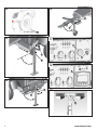
Light Bar and Light Fixture Adjustment
Lights - Work Site Adjustment
The light bar and light fixtures must be adjusted to the
desired work angle before raising the light tower.
With the light tower fully lowered and the lights off, the light
bar assembly and light fixtures can be manually rotated into
the desired working position.
To adjust the light bar, release the light bar park pin (A,
Figure 19) by pulling the ring and turning it 90 degrees so
that the pin remains in the retracted position.
With the light bar park pin released, the light bar is designed
to be manually rotated with enough resistance so that the bar
will stay in the desired position once the operator has direct-
ed the lights on the work zone.
If the light bar rotates too easily or does not stay in position,
remove the cap plug from the center of the light bar cover
and tighen the nut to achieve the desired resistance and
replace the cap plug.
To adjust each light fixture, manually swivel each light fixture
at its base (A, Figure 20) into the desired working position.
Lights - Trailering Storage
The light bar and light fixtures must be stowed properly for
trailering or transporting. See Tower Lights - Stowage for
Trailering.
Raising and Lowering the Hydraulic Light Tower
NOTE: The hydraulic actuated light tower (A, Figure 21) uses
12VDC battery power to operate. The light tower may be
raised and lowered as needed with the ignition on but without
the engine running.
Raising
NOTICE:
Before raising light tower, visually inspect equipment for dam-
age or wear and repair or replace components as required.
Never operate the light tower with damaged or malfunction-
ing components.
1. Before raising the light tower, adjust the tower lights to
the desired work position; see Light Bar and Light
Fixture Adjustment.
2. If required, start engine. Refer to your Engine Operator’s
Manual for starting procedure.
3. Turn the lights off; see Light Control Panel.
4. Press the light tower hydraulic lift switch (A, Figure 22) up
to raise the light tower to the desired height.
Lowering
1. If required, start engine. Refer to your Engine Operator’s
Manual for starting procedure.
2. Turn the lights off; see Light Control Panel.
3. Press the tower light hydraulic lift switch (A, Figure 22)
down to lower the light tower to the desired height or to
the full DOWN position.
4. When tower reaches the bottom, run switch for 3 addi-
tional seconds to ensure that the tower is at its lowest
possible position.
Light Control Panel
The four tower light fixtures are protected by four breaker
switches (A, Figure 23) located on the light control panel.
The lights are automatically controlled by the sequenced
lighting system (SLS). Simply leave the breaker switches
in the ON position for automatic light control. However, the
breaker switches may be turned OFF for individual light con-
trol.
Lights On
Start the engine and the lights will sequence on automati-
cally.
Turn one or more light breaker switches (A, Figure 23) to the
OFF position for individual light control.

Not for
Reproduction
19
en
Lights Off
Turn the engine off, and the lights will shut down automati-
cally.
NOTE: The lights will turn off a fraction of a second ahead of
engine shutdown; this prevents capacitor damage.
Shutdown Procedure
Shutdown - Short period
1. Lower the light tower to the full DOWN position; see
Raising and Lowering the Light Tower.
2. Turn the engine off. Refer to your Engine Operator’s
Manual for stopping procedure.
Shutdown - Long-Term or Prepare for Trailering
See Long-Term Storage or Shutdown - Prepare for
Trailering.
Auxiliary AC Outlet Operation
Depending on model options, the 220VAC 1-phase control
panel is equipped with two 220VAC outlets (C, Figure 24) for
powering accessories from the generator. Power is supplied
to the outlets only when the engine / generator is running and
the main circuit breaker (A) is in the ON position.
Each 220VAC outlet is protected by a 15A circuit breaker (B,
Figure 24).
The main circuit breaker (A, Figure 24) is a 32A ELCB circuit
breaker.
If any of the outlet circuit breakers trip:
1. Disconnect the load from the outlet.
2. Turn off the tower lights (if used).
3. Correct the excessive load problem and wait 10 minutes
to allow the generator to cool down before reconnecting
the load.
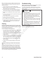
Maintenance
Before performing any maintenance procedures, read Safety.
Scheduled maintenance prevents unexpected downtime,
reduces the number of accidents due to poor equipment per-
formance and helps extend the life of the light tower.
Proper maintenance and care of your light tower and trailer
is a must for safe and reliable operation. Use the following
maintenance and care guidelines in addition to those sched-
uled by your shop equipment maintenance schedule.
Where equipment is operated under severe conditions (very
dusty, extreme heat or cold, etc.), affected items should be
serviced more frequently.
Engine
Refer to the Engine Operator’s Manual for all engine sched-
uled maintenance procedures.
Changing and Adding Engine Oil
Use a high - quality engine oil of API (American Petroleum
Institute) service class CG-4/CH-4/CI-4. Refer to the Engine
Operator’s Manual for detailed engine oil specifications and
service procedures.
All models are equipped with remote oil drains.
Engine Filters
Refer to the Engine Operator’s Manual for air, oil and fuel fil-
ter service procedures.
Electrical System
Generator
Refer to the Generator Operator’s Manual for all generator
schedule maintenance procedures.
Ballast Panel
The ballast panels are located on the front of the light tower
trailer. The ballast panels can be accessed by opening the
doors and removing the ballast covers. Each ballast panel
contains two tower light lamp ballast (A, Figure 25) and
capacitors (B). For additional wiring information, refer to the
separate Wire Schematic Manual.
DANGER
Electrocution Hazard
• Only qualified electricians should service or perform
replacement procedures. Ballast and capacitors are
capable of discharging high voltage. Always use
appropriate personal safety clothing and gear when
servicing electrical components.
• High voltage is present when engine is running. Never
attempt to service electrical components while engine
is running.
• Do not operate the light tower if the insulation on the
electrical wiring is cut or worn, or if bare wires are
exposed. Repair or replace damaged wiring before
starting the engine.

Not for
Reproduction
20
www.allmand.com
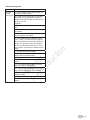
Hydraulic Pump
Hydraulic Oil Specifications
Recommended Hydraulic Fluids
Ambient Temperature
USE LONG LIFE SYNTHETIC HYDRAULIC FLUID
SUCH AS PENTOCIN CHF 11S
USE AUTOMATIC
TRANSMISSION FLUID
Adding Hydraulic Oil
Fill the reservoir (Figure 26) with automatic transmission fluid
or any clean hydraulic fluid having a viscosity index that is
suitable for the climate conditions in which the unit will be
operated. Refer to the preceding table.
NOTE: Standard units are supplied with automatic transmis-
sion fluid (ATF), and arctic units are supplied with long life
synthetic hydraulic fluid.
Priming the Hydraulic Pump
Pumps that have been disassembled for repair, or pumps
that have been replaced require proper priming to avoid pos-
sible pump failure. A pump is said to be “primed” when the
internal portions of the pump are filled with oil and all air has
been expelled. To prime the pump:
1. Make sure that the oil reservoir (A, Figure 26) is filled
with oil to the full mark.
2. Place a catch pan under the pump to catch excess oil.
3. Loosen the hose end (B, Figure 26) to allow oil and air to
escape.
4. Turn on the ignition switch and move the tower raise /
lower switch to the “raise” or up position. Do so inter-
mittently, or “jog” the pump. This will expel air and oil
through the loosened fitting. Repeat until oil flow is free
of air.
5. Re-tighten the hose end. Turn off the ignition switch.
6. Remove the catch pan and dispose of the oil following
the guidelines of governmental agencies.
7. Replenish the oil in the reservoir to the full mark.
Once the pump has been primed, the cylinder should be
purged of air. To purge the cylinder of air:
1. Make sure that the oil reservoir is filled with oil to the full
mark.
2. Clean the bleeder fitting (A, Figure 27) on the upper end
of the cylinder barrel.
3. Place a bleeder hose over the end of the bleeder fitting.
Place the other end of the bleeder hose in a suitable
catch container.
4. Turn on the ignition switch and move the tower raise /
lower switch to the “raise” or up position.
5. Open the bleeder fitting. Allow oil and air to bleed out of
the cylinder. Close the bleeder when oil flow is free of air.
6. Remove the catch container and the bleeder hose.
Dispose of the oil in the catch container following the
guidelines of governmental agencies.
7. Move the tower raise / lower switch to the “lower” or down
position. Be sure that the tower is fully lowered. Turn off
the ignition switch.
8. Replenish the oil in the reservoir to the full mark.
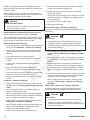
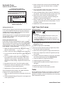
Light Tower And Lamps
Changing Lamps
WARNING
Burn Hazard
• The light fixtures become extremely hot during use.
• Always use caution and heat–resistant glove when
handling the lights or allow the lights to sufficiency cool
down before handling.
1. Turn off the lights and shut off the engine. Allow the bulbs
and fixtures to cool.
2. Lower the light tower to full DOWN.
3. Loosen the lens channel screws (E, Figure 28) to allow
the removal of the lens channel (F).
4. Remove the silicone gasket (G, Figure 28) and lens (H).
5. Remove the support clip screws (A, Figure 28) and sup-
port clip (B).
6. Carefully remove the old lamp (C, Figure 28), and install
the correct replacement lamp. See Specifications.
7. Clean the reflector (D, Figure 28) and lens.
8. Install the support clip and screws.
9. Install the silicone gasket and lens. Replace if worn or
damaged.
10. Install the lens channel and screws.
11. Test the new lamp to ensure proper operation.
Trailer
Proper maintenance and care of your trailer is a must for safe
and reliable operation. Follow these maintenance and care
guidelines in addition to those scheduled by your shop equip-
ment maintenance schedule.
La page est en cours de chargement...
La page est en cours de chargement...
La page est en cours de chargement...
La page est en cours de chargement...
La page est en cours de chargement...
La page est en cours de chargement...
La page est en cours de chargement...
La page est en cours de chargement...
La page est en cours de chargement...
La page est en cours de chargement...
La page est en cours de chargement...
La page est en cours de chargement...
La page est en cours de chargement...
La page est en cours de chargement...
La page est en cours de chargement...
La page est en cours de chargement...
La page est en cours de chargement...
La page est en cours de chargement...
La page est en cours de chargement...
La page est en cours de chargement...
La page est en cours de chargement...
La page est en cours de chargement...
La page est en cours de chargement...
La page est en cours de chargement...
La page est en cours de chargement...
La page est en cours de chargement...
La page est en cours de chargement...
La page est en cours de chargement...
La page est en cours de chargement...
La page est en cours de chargement...
La page est en cours de chargement...
La page est en cours de chargement...
La page est en cours de chargement...
La page est en cours de chargement...
La page est en cours de chargement...
La page est en cours de chargement...
La page est en cours de chargement...
La page est en cours de chargement...
La page est en cours de chargement...
La page est en cours de chargement...
La page est en cours de chargement...
La page est en cours de chargement...
La page est en cours de chargement...
La page est en cours de chargement...
La page est en cours de chargement...
La page est en cours de chargement...
La page est en cours de chargement...
La page est en cours de chargement...
La page est en cours de chargement...
La page est en cours de chargement...
La page est en cours de chargement...
La page est en cours de chargement...
La page est en cours de chargement...
La page est en cours de chargement...
La page est en cours de chargement...
La page est en cours de chargement...
La page est en cours de chargement...
La page est en cours de chargement...
La page est en cours de chargement...
La page est en cours de chargement...
-
 1
1
-
 2
2
-
 3
3
-
 4
4
-
 5
5
-
 6
6
-
 7
7
-
 8
8
-
 9
9
-
 10
10
-
 11
11
-
 12
12
-
 13
13
-
 14
14
-
 15
15
-
 16
16
-
 17
17
-
 18
18
-
 19
19
-
 20
20
-
 21
21
-
 22
22
-
 23
23
-
 24
24
-
 25
25
-
 26
26
-
 27
27
-
 28
28
-
 29
29
-
 30
30
-
 31
31
-
 32
32
-
 33
33
-
 34
34
-
 35
35
-
 36
36
-
 37
37
-
 38
38
-
 39
39
-
 40
40
-
 41
41
-
 42
42
-
 43
43
-
 44
44
-
 45
45
-
 46
46
-
 47
47
-
 48
48
-
 49
49
-
 50
50
-
 51
51
-
 52
52
-
 53
53
-
 54
54
-
 55
55
-
 56
56
-
 57
57
-
 58
58
-
 59
59
-
 60
60
-
 61
61
-
 62
62
-
 63
63
-
 64
64
-
 65
65
-
 66
66
-
 67
67
-
 68
68
-
 69
69
-
 70
70
-
 71
71
-
 72
72
-
 73
73
-
 74
74
-
 75
75
-
 76
76
-
 77
77
-
 78
78
-
 79
79
-
 80
80


Simplicity LIGHT TOWER, NIGHT-LITE PRO II, CE Manuel utilisateur
- Taper
- Manuel utilisateur
- Ce manuel convient également à
dans d''autres langues
Documents connexes
Autres documents
-
Allmand NL Pro II Le manuel du propriétaire
-
-
-
-
-
 Bully CR007D Manuel utilisateur
-
-
 Four winns Fling Le manuel du propriétaire
-
Wacker Neuson LTW20Z3 Manuel utilisateur
-
Wacker Neuson LTW6K Manuel utilisateur

