Faber Levante G 24 SS 300 cfm Le manuel du propriétaire
- Catégorie
- Hottes
- Taper
- Le manuel du propriétaire
Ce manuel convient également à

LEVG24SS300
LEVG30SS300
Installation Instructions
Use and Care Information
Instructions d'installation
Utilisez et d'entretien
Instrucciones de instalación
Información de uso y cuidado
LEVANTE G

2
CONTENTS
Section Page
Important safety instructions 3
Range hood dimensions 6
Installation height requirements 7
Parts 8
Tools needed 9
Before installation remove shipping materials 10
Only for Canadian market 11
Choose vertical or horizontal electrical connection knockout'sChoose vertical or horizontal electrical connection knockout's 12
Venting method options-ducted or ductless 14
Non ducted recirculation option 15
Ducted - 7" round outlet 16
Ducted - 3 1/4" x 10" rectangular outlet on top
18
Ducted - 3 1/4" x 10" rectangular outlet rear
19
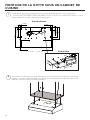
Choosing the mounting method
20
Mounting range hood on wall
21
Mounting range hood under the cabinet
25
Connecting electricity
27
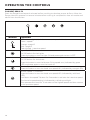
Operating the controls
28
Caring for lters
29
Replacing lighting
31
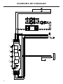
Wiring diagram
32
Warranty
33

3
IMPORTANT SAFETY INSTRUCTIONS
READ AND SAVE THESE INSTRUCTIONS BEFORE YOU START
INSTALLING THIS RANGE HOOD
WARNING: - TO REDUCE THE RISK OF A RANGE TOP GREASE FIRE:
a) Never leave surface units unattended at high settings. Boilovers cause smoking and
greasy spillovers that may ignite. Heat oils slowly on low or medium setting.
b) Always turn hood ON when cooking at high heat or when ambeing food (i.e. Crepes
Suzette, Cherries Jubilee, Peppercorn Beef Flambé).
c) Clean ventilating fans frequently. Grease should not be allowed to accumulate on fan or
lter.
d) Use proper pan size. Always use cookware appropriate for the size of the surface element.
WARNING: - TO REDUCE THE RISK OF INJURY TO PERSONS IN THE EVENT OF A RANGE
TOP GREASE FIRE, OBSERVE THE FOLLOWING*:
a) SMOTHER FLAMES with a close-tting lid, cookie sheet, or metal tray, then turn off the
burner. BE CAREFUL TO PREVENT BURNS. If the ames do not go out immediately
EVACUATE AND CALL THE FIRE DEPARTMENT.
b) NEVER PICK UP A FLAMING PAN - You may be burned.
c) DO NOT USE WATER, including wet dishcloths or towels - a violent steam explosion will
result.
d) Use an extinguisher ONLY if:
1. You know you have a Class ABC extinguisher, and you already know how to operate
it.
2. The re is small and contained in the area where it started.
3. The re department is being called.
4. You can ght the re with your back to an exit.
* Based on "Kitchen Firesafety Tips" published by NFPA
WARNING - TO REDUCE THE RISK OF FIRE OR ELECTRIC SHOCK, do not use this fan with
any solid-state speed control device.
WARNING - TO REDUCE THE RISK OF FIRE, ELECTRICAL SHOCK, OR INJURY TO PERSONS,
OBSERVE THE FOLLOWING:
1. Use this unit only in the manner intended by the manufacturer. If you have any questions,
contact the manufacturer.
2. Before servicing or cleaning unit, switch power off at service panel and lock the service
disconnecting means to prevent power from being switched on accidentally. When the
service disconnecting means cannot be locked, securely fasten a prominent warning
device, such as a tag, to the service panel.
CAUTION: For General Ventilating Use Only. Do Not Use To Exhaust Hazardous or Explo-
sive Materials and Vapors.
WARNING - TO REDUCE THE RISK OF FIRE, ELECTRICAL SHOCK, OR INJURY TO PERSONS,
OBSERVE THE FOLLOWING:
1. Installation Work And Electrical Wiring Must Be Done By Qualied Person(s) In Accor-
dance With All Applicable Codes And Standards, Including Fire-Rated Construction.
2. Sufcient air is needed for proper combustion and exhausting of gases through the
ue (chimney) of fuel burning equipment to prevent backdrafting. Follow the heating
equipment manufacturer's guideline and safety standards such as those published by
the National Fire Protection Association (NFPA), and the American Society for Heating,
Refrigeration and Air Conditioning Engineers (ASHRAE), and the local code authorities.

4
ALL WALL AND FLOOR OPENINGS WHERE THE RANGE HOOD IS INSTALLED
MUST BE SEALED.
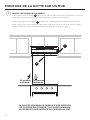
This Range Hood requires at least 24" of clearance between the bottom of the Range
Hood and the cooking surface or countertop. This hood has been approved by UL at this
distance from the cooktop.
This minimum clearance may be higher depending on local building codes. For gas cooktops
and combination ranges, a minimum of 30" is recommended and may be required.
Overhead cabinets on both sides of this unit must be a minimum of 18" above the cooking
surface or countertop. Consult the cooktop or range installation instructions given by the
manufacturer before making any cutouts.
MOBILE HOME INSTALLATION The installation of this Range Hood must conform to the
Manufactured Home Construction and Safety Standards, Title 24 CFR, Part 3280 (formerly
Federal Standard for Mobile Home Construction and Safety, Title 24, HUD, Part 280). See
Electrical Requirements"
• Venting system MUST terminate outside the home.
• DO NOT terminate the ductwork in an attic or other enclosed space.
• DO NOT use 4" laundry-type wall caps.
• Flexible-type ductwork is not recommended.
• DO NOT obstruct the ow of combustion and ventilation air.
• Failure to follow venting requirements may result in a re.
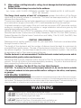
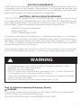
WARNING
!
VENTING REQUIREMENTS
Determine which venting method is best for your application. Ductwork can extend either
through the wall or the roof.
The length of the ductwork and the number of elbows should be kept to a minimum to
provide efcient performance. The size of the ductwork should be uniform. Do not install
two elbows together. Use duct tape to seal all joints in the ductwork system. Use caulking
to seal exterior wall or oor opening around the cap.
Flexible ductwork is not recommended. Flexible ductwork creates back pressure and air
turbulence that greatly reduces performance.
Make sure there is proper clearance within the wall or oor for exhaust duct before making
cutouts. Do not cut a joist or stud unless absolutely necessary. If a joist or stud must be cut,
then a supporting frame must be constructed.
WARNING - To Reduce The Risk Of Fire, Use Only Metal Ductwork.
CAUTION - To reduce risk of re and to properly exhaust air, be sure to duct air outside
– Do not vent exhaust air into spaces within walls or ceilings or into attics, crawl spaces,
or garages.
Cold Weather installations
An additional back draft damper should be installed to minimize backward cold air ow and a nonme-
tallic thermal break should be installed to minimize conduction of outside temperatures as part of the
vent system. The damper should be on the cold air side of the thermal break. The break should be as
close as possible to where the vent system enters the heated portion of the house.
3. When cutting or drilling into wall or ceiling, do not damage electrical wiring and other
hidden utilities.
4. Ducted fans must always be vented to the outdoors.

5
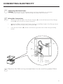
ELECTRICAL REQUIREMENTS
A 120 volt, 60 Hz AC-only electrical supply is required on a separate 15 amp fused circuit.
A time-delay fuse or circuit breaker is recommended. The fuse must be sized per local
codes in accordance with the electrical rating of this unit as specied on the serial/rating
plate located inside the unit near the eld wiring compartment.
ELECTRICAL INSTALLATION WITH WIRING BOX
THIS UNIT MUST BE CONNECTED WITH COPPER WIRE ONLY. Wire sizes must conform
to the requirements of the National Electrical Code, ANSI/NFPA 70 - latest edition, and all
local codes and ordinances. Wire size and connections must conform with the rating of
the appliance. Copies of the standard listed above may be obtained from:
National Fire Protection Association
Batterymarch Park
Quincy, Massachusetts 02269
This appliance should be connected directly to the fused disconnect (or circuit breaker)
through exible, armored or nonmetallic sheathed copper cable. Allow some slack in
the cable so the appliance can be moved if servicing is ever necessary. A UL Listed,
1/2" conduit connector must be provided at each end of the power supply cable (at
the appliance and at the junction box).
When making the electrical connection, cut a 1 1/4" hole in the wall. A hole cut through
wood must be sanded until smooth. A hole through metal must have a grommet.
• Electrical ground is required on this Range Hood.
• If cold water pipe is interrupted by plastic, nonmetallic gaskets or other
materials, DO NOT use for grounding.
• DO NOT ground to a gas pipe.
• DO NOT have a fuse in the neutral or grounding circuit. A fuse in the neutral
or grounding circuit could result in electrical shock.
• Check with a qualied electrician if you are in doubt as to whether the Range
Hood is properly grounded.
• Failure to follow electrical requirements may result in a re.
WARNING
!
State of California Proposition 65 Warning (US only)
WARNING
This product contains chemicals known to the State of California to cause cancer
and birth defects or other reproductive harm.
For more information go to www.P65Warnings.ca.gov

6
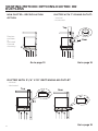
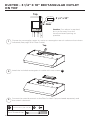
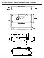
RANGE HOOD DIMENSIONS
7 1/4
3
23 15/16” - 29 15/16” - 35 15/16”
7
1/4
3
23 15/16” - 29 15/16” - 35 15/16”
24" 30"
24"
30"
DRAFT 07-JUL-2020 06:22

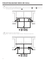
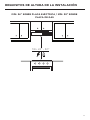
7
MIN. 24" OVER ELECTRIC / MIN. 30" OVER GAS
INSTALLATION HEIGHT REQUIREMENTS
Min. 24" - 30"

8
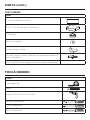
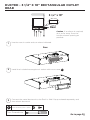
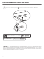
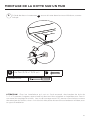
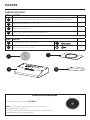
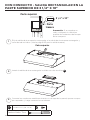
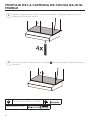
PARTS
REF. PART
A
Hood body – Includes Controls, Light, Filters, Blower 1
B
Damper (3 1/4" x 10") 1
C
7" Round Flange 1
D
Grid (Only for Canadian Market) 1
REF
PART
E
Pozi Screws (3/16" x 1 15/16")
4
F
Torx Screws (1/8" x 3/8")
4
PARTS INCLUDED
C
B
A
D
Available Accessories
Activated Charcoal Filter (FILTER5)
Note: The Charcoal Filter is attached with two screws
(See page 15 and Figure C).
The Charcoal Filters must be purchased with only Faber
authorized dealers.

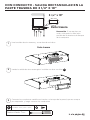
9
PARTS NEEDED
PARTS (cont.)
PART
7" Round Metal Ductwork
3 1/4" x 10" Rectangular Ductwork
7" Damper
Wire connectors.
Power Supply Cable.
-
Drywall plugs or other suitable wall fasteners based on
your installation.
Wall Cap/Roof Cap Needs to be purchased separately
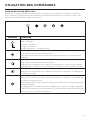
TOOLS NEEDED
TOOL
Tape Measure
Pencil
Electric Drill with 5/16" Drill Bit
Phillips Screwdriver
Torx Screwdriver
Pozi Screwdriver

10
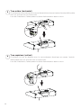
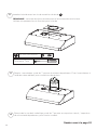
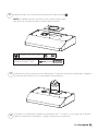
BEFORE INSTALLATION REMOVE SHIPPING
MATERIALS
Remove the side packaging.
Remove the foam packaging and wood bar.
1
2
3
Ready for Installation.
Caution: Do not
pick up hood using
the wood bar

11
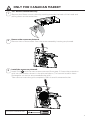
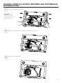
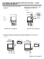
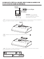
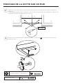
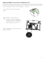
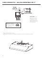
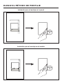
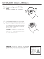
ONLY FOR CANADIAN MARKET
1
2
For ducted installations only:
Remove the lters one at a time by pushing towards the back of the hood and
pulling down at the same time.
Install the screws as pictured.
Install Grid
D
with the two screws removed from step 2. Screw the protection
grid into the location shown in the picture below. (The correct location has a
rectangular cut out to accommodate the grid.)
Take care to screw the grid completely ush to avoid unwanted noise.
Remove the screws as pictured.
Remove two of the screws from the motor assembly housing as pictured.
3
Phillips Screwdriver
D

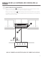
12
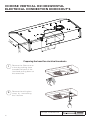
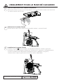
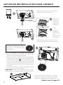
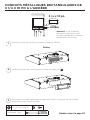
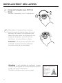
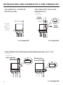
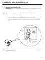
Remove the lters one at
a time by pushing them
towards the back of the
hood and pulling down at
the same time.
Remove the wiring box
cover by unscrewing
the 2 screws.
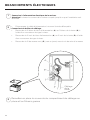
Preparing the hood for electrical knockouts
7" 1/2
13/16"
13/16"
Created by
Palazzi, Walter
Denomination
GENERAL ASSEMBLY
Lang EN
Sheet
3
/3
Modif.by
Astolfi, Ilaria
Approved by
Approval date
Doc. status
Drawing N.
02B_710
Rev
01
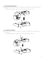
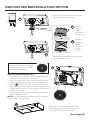
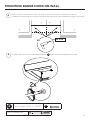
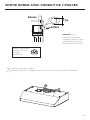
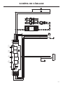
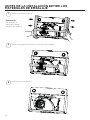
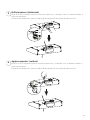
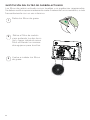
CHOOSE VERTICAL OR HORIZONTAL
ELECTRICAL CONNECTION KNOCKOUT'S
1
2
Phillips Screwdriver

13
Rear Hole (Horizontal)
Choose the rear hole for the electric connection and break with a screwdriver or other
tool.
During the installation thread Power Supply Cable through this hole.
3
Top Hole (Vertical)
Choose the top hole for the electric connection and break with a screwdriver or
other tool.
During the installation thread Power Supply Cable through this hole.
4

14
VENTING METHOD OPTIONS-DUCTED OR
DUCTLESS
DUCTED WITH 7" ROUND OUTLET:
– Vertical
– Horizontal
7"
Rear
Top
10"
3 1/4"
10"
3 1/4"
Rear
Top
Go to page 16Go to page 15
Go to page 18
DUCTED WITH 3 1/4" X 10" RECTANGULAR OUTLET
– Vertical
– Horizontal
NON DUCTED - RECIRCULATION
OPTION
Requires
purchase
of
Activated
Charcoal
Accessory

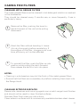
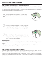
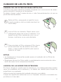
15
b1
a
b2
Remove the indicated blower cover
(do not discard the screw).
Reinstall the existing Grease Filters
after installing the Activated Charcoal
Filter before operating hood.
Reinstall the modied blower cover
with the same screw.
Cut the
cover
where
indicated in
picture b1.
Discard /
Recycle
upper
pieces of
blower
cover.
d
b3
NON DUCTED RECIRCULATION OPTION
Go to page 20
Required Activated Charcoal
Filter Accessory - (FILTER5)
purchased separately.
c
Non Ducted installations only:
1. Remove the two screws located on the motor
housing in the location indicated.
2. Place the charcoal lter with the tabs against
the blower housing in the location indicated on
gure
c
. The front side of the FILTER5 will
have the keyhole mounting on the top surface
of the lter. A layer of charcoal will be visible
through the grills.
3. Use the two screws removed earlier to attach
the FILTER5 in place.
NOTE: For Non ducted installations the Canadian
Grid should NOT be used.

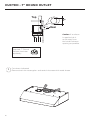
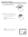
16
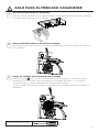
DUCTED - 7" ROUND OUTLET
Cut where indicated.
Remove both the rectangular and semicircle areas with metal shears.
Rear
Top
7"
Required; 7" Round
Damper purchase
separately.
1
Caution: If an elbow
is required, do it
as far away from
the hood's exhaust
opening as possible.

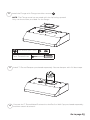
17
Install the Flange with Flange transition screws
F
.
Install 7" Round Damper purchased separately. Secure damper with foil duct tape.
Connect the 7" Round Metal Ductwork to the Roof or Wall Cap purchased separately
and then attach ductwork.
2
3
Torx Screwdriver
NOTE: The Flange must be mounted with the lip facing upward.
Only use the screws provided for the ange
F
Torx Screws (1/8" x 3/8")
4
Go to page 20

18
Choose the rectangular upper air outlet or rectangular rear air outlet and cut where
indicated.(See page 19 for Rear Outlet)
Install the included rectangular air outlet with two screws
F
.
Connect the metal ductwork to the Roof or Wall Cap purchased separately and
then attach ductwork.
Rear
Top
Top
3 1/4" x 10"
DUCTED - 3 1/4" X 10" RECTANGULAR OUTLET
ON TOP
1
2
3
Torx Screwdriver
F
Torx Screws (1/8" x 3/8")
Caution: If an elbow is required,
do it as far away from the
hood's exhaust opening as
possible.

19
Go to page 20
Rear
Rear
3 1/4" x 10"
Use the rear air outlet and cut where indicated.
Install the included rectangular air outlet with two screws
F
.
1
2
Torx Screwdriver
F
Torx Screws (1/8" x 3/8")
DUCTED - 3 1/4" X 10" RECTANGULAR OUTLET
REAR
Caution: If an elbow is required,
do it as far away from the
hood's exhaust opening as
possible.
Connect the metal ductwork to the Roof or Wall Cap purchased separately and
then attach ductwork.
3

20
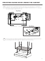
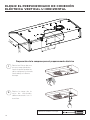
CHOOSING THE MOUNTING METHOD
Installation for Mounting on the Wall
Installation for Mounting to the cabinet
Page
21
Page
25
La page est en cours de chargement...
La page est en cours de chargement...
La page est en cours de chargement...
La page est en cours de chargement...
La page est en cours de chargement...
La page est en cours de chargement...
La page est en cours de chargement...
La page est en cours de chargement...
La page est en cours de chargement...
La page est en cours de chargement...
La page est en cours de chargement...
La page est en cours de chargement...
La page est en cours de chargement...
La page est en cours de chargement...
La page est en cours de chargement...
La page est en cours de chargement...
La page est en cours de chargement...
La page est en cours de chargement...
La page est en cours de chargement...
La page est en cours de chargement...
La page est en cours de chargement...
La page est en cours de chargement...
La page est en cours de chargement...
La page est en cours de chargement...
La page est en cours de chargement...
La page est en cours de chargement...
La page est en cours de chargement...
La page est en cours de chargement...
La page est en cours de chargement...
La page est en cours de chargement...
La page est en cours de chargement...
La page est en cours de chargement...
La page est en cours de chargement...
La page est en cours de chargement...
La page est en cours de chargement...
La page est en cours de chargement...
La page est en cours de chargement...
La page est en cours de chargement...
La page est en cours de chargement...
La page est en cours de chargement...
La page est en cours de chargement...
La page est en cours de chargement...
La page est en cours de chargement...
La page est en cours de chargement...
La page est en cours de chargement...
La page est en cours de chargement...
La page est en cours de chargement...
La page est en cours de chargement...
La page est en cours de chargement...
La page est en cours de chargement...
La page est en cours de chargement...
La page est en cours de chargement...
La page est en cours de chargement...
La page est en cours de chargement...
La page est en cours de chargement...
La page est en cours de chargement...
La page est en cours de chargement...
La page est en cours de chargement...
La page est en cours de chargement...
La page est en cours de chargement...
La page est en cours de chargement...
La page est en cours de chargement...
La page est en cours de chargement...
La page est en cours de chargement...
La page est en cours de chargement...
La page est en cours de chargement...
La page est en cours de chargement...
La page est en cours de chargement...
La page est en cours de chargement...
La page est en cours de chargement...
La page est en cours de chargement...
La page est en cours de chargement...
La page est en cours de chargement...
La page est en cours de chargement...
La page est en cours de chargement...
La page est en cours de chargement...
La page est en cours de chargement...
La page est en cours de chargement...
La page est en cours de chargement...
La page est en cours de chargement...
-
 1
1
-
 2
2
-
 3
3
-
 4
4
-
 5
5
-
 6
6
-
 7
7
-
 8
8
-
 9
9
-
 10
10
-
 11
11
-
 12
12
-
 13
13
-
 14
14
-
 15
15
-
 16
16
-
 17
17
-
 18
18
-
 19
19
-
 20
20
-
 21
21
-
 22
22
-
 23
23
-
 24
24
-
 25
25
-
 26
26
-
 27
27
-
 28
28
-
 29
29
-
 30
30
-
 31
31
-
 32
32
-
 33
33
-
 34
34
-
 35
35
-
 36
36
-
 37
37
-
 38
38
-
 39
39
-
 40
40
-
 41
41
-
 42
42
-
 43
43
-
 44
44
-
 45
45
-
 46
46
-
 47
47
-
 48
48
-
 49
49
-
 50
50
-
 51
51
-
 52
52
-
 53
53
-
 54
54
-
 55
55
-
 56
56
-
 57
57
-
 58
58
-
 59
59
-
 60
60
-
 61
61
-
 62
62
-
 63
63
-
 64
64
-
 65
65
-
 66
66
-
 67
67
-
 68
68
-
 69
69
-
 70
70
-
 71
71
-
 72
72
-
 73
73
-
 74
74
-
 75
75
-
 76
76
-
 77
77
-
 78
78
-
 79
79
-
 80
80
-
 81
81
-
 82
82
-
 83
83
-
 84
84
-
 85
85
-
 86
86
-
 87
87
-
 88
88
-
 89
89
-
 90
90
-
 91
91
-
 92
92
-
 93
93
-
 94
94
-
 95
95
-
 96
96
-
 97
97
-
 98
98
-
 99
99
-
 100
100


Faber Levante G 24 SS 300 cfm Le manuel du propriétaire
- Catégorie
- Hottes
- Taper
- Le manuel du propriétaire
- Ce manuel convient également à
dans d''autres langues
Documents connexes
-
Faber LEVN24SS300 Manuel utilisateur
-
-
-
-
Faber Levante I 30 SS 300 cfm Guide d'installation
-
-
-
-
-