La page est en cours de chargement...

Publication 1794-IN019E-EN-P - May 2009
Installation Instructions
FLEX I/O 8 Relay Output Module
Cat. No. 1794-OW8, 1794-OW8K, 1794-OW8XT
(Modules with a K in the last position of the catalog number are
conformally coated to meet noxious gas requirements of ISA/ANSI-71.040
1985 Class G3 Environment.)
European Hazardous Location Approval
The 1794-OW8, 1794-OW8K, 1794-OW8XT modules are European Zone 2
approved.
Important User Information
Solid state equipment has operational characteristics differing from those of electromechanical equipment.
Safety Guidelines for the Application, Installation and Maintenance of Solid State Controls (Publication
SGI-1.1 available from your local Rockwell Automation sales office or online at
http://www.literature.rockwellautomation.com) describes some important differences between solid state
equipment and hard-wired electromechanical devices. Because of this difference, and also because of the
wide variety of uses for solid state equipment, all persons responsible for applying this equipment must
satisfy themselves that each intended application of this equipment is acceptable.
In no event will Rockwell Automation, Inc. be responsible or liable for indirect or consequential damages
resulting from the use or application of this equipment.
The examples and diagrams in this manual are included solely for illustrative purposes. Because of the many
variables and requirements associated with any particular installation, Rockwell Automation, Inc. cannot
assume responsibility or liability for actual use based on the examples and diagrams.
No patent liability is assumed by Rockwell Automation, Inc. with respect to use of information, circuits,
equipment, or software described in this manual.
Reproduction of the contents of this manual, in whole or in part, without written permission of Rockwell
Automation, Inc. is prohibited.
Throughout this manual we use notes to make you aware of safety considerations.
WARNING
Identifies information about practices or circumstances that can cause an
explosion in a hazardous environment, which may lead to personal injury or
death, property damage, or economic loss.
IMPORTANT
Identifies information that is critical for successful application and understanding
of the product.
ATTENTION
Identifies information about practices or circumstances that can lead to personal
injury or death, property damage, or economic loss. Attentions help you identify a
hazard, avoid a hazard, or recognize the consequence
ATTENTION
Environment and Enclosure
This equipment is intended for use in a Pollution Degree 2 industrial
environment, in overvoltage Category II applications (as defined in IEC 60664-1),
at altitudes up to 2000 m (6562 ft) without derating.
This equipment is considered Group 1, Class A industrial equipment according
to IEC/CISPR 11. Without appropriate precautions, there may be difficulties with
electromagnetic compatibility in residential and other environments due to
conducted and radiated disturbances.
This equipment is supplied as open-type equipment. It must be mounted within
an enclosure that is suitably designed for those specific environmental
conditions that will be present and appropriately designed to prevent personal
injury resulting from accessibility to live parts. The enclosure must have suitable
flame-retardant properties to prevent or minimize the spread of flame,
complying with a flame spread rating of 5VA, V2, V1, V0 (or equivalent) if
non-metallic. The interior of the enclosure must be accessible only by the use of
a tool. Subsequent sections of this publication may contain additional
information regarding specific enclosure type ratings that are required to comply
with certain product safety certifications.
In addition to this publication, see:
• Industrial Automation Wiring and Grounding Guidelines, for additional
installation requirements, Allen-Bradley publication 1770-4.1
.
• NEMA Standards 250 and IEC 60529, as applicable, for explanations of
the degrees of protection provided by different types of enclosure.
WARNING
When you insert or remove the module while backplane power is on, an
electrical arc can occur. This could cause an explosion in hazardous location
installations. Be sure that power is removed or the area is nonhazardous
before proceeding.
ATTENTION
FLEX I/O is grounded through the DIN rail to chassis ground. Use zinc plated
yellow-chromate steel DIN rail to assure proper grounding. The use of other
DIN rail materials (for example, aluminum or plastic) that can corrode, oxidize,
or are poor conductors, can result in improper or intermittent grounding. Secure
DIN rail to mounting surface approximately every 200 mm (7.8 in.) and use
end-anchors appropriately.
ATTENTION
Preventing Electrostatic Discharge
This equipment is sensitive to electrostatic discharge, which can cause internal
damage and affect normal operation. Follow these guidelines when you handle
this equipment:
• Touch a grounded object to discharge potential static.
• Wear an approved grounding wriststrap.
• Do not touch connectors or pins on component boards.
• Do not touch circuit components inside the equipment.
• Use a static-safe workstation, if available.
• Store the equipment in appropriate static-safe packaging when not in
use.
WARNING
If you connect or disconnect wiring while the field-side power is on, an
electrical arc can occur. This could cause an explosion in hazardous location
installations. Be sure that power is removed or the area is nonhazardous
before proceeding.
ATTENTION
Personnel responsible for the application of safety-related programmable
electronic systems (PES) shall be aware of the safety requirements in the
application of the system and shall be trained in using the system.
ATTENTION
Do not remove or replace a Terminal Base unit while power is applied.
Interruption of the backplane can result in unintentional operation or machine
motion.
ATTENTION
To comply with the CE Low Voltage Directive (LVD), this equipment must be
powered from a source compliant with the following:
Safety Extra Low Voltage (SELV) or Protected Extra Low Voltage (PELV).
European Zone 2 Certification (The following applies when the product bears the Ex
or EEx Marking)
This equipment is intended for use in potentially explosive atmospheres as defined by European
Union Directive 94/9/EC and has been found to comply with the Essential Health and Safety
Requirements relating to the design and construction of Category 3 equipment intended for use
in potentially explosive atmospheres, given in Annex II to this Directive.
Compliance with the Essential Health and Safety Requirements has been assured by compliance
with EN 60079-15 and EN 60079-0.
WARNING
Observe the following additional Zone 2 certification requirements.
• This equipment is not resistant to sunlight or other sources of UV
radiation.
• This equipment must be installed in an enclosure providing at least IP54
protection when applied in Zone 2 environments.
• This equipment shall be used within its specified ratings defined by
Allen-Bradley.
• Provision shall be made to prevent the rated voltage from being
exceeded by transient disturbances of more than 40% when applied in
Zone 2 environments.
• This equipment must be used only with ATEX certified backplanes.
• Secure any external connections that mate to this equipment by using
screws, sliding latches, threaded connectors, or other means provided
with this product.
• Do not disconnect equipment unless power has been removed or the
area is known to be nonhazardous.

2 FLEX I/O 8 Relay Output Module
Publication 1794-IN019E-EN-P - May 2009
North American Hazardous Location Approval
The 1794-OW8, 1794-OW8K, 1794-OW8XT modules are Hazardous
Location approved.
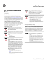
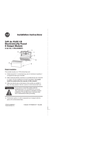
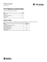
Installing Your Relay Output Module
The module mounts on a 1794 terminal base.
1. Rotate the keyswitch (1) on the terminal base (2) clockwise to
position 9 as required for this type of module.
2. Make certain the flexbus connector (3) is pushed all the way to the
left to connect with the neighboring termbase/adapter. You
cannot install the module unless the connector is fully
extended.
3. Make sure the pins on the bottom of the module are straight so
they will align properly with the connector in the terminal base.
4. Position the module (4) with its alignment bar (5) aligned with the
groove (6) on the terminal base.
5. Press firmly and evenly to seat the module in the terminal base
unit. The module is seated when the latching mechanism (7) is
locked into the module.
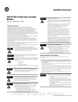
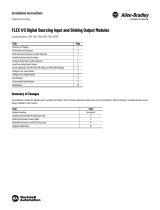
Simplified Schematic of the Relay Module
Load power can be obtained from a variety of sources, and can range from
+5V to 240V AC. Make certain that only 24V DC is applied to the module
power terminals on the module terminal base unit.
If you are using 220/240V AC power, you must use the 1794-TBN or -TBNF
terminal base unit. Maximum voltage allowed is shown below.
Working Voltage and Isolation Voltage Ratings
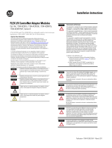
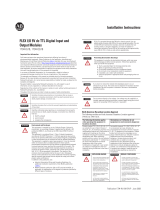
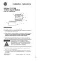
Wiring to a 1794-TB2, -TB3 or -TB3S Terminal Base Unit
1. Connect individual output relay contact (customer load) wiring to
numbered terminals on the 0-15 row (A) as indicated in the table
below. The even numbered terminals are one pole of the relay
contacts; the odd numbered terminals are the other pole of the
relay contacts.
2. Connect 24V DC return to terminal 16 on the 16-33 row (B).
3. Connect +24V DC power to terminal 34 on the 34-51 row (C).
The following information applies when operating this
equipment in hazardous locations:
Informations sur l’utilisation de cet équipement en
environnements dangereux :
Products marked “CL I, DIV 2, GP A, B, C, D” are suitable for
use in Class I Division 2 Groups A, B, C, D, Hazardous
Locations and nonhazardous locations only. Each product is
supplied with markings on the rating nameplate indicating the
hazardous location temperature code. When combining
products within a system, the most adverse temperature code
(lowest “T” number) may be used to help determine the
overall temperature code of the system. Combinations of
equipment in your system are subject to investigation by the
local Authority Having Jurisdiction at the time of installation.
Les produits marqués "CL I, DIV 2, GP A, B, C, D" ne conviennent
qu’à une utilisation en environnements de Classe I Division 2
Groupes A, B, C, D dangereux et non dangereux. Chaque produit
est livré avec des marquages sur sa plaque d’identification qui
indiquent le code de température pour les environnements
dangereux. Lorsque plusieurs produits sont combinés dans un
système, le code de température le plus défavorable (code de
température le plus faible) peut être utilisé pour déterminer le
code de température global du système. Les combinaisons
d’équipements dans le système sont sujettes à inspection par
les autorités locales qualifiées au moment de l’installation.
WARNING
EXPLOSION HAZARD
• Do not disconnect equipment
unless power has been removed or
the area is known to be
nonhazardous.
• Do not disconnect connections to
this equipment unless power has
been removed or the area is known
to be nonhazardous. Secure any
external connections that mate to
this equipment by using screws,
sliding latches, threaded
connectors, or other means
provided with this product.
• Substitution of components may
impair suitability for Class I,
Division 2.
• If this product contains batteries,
they must only be changed in an
area known to be nonhazardous.
AVERTISSEMENT
RISQUE D’EXPLOSION
• Couper le courant ou s’assurer que
l’environnement est classé non
dangereux avant de débrancher
l'équipement.
• Couper le courant ou s'assurer que
l’environnement est classé non
dangereux avant de débrancher les
connecteurs. Fixer tous les
connecteurs externes reliés à cet
équipement à l'aide de vis, loquets
coulissants, connecteurs filetés ou
autres moyens fournis avec ce
produit.
• La substitution de composants peut
rendre cet équipement inadapté à
une utilisation en environnement de
Classe I, Division 2.
• S’assurer que l’environnement est
classé non dangereux avant de
changer les piles.
ATTENTION
During mounting of all devices, be sure that all debris (for example, metal chips
and wire strands) is kept from falling into the module. Debris that falls into the
module could cause damage on power up.
ATTENTION
Allow 25.4 mm (1 in.) of space between adjacent equipment for adequate
ventilation.
WARNING
If you remove or insert the module while the backplane power is on, an
electrical arc can occur. This could cause an explosion in hazardous location
installations. Be sure that power is removed or the area is nonhazardous before
proceeding.
1
2
3
4
5
6
7
Terminal Base 1794- 24V 120V 230V Isolation Voltage
TBN, TBNK, TBNF, TBNFK AC/DC AC/DC AC/DC Dependent upon installed
module - refer to individual
installation instructions for your
specific module.
TB2, TB3, TB3K, TB3S AC/DC AC/DC
TB3T, TB3TS AC/DC AC/DC
TB3G, TB3GK, TB3GS AC/DC
TB32, TB32S AC/DC
TBKD DC AC
ATTENTION
If multiple power sources are used, do not exceed the specified isolation
voltage.
ATTENTION
Apply only 24V DC power to the power terminals on the terminal base
unit.
Make certain that all relay wiring is properly connected before applying any
power to the module.
ATTENTION
Total current through the terminal base unit is limited to 10A. Separate power
connections to the terminal base unit may be necessary.
ATTENTION
Do not attempt to increase load current or wattage capability beyond the
maximum rating by connecting 2 or more outputs in parallel. The slightest
variation in relay switching time may cause one relay to momentarily switch the
total load current.
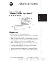
Relay Load Contact Wiring
dc
Return
+24V
dc
24V
dc
48V
dc
120V
ac
240V
ac
125V
dc
24V
dc
120V
ac
240V
ac
Representative Examples of Various Relay Loads

FLEX I/O 8 Relay Output Module 3
Publication 1794-IN019E-EN-P - May 2009
4. If daisychaining power to the next terminal base, connect a jumper
from terminal 51 (+V DC) on this base unit to terminal 34 on the
next base unit.
5. If continuing DC common to the next base unit, connect a jumper
from terminal 33 (common) on this base unit to terminal 16 on the
next base unit.
Wiring to a 1794-TBN or -TBNF Terminal Base Unit
1. Connect individual output relay contact (customer load) to even
numbered terminals (0 thru 14) on row (B) and odd numbered
terminals (1 thru 15) on row (C) as indicated in the table below.
The even numbered terminals are one pole of the relay contacts;
the odd numbered terminals are the other pole of the relay
contacts.
2. Connect 24V DC return to terminal 16 on the 16-33 row (B).
3. Connect +24V DC power to terminal 34 on the 34-51
row (C).
4. If daisychaining power to the next terminal base, connect a jumper
from terminal 51 (+V DC) on this base unit to terminal 34 on the
next base unit.
5. If continuing DC common to the next base unit, connect a jumper
from terminal 33 (common) on this base unit to terminal 16 on the
next base unit.
Wiring Connections for the 1794-OW8, 1794-OW8K, 1794-OW8XT
Image Table Memory Map
Installing or Changing a Fuse in the 1794-TBNF
This terminal base unit has fuse holders for 5X20mm fuses on each of the 8
even-numbered I/O terminals (0 thru 14 - row B). To install or change a
fuse:
1. Press the fuse holder down toward the terminal strip.
2. If replacing a fuse, remove the fuse from the fuse holder.
3. Insert a known good 5X20mm fuse (Littelfuse pt. no. 239003, 3.0A,
250V AC slow-blow) into the fuse holder.
4. Replace the fuse holder by rotating the fuse holder back to vertical
until it snaps into the locked position.
ATTENTION
Apply only 24V DC power to the power terminals on the terminal base unit.
Make certain that all relay wiring is properly connected before applying any
power to the module.
ATTENTION
When using 240V power to a relay, you must connect a snubber across the load.
Failure to connect a snubber across the load (relay contacts) can result in
generation of electromagnetic noise which could disrupt nearby electrical
equipment, including your 1794 FLEX I/O chassis. Use Allen-Bradley part number
599-KA04 or 1401-NX1.
ATTENTION
Apply only 24V DC power to the power terminals on the terminal base unit.
Make certain that all relay wiring is properly connected before applying any
power to the module.
17 18 19 20 21 22 23 24 25 26 27 28 29 30 31 32 33
0 1 2 3 4 5 6 7 8 9 10 11 12 13 14 15
16
51
34
1794-TB2
0 –15
34–51
16–33
A
B
C
Output Relay Contacts (customer loads)
17 18 19 20 21 22 23 24 25 26 27 28 29 30 31 32 33
0 1 2 3 4 5 6 7 8 9 10 11 12 13 14 15
16
35 36 37 38 39 40 41 42 43 44 45 46 47 48 49 50 51
34
1794-TB3
0 –15
34–51
16–33
A
B
C
Output Relay Contacts (customer loads)
0 1 2 3 4 5 6 7 8 9 10 11 12 13 14 15
18 19 20 21 22 23 3324 25 26 27 28 29 30 31 3217
35 36 37 38 47 48 49 5034
51
16
Label placed at top of wiring area.
Row A
Row B
Row C
Row A
Row B
Row C
39 40 41 42 43 44 45 46
1794-TB3S
Output
Channel
1794-TB2, -TB3, -TB3S 1794-TBN, -TBNF
Output Terminal Output Terminal
0 A-0 B-0
A-1 C-1
1 A-2 B-2
A-3 C-3
2 A-4 B-4
A-5 C-5
3 A-6 B-6
A-7 C-7
4 A-8 B-8
A-9 C-9
5 A-10 B-10
A-11 C-11
6 A-12 B-12
A-13 C-13
7 A-14 B-14
A-15 C-15
A-(even) = one contact of the relay
A-(odd) = the other contact of the relay
B-(even) = one contact of the relay
C-(odd) = the other contact of the relay
+24VDC C-34 thru C-51 (-TB3, -TB3S) C-34 and
C-51 (-TB2)
C-34 and C- 51
-24V DC (RET) B- 16 thru B-33 B-16 and B-33
Dec.
15 14 13 12 11 10 09 08 07 06 05 04 03 02 01 00
Oct.
17 16 15 14 13 12 11 10 07 06 05 04 03 02 01 00
Read
Word
Not used - reserved
Write
Word
Not used - set to 0 O7 O6 O5 O4 O3 O2 O1 O0
Where: O = Output number (O0 corresponds to output 0, O1 corresponds to output 1, and so on)
When bit = 0, output 0 is off, when bit 0 1, output 0 is on.
0246810121433
16
13 57 9 11131551
34
16, 0, 2, 4, 6,
8, 10, 12, 14, 33
34, 1, 3, 5, 7,
9, 11, 13, 15,
51
C
B
1794-TBN,
-TBNF
16 33
Even Numbered Terminals 0 thru 14
34 51
Odd Numbered T erminals 1 thru 15
Press down to open

Publication 1794-IN019E-EN-P - May 2009 4 PN-46788
Supersedes Publication 1794-IN019D-EN-P - June 2004 Copyright © 2009 Rockwell Automation, Inc. All rights reserved.
General
Attribute Value
Outputs per module 1 group of 8 Form A isolated (normally open)
electromechanical relays
Module location Mounts on 1794-TB2, -TB3, -TB3S, -TBN and -TBNF Terminal Base Units.
When using 1794-TBNF terminal base unit, use 3.0 A, 250V AC
slow-blow fuses (Littelfuse pt. no. 239003)
Off-State leakage
current (max at 240V AC)
1.0m A thru snubber circuit
Minimum contact load 100μA at 100mV DC
Output voltage range (load
dependent)
5-30V DC @ 2.0 A resistive
125V DC @ 0.22 A resistive
125V AC @ 2.0 A resistive
240V AC @ 2.0 A resistive
If used in European Zone 2 potentially explosive atmospheres:
1794-OW8 - voltages must be at or below 60V AC or 75V DC;
1794-OW8K - voltages must be at or below all voltage ratings.
Output current rating
(at rated power)
Resistive
2 A @ 5-30V DC
0.22 A @ 125V DC
2 A @ 125V AC
2 A @ 240V AC
Inductive
0.98 A steady state @ 5-30V DC, L/R = 7ms
0.5 A steady state @ 48V DC, L/R = 7ms
0.22 A steady state @ 125V DC, L/R = 7ms
2.0 A steady state, 15A make @ 120V AC,
PF = cos θ = 0.35
2.0 A steady state, 7.5A make @ 240V AC,
PF = cos θ = 0.35
Power rating
(steady state)
250W max. for 125V AC resistive output
480W max. for 240V AC resistive output
60W max. for 30V DC resistive output
27W max. for 125V DC resistive output
180VA max. for 125V AC inductive output
180VA max. for 240V AC inductive output
27VA max. for 30V DC inductive output
27VA max. for 125V DC inductive output
Output signal delay
OFF to ON
ON to OFF
10ms maximum (time from valid output on signal to relay energization by
module)
10ms maximum (time from valid output off signal to relay deenergization
by module)
Initial contact resistance 30mΩ
Switching frequency 1 operation/3s (0.3Hz at rated load) max
Bounce time 1.2ms (mean)
Expected life of
electrical contacts
Minimum 100,000 operations @ rated loads
Flexbus current 35 mA maximum
Power dissipation 5.5W
Thermal dissipation 18.8 BTU/hr maximum
Isolation voltage 250V (continuous), Basic Insulation Type, relay to relay, relay to
backplane, and relay to power
50V (continuous), Basic Insulation Type, power to backplane
Type tested at 1500V AC for 60 s, relay to relay, all combinations.
Type tested at 3250V DC for 60 s, relay to backplane and relay to power
Type tested at 900V DC for 60 s, power to backplane.
Fusing Fusing of outputs is recommended. Use 3.0 A, 250V AC slow-blow fuses
(Littelfuse pt. no. 239003).
Indicators 8 yellow status indicators - show status of individual outputs. If relay
output bit is on, corresponding output indicator is on.
Keyswitch position 9
Terminal screw torque Determined by installed terminal base
Dimensions (with module
installed)
94H x 94W x 69D mm (3.7H x 3.7W x 2.7D inches )
Enclosure None (open-style)
Wiring category
(1)
(1)
Use this Conductor Category information for planning conductor routing. Refer to Industrial Automation Wiring and
Grounding Guidelines, publication
1770-4.1.
2 - on signal ports
Wire size Determined by installed terminal base
Pilot Duty Rating C300, R150
North American temp code T4 (1794-OW8XT)
T5 (1794-OW8, 1794-OW8K)
IEC Temp Code T4 (1794-OW8XT)
T5 (1794-OW8, 1794-OW8K)
Environmental
Attribute Value
Operating temperature IEC 60068-2-1 (Test Ad, Operating Cold),
IEC 60068-2-2 (Test Bd, Operating Dry Heat),
IEC 60068-2-14 (Test Nb, Operating Thermal Shock):
0…55 °C (32…131 °F) (1794-OW8, 1794-OW8K)
-20…70 °C (-4…158 °F) (1794-OW8XT)
Non-operating
temperature
IEC 60068-2-1 (Test Ab, Unpackaged Non-operating Cold),
IEC 60068-2-2 (Test Bb, Unpackaged Non-operating Dry Heat),
IEC 60068-2-14 (Test Na, Unpackaged Non-operating Thermal Shock):
-40…85 °C (-40…185 °F)
Relative humidity IEC 60068-2-30 (Test Db, Unpackaged Damp Heat):
5…95% noncondensing
Vibration IEC 60068-2-6 (Test Fc, Operating):
5 g @ 10…500 Hz
Operating shock IEC 60068-2-27 (Test Ea, Unpackaged Shock):
12 g
Non-operating shock IEC 60068-2-27 (Test Ea, Unpackaged Shock):
50 g
Emissions CISPR 11:
Group 1, Class A
ESD immunity IEC 61000-4-2:
6 kV contact discharges
8 kV air discharges
Radiated RF immunity IEC 61000-4-3:
10V/m with 1 kHz sine-wave 80% AM from 80…2000 MHz
10V/m with 200 Hz 50% Pulse 100% AM at 900 MHz
10V/m with 200 Hz 50% Pulse 100% AM at 1890 MHz
3V/m with 1 kHz sine-wave 80% AM from 2000…2700 MHz
EFT/B immunity IEC 61000-4-4:
±2 kV at 5 kHz on signal ports
Surge transient
immunity
IEC 61000-4-5:
±1 kV line-line(DM) and ±2 kV line-earth(CM) on signal ports
Conducted RF immunity IEC 61000-4-6:
10V rms with 1 kHz sine-wave 80% AM from 150 kHz…80 MHz
Certifications (when product is marked)
(1)
(1)
See the Product Certification link at http://www.ab.com for Declaration of Conformity, Certificates, and other
certification details.
Attribute Value
c-UL-us UL Listed Industrial Control Equipment, certified for US and Canada. See UL File
E65584.
UL Listed for Class I, Division 2 Group A,B,C,D Hazardous Locations, certified for U.S.
and Canada. See UL File E194810.
CSA (1794-OW8, 1794-OW8K)
CSA Certified Process Control Equipment. See CSA File LR54689C.
CSA Certified Process Control Equipment for Class I, Division 2 Group A,B,C,D
Hazardous Locations. See CSA File LR69960C.
CE European Union 2004/108/EC EMC Directive, compliant with:
EN 61326-1; Meas./Control/Lab., Industrial Requirements
EN 61000-6-2; Industrial Immunity
EN 61000-6-4; Industrial Emissions
EN 61131-2; Programmable Controllers (Clause 8, Zone A & B)
European Union 2006/95/EC LVD, compliant with:
EN 61131-2; Programmable Controllers (Clause 11)
C-Tick Australian Radiocommunications Act, compliant with:
AS/NZS CISPR 11; Industrial Emissions
Ex (1794-OW8XT)
European Union 94/9/EC ATEX Directive, compliant with:
EN 60079-15; Potentially Explosive Atmospheres, Protection "n"
EN 60079-0; General Requirements
II 3 G Ex nA nC IIC T4X
when used at or below 60V AC or 75V DC
(1794-OW8, 1794-OW8K)
European Union 94/9/EC ATEX Directive, compliant with:
EN 60079-15; Potentially Explosive Atmospheres, Protection "n"
EN 60079-0; General Requirements
II 3 G Ex nA nC IIC T5X
when used at or below 60V AC or 75V DC
TÜV (1794-OW8, 1794-OW8K)
TÜV Certified for Functional Safety:
up to and including SIL 2
1/4