SUNNY Health Fitness SF-RB4616 Manuel utilisateur
- Catégorie
- Fitness, gymnastique
- Taper
- Manuel utilisateur

EASY ADJUSTABLE SEAT
RECUMBENT BIKE
SF-RB4616
USER MANUAL
English, Page 10 ~ 17 IMPORTANT! Please retain owner’s manual for maintenance and adjustment instructions. Your
satisfaction is very important to us, PLEASE DO NOT RETURN UNTIL YOU HAVE CONTACTED US:
[email protected] or 1- 877 - 90SUNNY (877-907-8669).
Español, Page 18 ~ 25 ¡IMPORTANTE! Conserve el manual del propietario para las instrucciones de mantenimiento y ajuste.
Su satisfacción es muy importante para nosotros, NO DEVUELVA HASTA HABERNOS ONTACTADO:
[email protected] ó 1- 877 - 90SUNNY (877-907-8669).
Français, Page 26 ~ 33 IMPORTANT! Veuillez conserver le manuel du propriétaire pour les instructions de réglage et d’entretien.
Votre satisfaction est très importante pour nous, VEUILLEZ NE PAS EFFECTUER DE RETOUR AVANT
DE NOUS AVOIR CONTACTÉ: support@sunnyhealthfitness.com ou 1- 877 – 90SUNNY (877-907-
8669).
Deutsche, Seite 34 ~ 41 WICHTIG! Bitte bewahren Sie das Benutzerhandbuch für Wartungs- und Einstellanweisungen auf. Ihre
Zufriedenheit ist besonders wichtig für uns, BITTE SCHICKEN SIE DAS PRODUKT NICHT ZURÜCK,
BEVOR SIE SICH MIT UNS IN VERBINDUNG GESETZT HABEN:
[email protected] oder 1-877-90SUNNY (877-907-8669).

1
IMPORTANT SAFETY INFORMATION
We thank you for choosing our product. To ensure your safety and health, please use this equipment correctly. It is important to
read this entire manual before assembling and using the equipment. Safe and effective use can only be achieved if the equipment
is assembled, maintained, and used properly. It is your responsibility to ensure that all users of the equipment are informed of all
warnings and precautions.
1. Before starting any exercise program, you should consult your physician to determine if you have any medical or physical
conditions that could put your health and safety at risk or prevent you from using the equipment properly. Your physician’s
advice is essential if you are taking medication that affects your heart rate, blood pressure, or cholesterol level.
2. Be aware of your body’s signals. Incorrect or excessive exercise can damage your health. Stop exercising if you experience
any of the following symptoms: pain, tightness in your chest, irregular heartbeat, shortness of breath, lightheadedness,
dizziness, or feelings of nausea. If you do experience any of these conditions, you should consult your physician before
continuing with your exercise program.
3. Keep children and pets away from the equipment. The equipment is designed for adult use only.
4. Use the equipment on a solid, flat level surface with a protective cover for your floor or carpet. To ensure safety, the equipment
should have at least 2 feet (60 CM) of free space all around it.
5. Ensure that all nuts and bolts are securely tightened before using the equipment. The safety of the equipment can only be
maintained if it is regularly examined for damage and/or wear and tear.
6. Always use the equipment as indicated. If you find any defective components while assembling or checking the equipment, or
if you hear any unusual noises coming from the equipment during exercise, discontinue use of the equipment immediately and
do not use until the problem has been rectified.
7. Wear suitable clothing while using the equipment. Avoid wearing loose clothing that may become entangled in the equipment.
8. Do not place fingers or objects into the moving parts of the equipment.
9. The maximum weight capacity of this unit is 300 pounds (135 KG).
10. The equipment is not suitable for therapeutic use.
11. To avoid bodily injury and/or damage to the product or property, proper lifting and moving are required.
12. Your product is intended for use in cool and dry conditions. You should avoid storage in extreme cold, hot or damp areas as
this may lead to corrosion and other related problems.
13. This equipment is designed for indoor and home use only, it is not intended for commercial use.
INFORMACIÓN IMPORTANTE DE SEGURIDAD
Gracias por haber elegido nuestro producto. Para garantizar su seguridad y salud, utilice este equipo correctamente. Es importante
que lea todo el manual antes de instalar y usar el equipo. Solo se puede garantizar el uso seguro y eficaz del equipo si se instala,
mantiene y utiliza correctamente. Es su responsabilidad asegurarse de que todos los usuarios de los equipos conozcan todas las
advertencias y precauciones.
1. Antes de comenzar algún programa de ejercicios, deberá consultar con su médico para determinar si tiene alguna condición
médica o física que pudiera poner en riesgo su salud y seguridad o que pudiera impedir que utilice correctamente el equipo.
Es importante que reciba las recomendaciones de su médico en caso de que esté tomando algún medicamento que pudiera
afectar su ritmo cardíaco, presión arterial o nivel de colesterol.
2. Esté atento a las señales que le envía su cuerpo. Ejercitarse de manera incorrecta o excesiva puede dañar su salud. Deje de
hacer ejercicio si experimenta alguno de los siguientes síntomas: dolor, opresión en el pecho, latidos cardíacos irregulares,
falta de aire, sensación de desmayo, mareos o sensación de náuseas. Si presenta alguna de esas condiciones, deberá
consultar con su médico antes de continuar con su programa de ejercicios.
3. Mantenga el equipo lejos del alcance de niños y mascotas. El equipo está diseñado para el uso exclusivo de adultos.
4. Utilice el equipo en una superficie plana y sólida con una cubierta protectora para su piso o alfombra. Para garantizar su
seguridad, el equipo debe tener por lo menos 2 pies (60 cm) de espacio libre a su alrededor.
5. Asegúrese de que todas las tuercas y pernos estén bien ajustados antes de usar el equipo. Solo puede conservarse la
seguridad del equipo si se inspecciona regularmente para detectar daños o desgaste.
6. Siempre utilice el equipo como se indica. Si encuentra algún componente defectuoso mientras instala o revisa el equipo, o si
escucha ruidos extraños que provienen de este mientras se ejercita, deje de utilizarlo inmediatamente y no lo utilice hasta que
el problema se haya corregido.
7. Use ropa adecuada cuando utilice el equipo. Evite usar ropa suelta que pueda enredarse en el equipo.
8. No coloque los dedos u objetos en las piezas móviles del equipo.
9. La capacidad de peso máximo de esta unidad es de 300 libras (135 kg).
10. Este equipo no es adecuado para uso terapéutico.
11. Muévase con cuidado cuando levante y mueva el equipo. Siempre utilice la técnica de levantamiento adecuada y pida ayuda
en caso de que sea necesario.
12. Su producto está diseñado para usarse en un lugar fresco y seco. Debe evitar tenerlo en lugares extremadamente fríos,
calientes o húmedos, ya que podría provocar corrosión y otros problemas afines.
13. Este equipo está diseñado solo para uso interior! No es para uso commercial!

2
INFORMATIONS DE SÉCURITÉ IMPORTANTES
Nous vous remercions d’avoir choisi notre produit. Pour votre santé et votre sécurité, veuillez utiliser correctement cet appareil. Il
est important de lire entièrement le présent manuel avant d’assembler l’appareil et de l’utiliser. L’utilisation sûre et efficace n’est
possible que si l’appareil est correctement assemblé, entretenu et utilisé. Il vous incombe de vous assurer que tous les utilisateurs
de l’appareil soient informés de tous les avertissements et précautions.
1. Avant d’entamer un programme d’exercices, consultez votre médecin pour déterminer si vous avez une quelconque disposition
physique ou médicale susceptible de mettre en danger votre santé et votre sécurité ou de vous empêcher d’utiliser cet appareil
correctement. L’avis de votre médecin est essentiel si vous prenez un médicament pouvant affecter le rythme cardiaque, la
pression ou le niveau de cholestérol.
2. Soyez à l’écoute des signaux de votre corps. Accompli de façon incorrecte ou excessive, l’exercice peut nuire à la santé.
Cessez de faire de l’exercice si vous ressentez l’un des symptômes suivants: douleur, serrement de la poitrine, rythme
cardiaque irrégulier, souffle court, étourdissement, vertige, ou sensations de nausée. Si vous éprouvez l’un de ces états,
consultez votre médecin avant de poursuivre votre programme d’exercice.
3. Gardez les enfants et les animaux de compagnie à distance de l’appareil. L’appareil est conçu pour l’utilisation exclusive par
des adultes.
4. Utilisez l’appareil sur une surface dure, plane et de niveau, avec une protection pour votre parquet ou tapis. Pour un usage sûr,
l’appareil doit disposer d’au moins 60 cm (2 pi) d’espace libre tout autour de lui.
5. Assurez-vous que tous les boulons et écrous soient bien serrés avant d’utiliser l’appareil. La sécurité de l’appareil ne peut être
entretenue qu’à condition de régulièrement vérifier l’absence de dommages ou d’usure.
6. Utilisez toujours l’appareil comme indiqué. Si vous trouvez un composant défectueux lors de l’assemblage ou de la vérification
de l’appareil, ou si vous entendez un bruit inhabituel en provenir pendant l’utilisation, cessez immédiatement l’exercice et
n’employez plus l’appareil tant que le problème n’a pas été résolu.
7. Portez des vêtements adéquats lors de l’utilisation de l’appareil. Évitez les vêtements amples qui risqueraient de se prendre
dans l’appareil.
8. Ne mettez pas le doigt ni aucun objet dans les pièces mobiles de l’appareil.
9. La capacité de poids maximale de cet appareil est de 135 kg (300 lb).
10. Cet appareil n’est pas adapté à un usage thérapeutique.
11. Soulevez et déplacez l’appareil avec précaution. Utilisez toujours les techniques adéquates de levage et demandez de l’aide
si nécessaire.
12. Votre produit est conçu pour usage dans un endroit sec et frais. Éviter de l’entreposer dans un endroit extrêmement froid,
chaud ou humide, car cela peut entraîner de la corrosion et des problèmes du même ordre.
13. Cet appareil est conçu pour un usage intérieur uniquement! Il n’est pas fait pour une utilisation commerciale!
WICHTIGE SICHERHEITSHINWEISE
Wir danken Ihnen, dass Sie sich für unser Produkt entschieden haben. Zur Gewährleistung Ihrer Sicherheit und Gesundheit
verwenden Sie dieses Gerät bitte ordnungsgemäß. Es ist wichtig, diese gesamte Bedienungsanleitung zu lesen, bevor Sie das
Gerät montieren und in Betrieb nehmen. Eine sichere und effektive Nutzung kann nur erreicht werden, wenn das Gerät
ordnungsgemäß montiert, gewartet und verwendet wird. Sie sind dafür verantwortlich, dass alle Benutzer des Geräts über alle
Warnungen und Vorsichtsmaßnahmen informiert werden.
1. Vor Beginn eines jeden Trainingsprogramms ist es ratsam, einen Arzt zu konsultieren, um festzustellen, ob Sie medizinische
oder körperliche Beschwerden haben, die Ihre Gesundheit und Sicherheit gefährden oder verhindern könnten, dass Sie das
Gerät ordnungsgemäß benutzen. Der Rat Ihres Arztes ist unerlässlich, wenn Sie Medikamente einnehmen, die Ihre
Herzfrequenz, Ihren Blutdruck oder Ihren Cholesterinspiegel beeinflussen.
2. Achten Sie auf die Signale Ihres Körpers. Falsches oder übermäßiges Training kann Ihre Gesundheit schädigen. Hören Sie
auf zu trainieren, wenn Sie eines der folgenden Symptome verspüren: Schmerzen, Engegefühl in Ihrer Brust, unregelmäßiger
Herzschlag, Kurzatmigkeit, Benommenheit, Schwindel oder Übelkeit. Wenn Sie einen dieser Zustände bemerken, sollten Sie
Ihren Arzt konsultieren, bevor Sie mit Ihrem Trainingsprogramm fortfahren.
3. Kinder und Haustiere dürfen nicht in der Nähe des Geräts sein. Das Gerät ist nur für den Gebrauch durch Erwachsene
bestimmt.
4. Verwenden Sie das Gerät auf einer festen, ebenen Fläche mit einer Schutzabdeckung für Ihren Boden oder Teppich. Um die
Sicherheit zu gewährleisten, sollte das Gerät ringsum mindestens 60 cm (2 ft) Freiraum haben.
5. Vergewissern Sie sich, dass alle Muttern und Bolzen fest angezogen sind, bevor Sie das Gerät benutzen. Die Sicherheit des
Gerätes kann nur gewährleistet werden, wenn es regelmäßig auf Beschädigungen und/oder Verschleiß überprüft wird.
6. Verwenden Sie das Gerät immer entsprechend den Angaben. Wenn Sie bei der Montage oder Überprüfung des Geräts
defekte Komponenten feststellen oder ungewöhnliche Geräusche vom Gerät während des Trainings hören, stellen Sie die
Verwendung des Geräts sofort ein. In diesem Fall sollten Sie es erst dann wieder in Betrieb nehmen, wenn das Problem
behoben ist.
7. Tragen Sie bei der Benutzung des Gerätes geeignete Kleidung. Vermeiden Sie das Tragen von loser Kleidung, die sich in
der Ausrüstung verfangen kann.
8. Stecken Sie keine Finger oder Gegenstände in die beweglichen Teile des Gerätes.
9. Die maximale Gewichtsbelastbarkeit dieser Einheit beträgt 135 kg (300 Pfund).
10. Dieses Gerät ist nicht für den therapeutischen Einsatz geeignet.
11. Um Personenschäden und/oder Schäden am Produkt oder Eigentum zu vermeiden, ist ein ordnungsgemäßes Hochheben
und Transportieren erforderlich.
12. Ihr Produkt ist für den Einsatz unter kühlen und trockenen Bedingungen bestimmt. Sie sollten die Lagerung in extrem kalten,
heißen oder feuchten Räumen vermeiden, da dies zu Korrosion und anderen damit verbundenen Problemen führen kann.
13. Dieses Gerät ist nur für den Innen- und Heimgebrauch bestimmt; es ist nicht für die gewerbliche Nutzung bestimmt!

3
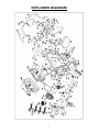
EXPLODED DIAGRAM

4
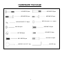
HARDWARE PACKAGE
#19 M8*60 2pcs
#20 M8*60 2pcs
#29 M8*50 2pcs
#26 Φ16*Φ8.5*1.5 6pcs
#25 M8*42 2pcs
#24 D8 4pcs
#23 Φ16*Φ8.5*1.5 12pcs
#27 M8 4pcs
#33 M6*15 2pcs
#21 M8*20 4pcs
#22 M8*45 4pcs
#90 S13-14-15-17 1pc
#91 S5 1pc
#28 M8*16 4pcs

5
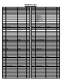
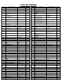
PARTS LIST
No.
Description
Spec.
Qty.
No.
Description
Spec.
Qty.
1
Main Frame
1
51
Eccentric Wheel
20*38
1
2
Front Post
1
52
Alloy Bushing
23*12.2*11
2
3
Front Stabilizer
1
53
Lock Washer
30*2
2
4
Cushion Frame
1
54
Idler Spacer
16*10.2*10
1
5
Handlebar
1
55
Pulley
240/J6, Hexagonal hole
1
6
Adjusting Tube
1
56
Foam Grip for
Handlebar 1
3*33*450
2
7
Magnetic Board
1
57
Foam Grip for
Handlebar 2
3*33*160
2
8
Idler Link
1
58
End Cap for Rear
Stabilizer
with 50
2
9
Rear Stabilizer
1
59
End Cap for Front
Stabilizer
with 50
2
10
Hex Tap Bolt
M6*70
1
60L/R
Pedal
2
11
Hex Nut
M6
2
61
Round End Cap
25*1.5 tube
4
12
Hex Tap Bolt
M6*70
1
62
Belt
370PJ6
1
13
Plastic Nut
M8
1
63
Seat Cushion
360*280*40
1
14
Hex Nut
M10*1*H5
2
64
Backrest Cushion
380*290*40
1
15
Taper Nut
M10*1*H4
2
65
Sleeve
Outer Recipe tube 80 *
40 * 1.5
2
16
Plastic Nut
M8, S13
4
66
Rectangular End Cap
60*30*1.5
2
17
Screw
ST4.2*20
8
67
Rectangular End Cap
38*38*1.5
2
18
Screw
ST4.2*20
5
68
Plug
Φ12
2
19
Carriage Bolt
M8*60
2
69L/R
Cover
2
20
Bolt
M8*60
2
70
Crank Plug
2
21
Bolt
M8*20
4
71
Arc Idler
1
22
Bolt
M8*45
4
72a
Tension Control Knob
1
23
Flat Washer
Φ16*Φ8.5*1.5
13
72b
Tension Control Wire
280mm
1
24
Spring Washer
D8
4
73
Tension Control Wire
55 max/760mm
1
25
Carriage Bolt
M8*42
2
74
Transportation Wheel
41*8.5*20
2
26
Arc Washer
Φ16*Φ8.5*1.5
6
75
Brake Block
40*38*32
1
27
Cap Nut
M8
4
76
EV Washer
40*20*3
1
28
Bolt
M8*16
4
77
Computer
100mm
1
29
Bolt
M8*50
2
77a
Computer Wire
1
30
Screw
M5*8
4
77b
Computer Wire
1
31
Screw
M8*38
2
77c
Computer Wire
1
32
Screw
M5*15
2
78
Trunk Wire
600mm
1
33
Screw
M6*15
2
79
Sensor
500mm, with seat
1
34
Lock Washer for Shaft
D12
1
80
Hand Pulse Sensor
700mm
2
35
Bolt
M5*45
1
81
Hand Pulse Wire 1
600mm
2
36
Arc Washer
20*6*1
1
82
Hand Pulse Wire 2
1600mm
1
37
Screw
M5*10
2
82a
Hand Pulse Wire 2
1
38
Bearing Housing
Φ56*15.5
2
82b
Hand Pulse Wire 2
1
39
Crank
40*220,1/2
1
83
Brake Handle
24*77*hole 12
1
40
Flywheel Spacer
16*10.2*17
1
84
Open Face Bearing
Φ46*8
2
41
Tension Spring
18*48, wire 2
1
85
Locking Nut
Φ46*12
1
42
Square Magnet
40*25*10
8
86
Locking Washer
Φ46*2
1
43
Round Magnet
15*6, without seat
1
87
Hex Nut
32*32*4
2
44
Inertia Axle
10*125*M10*1*17
1
88
Locking Nut
Φ46*12
1
45
Magnetic Flywheel
200*72.5/3kg
1
89
Washer
Φ40.5*3
1
46
Bearing
6000z
2
90
Spanner
S13-14-15-17
1
47
Tension Spring
18*48, Wire 2
1
91
Allen Wrench
S5
1
48
Tap Bolt
9.8*4*M8*15
1
92
Snap Ring
D3
1
49
Brake Handle
12*380
1
93
Location Grid
1
50
Eccentric Shaft
12*105
1
94
Screw
M3*10
9

6
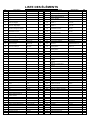
ISTA DE PIEZAS
n.°
Descripción
Especificaciones
Cant.
n.°
Descripción
Especificaciones
Cant.
1
Estructura Principal
1
51
Rueda Excéntrica
20*38
1
2
Barral Delantero
1
52
Buje de Aleación
23*12,2*11
2
3
Estabilizador Delantero
1
53
Arandela de Bloqueo
30*2
2
4
Estructura del Cojín
1
54
Espaciador de la Rueda de
Tensión
16*10,2*10
1
5
Manubrio
1
55
Polea
240/J6, orificio
hexagonal
1
6
Tubo de Ajuste
1
56
Empuñadura de Espuma
Para el Manubrio 1
3*33*450
2
7
Tablero Magnético
1
57
Empuñadura de Espuma
Para el Manubrio 2
3*33*160
2
8
Unión de la Rueda de
Tensión
1
58
Tapa del Extremo Para el
Estabilizador Trasero
con 50
2
9
Estabilizador Trasero
1
59
Tapa del Extremo Para el
Estabilizador Delantero
con 50
2
10
Perno de Cabeza
Hexagonal
M6*70
1
60 L/R
Pedal
2
11
Tuerca Hexagonal
M6
2
61
Tapa de Extremo Circular
Tubo de 25*1.5
4
12
Perno de Cabeza
Hexagonal
M6*70
1
62
Cinta
370PJ6
1
13
Tuerca de Plástico
M8
1
63
Cojín del Asiento
360*280*40
1
14
Tuerca Hexagonal
M10*1*H5
2
64
Cojín del Respaldo
380*290*40
1
15
Tuerca Cónica
M10*1*H4
2
65
Manguito
Tubo recipiente externo
80 * 40 * 1.5
2
16
Tuerca de Plástico
M8, S13
4
66
Tapa Rectangular del
Extremo
60*30*1.5
2
17
Tornillo
ST4,2*20
8
67
Tapa Rectangular del
Extremo
38*38*1.5
2
18
Tornillo
ST4,2*20
5
68
Conector
Φ12
2
19
Perno de Carrocería
M8*60
2
69L/R
Cubierta
2
20
Perno
M8*60
2
70
Tapón de la Manivela
2
21
Perno
M8*20
4
71
Rueda de Tensión en Arco
1
22
Perno
M8*45
4
72a
Perilla de Control de Tensión
1
23
Arandela Plana
Φ16*Φ8.5*1.5
13
72b
Cable de Control de Tensión
280mm
1
24
Arandela Elástica
D8
4
73
Cable de Control de Tensión
55 máx/760mm
1
25
Perno de Carrocería
M8*42
2
74
Rueda de Transporte
41*8,5*20
2
26
Arandela en Arco
Φ16*Φ8.5*1.5
6
75
Bloque de Freno
40*38*32
1
27
Tuerca de Sombrerete
M8
4
76
Arandela EV
40*20*3
1
28
Perno
M8*16
4
77
Computadora
100mm
1
29
Perno
M8*50
2
77a
Cable de la Computadora a
1
30
Tornillo
M5*8
4
77b
Cable de la Computadora b
1
31
Tornillo
M8*38
2
77c
Cable de la Computadora c
1
32
Tornillo
M5*15
2
78
Cable Troncal
600mm
1
33
Tornillo
M6*15
2
79
Sensor
500mm, con asiento
1
34
Arandela de Bloqueo Para
el Eje
D12
1
80
Sensor del Pulso de Mano
700mm
2
35
Perno
M5*45
1
81
Cable del Pulso de Mano 1
600mm
2
36
Arandela en Arco
20*6*1
1
82
Cable del Pulso de Mano 2
1600mm
1
37
Tornillo
M5*10
2
82a
Cable del Pulso de Mano 2
1
38
Caja de Rodamientos
Φ56*15.5
2
82b
Cable del Pulso de Mano 2
1
39
Manivela
40*220,1/2
1
83
Perilla del Freno
24*77*orificio 12
1
40
Espaciador de Volantes
16*10,2*17
1
84
Rodamiento de Boca Abierta
Φ46*8
2
41
Resorte de Tensión
18*48, cable 2
1
85
Tuerca de Bloqueo
Φ46*12
1
42
Imán Cuadrado
40*25*10
8
86
Arandela de Bloqueo
Φ46*2
1
43
Imán Redondo
15*6, sin asiento
1
87
Tuerca Hexagonal
32*32*4
2
44
Eje de Inercia
10*125*M10*1*17
1
88
Tuerca de Bloqueo
Φ46*12
1
45
Volante Magnético
200*72.5/3kg
1
89
Arandela
Φ40.5*3
1
46
Cojinete
6000z
2
90
Llave Inglesa
S13-14-15-17
1
47
Resorte de Tensión
18*48, cable 2
1
91
Llave Allen
S5
1
48
Perno
9.8*4*M8*15
1
92
Anillo Elástico
D3
1
49
Manija del Freno
12*380
1
93
Cuadrícula de Lubicación
1
50
Eje Excéntrico
12*105
1
94
Tornillo
M3*10
9

7
LISTE DES ÉLÉMENTS
Nº
Description
Spécification
Qté
Nº
Description
Spécification
Qté
1
Cadre Principal
1
51
Roue Excentrique
20*38
1
2
Montant Avant
1
52
Bague en Alliage
23*12,2*11
2
3
Stabilisateur Avant
1
53
Rondelle de Frein
30*2
2
4
Support de Coussin
1
54
Bague d’Espacement du
Pignon Tendeur
16*10,2*10
1
5
Guidon
1
55
Poulie
240/J6, trou hexagonal
1
6
Tube de Réglage
1
56
Poignée en Mousse Pour
Guidon 1
3*33*450
2
7
Panneau Magnétique
1
57
Poignée en Mousse Pour
Guidon 2
3*33*160
2
8
Jonction de Pignon Tendeur
1
58
Embout d’Extrémité du
Stabilisateur Arrière
avec 50
2
9
Stabilisateur Arrière
1
59
Embout d’Extrémité du
Stabilisateur Avant
avec 50
2
10
Boulon à Tête Hexagonale
M6*70
1
60L/R
Pédale
2
11
Écrou Hexagonal
M6
2
61
Embout d’Extrémité Arrondi
Tube 25*1,5
4
12
Boulon à Tête Hexagonale
M6*70
1
62
Courroie
370PJ6
1
13
Écrou en Plastique
M8
1
63
Coussin de Siège
360*280*40
1
14
Écrou Hexagonal
M10*1*H5
2
64
Coussinet du Dossier
380*290*40
1
15
Écrou Conique
M10*1*H4
2
65
Manchon
Tube receveur
extérieur 80*40*1,5
2
16
Écrou en Plastique
M8, S13
4
66
Embout d’Extrémité
Rectangulaire
60*30*1,5
2
17
Vis
ST4,2*20
8
67
Embout d’Extrémité
Rectangulaire
38*38*1,5
2
18
Vis
ST4,2*20
5
68
Bouchon
Φ12
2
19
Boulon de Carrosserie
M8*60
2
69L/R
Carter
2
20
Boulon
M8*60
2
70
Bouchon de Manivelle
2
21
Boulon
M8*20
4
71
Pignon Tendeur de l’Arc
1
22
Boulon
M8*45
4
72a
Bouton de Contrôle de
Tension
1
23
Rondelle Plate
Φ16*Φ8,5*1,5
13
72b
Câble de Contrôle de la
Tension
280mm
1
24
Rondelle à Ressort
D8
4
73
Câble de Contrôle de la
Tension
55 max/760mm
1
25
Boulon de Carrosserie
M8*42
2
74
Roulette de Transport
41*8,5*20
2
26
Rondelle Cambrée
Φ16*Φ8,5*1,5
6
75
Patin de Frein
40*38*32
1
27
Écrou Borgne
M8
4
76
Rondelle EV
40*20*3
1
28
Boulon
M8*16
4
77
Ordinateur
100mm
1
29
Boulon
M8*50
2
77a
Câble du Ordinateur a
1
30
Vis
M5*8
4
77b
Câble du Ordinateur b
1
31
Vis
M8*38
2
77c
Câble du Ordinateur c
1
32
Vis
M5*15
2
78
Câble de Jonction
600mm
1
33
Vis
M6*15
2
79
Capteur
500mm, avec siège
1
34
Rondelle de Blocage Pour
Arbre
D12
1
80
Capteur de Pouls
700mm
2
35
Boulon
M5*45
1
81
Câble du Capteur de Pouls 1
600mm
2
36
Rondelle Cambrée
20*6*1
1
82
Câble du Capteur de Pouls 2
1600mm
1
37
Vis
M5*10
2
82a
Câble du Capteur de Pouls 2
1
38
Boîtier de Roulement
Φ56*15,5
2
82b
Câble du Capteur de Pouls 2
1
39
Manivelle
40*220,1/2
1
83
Poignée de Frein
24*77, trou 12
1
40
Bague d’Espacement du
Volant d’Inertie
16*10,2*17
1
84
Roulement Face Ouverte
Φ46*8
2
41
Ressort de Tension
18*48, câble 2
1
85
Contre Écrou
Φ46*12
1
42
Aimant Carré
40*25*10
8
86
Rondelle de Sécurité
Φ46*2
1
43
Aimant Rond
15*6, sans siège
1
87
Écrou Hexagonal
32*32*4
2
44
Axe d’Inertie
10*125*M10*1*17
1
88
Contre Écrou
Φ46*12
1
45
Volant d’Inertie Magnétique
200*72,5/3 kg
1
89
Rondelle
Φ40,5*3
1
46
Roulement
6000 z
2
90
Clé Tricoise
S13-14-15-17
1
47
Ressort de Tension
18*48, câble 2
1
91
Clé Allen
S5
1
48
Boulon d’Assemblage
9,8*4*M8*15
1
92
Circlip
D3
1
49
Poignée de Frein
12*380
1
93
Grille d’Emplacement
1
50
Arbre Excentrique
12*105
1
94
Vis
M3*10
9

8
TEILELISTE
Nr.
Bezeichnung
Spezif.
Menge
Nr.
Bezeichnung
Spezif.
Menge
1
Hauptrahmen
1
51
Exzenterscheibe
20 x 38
1
2
Vorderpfosten
1
52
Metallbuchse
23 x 12,2 x 11
2
3
Stabilisator Vorne
1
53
Sicherungsscheibe
30 x 2
2
4
Polsterrahmen
1
54
Zwischenrad-Abstandhalter
16 x 10,2 x 10
1
5
Griffstange
1
55
Seilrolle
240/J6,
Sechskantloch
1
6
Verstellrohr
1
56
Schaumstoffgriff für
Griffstange 1
3 x 33 x 450
2
7
Platinenachse
1
57
Schaumstoffgriff für
Griffstange 2
3 x 33 x 160
2
8
Griffzwischenstück
1
58
Endkappe für Hinteren
Stabilisator
mit 50
2
9
Stabilisator Hinten
1
59
Endkappe für Vorderen
Stabilisator
mit 50
2
10
Sechskantgewindeschraube
M6 x 70
1
60L/R
Pedal
2
11
Sechskantmutter
M6
2
61
Runde Endkappe
25 x 1,5 Rohr
4
12
Sechskantgewindeschraube
M6 x 70
1
62
Riemen
370PJ6
1
13
Kunststoffmutter
M8
1
63
Sitzpolster
360 x 280 x 40
1
14
Sechskantmutter
M10 x 1 x H5
2
64
Rückenpolster
380 x 290 x 40
1
15
Konusmutter
M10 x 1 x H4
2
65
Hülse
Äußeres
Rezeptrohr 80 x
40 x 1,5
2
16
Kunststoffmutter
M8, S13
4
66
Rechteckige Endkappe
60 x 30 x 1,5
2
17
Schraube
ST4,2 x 20
8
67
Rechteckige Endkappe
38 x 38 x 1,5
2
18
Schraube
ST4,2 x 20
5
68
Stecker
Φ12
2
19
Schlossschraube
M8 x 60
2
69L/R
Abdeckung
2
20
Bolzen
M8 x 60
2
70
Kurbelstopfen
2
21
Bolzen
M8 x 20
4
71
Bogenspannrolle
1
22
Bolzen
M8 x 45
4
72a
Spannungssteuerungs Knopf
1
23
Unterlegscheibe
Φ16 x Φ8,5 x 1,5
13
72b
Spannungssteuerungs Draht
280mm
1
24
Federscheibe
D8
4
73
Spannungssteuerungs Draht
55 max/760mm
1
25
Schlossschraube
M8 x 42
2
74
Transportrad
41 x 8,5 x 20
2
26
Gewölbte Federscheibe
Φ16 x Φ8,5 x 1,5
6
75
Bremsklotz
40 x 38 x 32
1
27
Blindmutter
M8
4
76
EV-Beilagscheibe
40 x 20 x 3
1
28
Bolzen
M8 x 16
4
77
Computer
100mm
1
29
Bolzen
M8 x 50
2
77a
Computerkabel a
1
30
Schraube
M5 x 8
4
77b
Computerkabel b
1
31
Schraube
M8 x 38
2
77c
Computerkabel c
1
32
Schraube
M5 x 15
2
78
Stammkabel
600mm
1
33
Schraube
M6 x 15
2
79
Sensor
500mm, mit Sitz
1
34
Sicherungsscheibe für
Schaft
D12
1
80
Handpulssensor
700mm
2
35
Bolzen
M5 x 45
1
81
Handpulskabel 1
600mm
2
36
Gewölbte Federscheibe
20 x 6 x 1
1
82
Handpulskabel 2
1600mm
1
37
Schraube
M5 x 10
2
82a
Handpulskabel 2
1
38
Lagergehäuse
Φ56 x 15,5
2
82b
Handpulskabel 2
1
39
Kurbel
40 x 220 x 1/2
1
83
Bremshebel
24 x 77 x Löcher
12
1
40
Abstandhalter für
Schwungräder
16 x 10,2 x 17
1
84
Offenes Kugellager
Φ46 x 8
2
41
Spannfeder
18 x 48 x Draht 2
1
85
Kontermutter
Φ46 x 12
1
42
Vierkant-Magnet
40 x 25 x 10
8
86
Sicherungsscheibe
Φ46 x 2
1
43
Rundmagnet
15 x 6, ohne Sitz
1
87
Sechskantmutter
32 x 32 x 4
2
44
Trägheitsachse
10 x 125 x M10 x
1 x 17
1
88
Kontermutter
Φ46 x 12
1
45
Magnetisches Schwungrad
200 x 72,5/3 kg
1
89
Beilagscheibe
Φ40,5 x 3
1
46
Kugellager
6000z
2
90
Schraubenschlüssel
S13-14-15-17
1
47
Spannfeder
18 x 48, Draht 2
1
91
Inbusschlüssel
S5
1
48
Gewindeschraube
9,8 x 4 x M8 x 15
1
92
Sprengring
D3
1
49
Bremshebel
12 x 380
1
93
Positionsraster
1
50
Exzenterwelle
12 x 105
1
94
Schraube
M3 x 10
9

9
Ordering Replacement Parts (U.S. and Canadian Customers only)
Please provide the following information for us to accurately identify the part(s) needed:
✓ The model number (found on cover of manual)
✓ The product name (found on cover of manual)
✓ The part number found on the “EXPLODED DIAGRAM” and “PARTS LIST” (found near the
front of the manual)
Please contact us at [email protected] or 1- 877 - 90SUNNY (877-907-8669).
Pedido de piezas de repuesto (solo para clientes de EE. UU. y Canadá)
Proporcione la siguiente información para que podamos identificar con precisión las piezas
necesarias:
✓ El número de modelo (se encuentra en la portada del manual).
✓ El nombre del producto (se encuentra en la portada del manual).
✓ El número de pieza que se encuentra en el “ESQUEMA DE LAS PIEZAS” y en la “LISTA DE
PIEZAS” (se encuentra al principio del manual).
Contáctenos en [email protected] o 1- 877 - 90SUNNY (877-907-8669).
Pour commander des pièces de rechange (clients américains et canadiens seulement)
Veuillez fournir les informations suivantes afin que nous puissions identifier avec précision la pièce
ou les pièces requise(s):
✓ Le numéro de modèle (situé sur la couverture du manuel)
✓ Le nom du produit (situé sur la couverture du manuel)
✓ Le numéro de pièce figurant sur le « SCHÉMA ÉCLATÉ » et la « LISTE DES ÉLÉMENTS »
(situé vers le début du manuel)
Bestellung von Ersatzteilen (nur für US-amerikanische und kanadische Kunden)
Bitte geben Sie die folgenden Informationen an, damit wir das/die benötigte(n) Teil(e) genau
identifizieren können:
✓ Die Modellnummer (finden Sie auf dem Umschlag der Anleitung)
✓ Die Produktbezeichnung (finden Sie auf dem Umschlag der Anleitung)
✓ Die Teilenummer auf der „EXPLOSIONSDARSTELLUNG“ und der „TEILELISTE“ (finden Sie
vorne in der Anleitung)
Bitte kontaktieren Sie uns unter [email protected] oder 1- 877 - 90SUNNY (877-
907-8669).

10
ASSEMBLY INSTRUCTIONS
We value your experience using Sunny Health and Fitness products. For assistance with parts or
troubleshooting, please contact us at [email protected] or 1-877-90SUNNY (877-907-
8669).
Span
Ne
r to
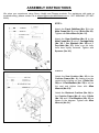
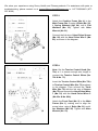
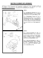
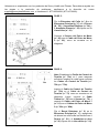
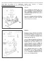
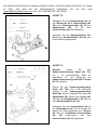
STEP 1:
Attach the Front Stabilizer (No. 3) to the
Main Frame (No. 1) using 2 Bolts (No. 20).
Tighten with Allen Wrench (No. 91).
Attach the Rear Stabilizer (No. 9) to the
Main Frame (No. 1) using 2 Carriage Bolts
(No. 19), 2 Arc Washers (No. 26) and 2
Cap Nuts (No. 27). Make sure the bolts
have been tightly fastened. Tighten with
Spanner (No. 90).
STEP 2:
Attach the Seat Cushion (No. 63) to the
Cushion Frame (No. 4), making sure the
correct side is facing up. Use 4 Bolts (No.
28) and 4 Flat Washers (No. 23) to secure
the seat and tighten them with Allen
Wrench (No. 91).
Attach the Backrest Cushion (No. 64) to
the Cushion Frame (No. 4) using 2 Bolts
(No. 29) and 2 Flat Washers (No. 23) as
shown in the diagram. Tighten with Allen
Wrench (No. 91).

11
We value your experience using Sunny Health and Fitness products. For assistance with parts or
troubleshooting, please contact us at [email protected] or 1-877-90SUNNY (877-907-
8669).
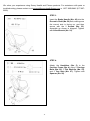
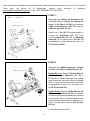
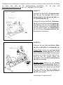
STEP 3:
Insert the Brake Handle (No. 49) into the
Eccentric Shaft (No. 50) hole, making sure
the correct side is facing up, and then
secure with the 2 Screws (No. 33).
Assemble as shown in diagram. Tighten
with Allen Wrench (No. 91).
STEP 4:
Attach the Handlebar (No. 5) to the
Cushion Frame (No. 4) using 2 Carriage
Bolts (No. 25), 2 Flat Washers (No. 23),
and 2 Cap Nuts (No. 27). Tighten with
Spanner (No. 90).

12
We value your experience using Sunny Health and Fitness products. For assistance with parts or
907-8669).
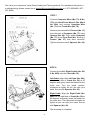
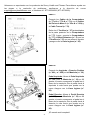
STEP 5:
Attach the Cushion Frame (No. 4) to the
Main Frame (No. 1) using 4 Bolts (No. 22),
4 Spring Washers (No. 24), and 4 Flat
Washers (No. 23). Tighten with Allen
Wrench (No. 91).
Connect the link wire of Hand Pulse Sensor
(No. 80) with the Hand Pulse Wire 2 (No.
82), as shown in the diagram.
STEP 6:
Note: Set the Tension Control Knob (No.
72a) at 1 to ensure enough wire length to
connect the Tension Control Wires (No.
72b & No. 73).
Insert the Tension Control Wire (No. 72b)
to Tension Control Wire (No. 73) as shown
in the diagram. Then connect the Trunk
Wire (No. 78) with the link wire of Sensor
(No. 79) and connect the Hand Pulse Wires
1 (No. 81) with the Hand Pulse Wires 2
(No. 82a & No. 82b).
Attach the Front Post (No. 2) to the Main
Frame (No. 1), making sure to align the
screw holes, using 4 Bolts (No. 21) and 4
Arc Washers (No. 26). Tighten with Allen
Wrench (No. 91).
72a

13
We value your experience using Sunny Health and Fitness products. For assistance with parts or
troubleshooting, please contact us at support@sunnyhealthfitness.com or 1-877-90SUNNY (877-
907-8669).
STEP 7:
Connect Computer Wires (No. 77a & No.
77b) with Hand Pulse Wires 2 (No. 82a &
No. 82b), and connect Computer Wire
(No. 77c) with Trunk Wire (No. 78).
Remove pre-assembled 2 Screws (No. 37)
from the back of Computer (No. 77) using
Spanner (No. 90). Then, attach Computer
(No. 77) to the Front Post (No. 2) using 2
Screws (No. 37) that were removed.
Tighten and secure with Spanner (No. 90).
STEP 8:
Connect the Left & Right Pedals (No. 60L
& No. 60R) onto the Crank (No. 39).
Left Pedal: Align the Left Pedal (No. 60L)
with the left side of Crank (No. 39) at 90
degrees and gently insert the pedal into the
crank arm. Turn the pedal counter-
clockwise as tightly as you can with your
hand. Secure with Spanner (No. 90).
Right Pedal: Align the Right Pedal (No.
60R) with the right side of Crank (No. 39) at
90 degrees and gently insert the pedal into
the crank arm. Turn the pedal clockwise as
tightly as you can with your hand. Secure
with Spanner (No. 90).
The assembly is complete!
39
39

14
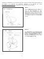
ADJUSTMENTS & USAGE GUIDE
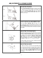
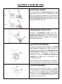
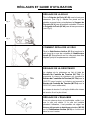
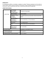
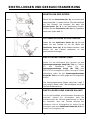
ADJUSTING BALANCE
In order to achieve a smooth and comfortable ride,
you must ensure that the recumbent bike is stable. If
you notice that the bike is unbalanced during use,
you should adjust the End Caps (No. 58) located
beneath the Rear Stabilizer (No. 9) by turning it
clockwise.
ADJUSTING THE SEAT
Pull the Brake Handle (No. 49) up to loosen (see Fig
1). Keep your feet on the pedals as leverage, then
move the Cushion Frame (No. 4) to the desired
position. Push the Brake Handle (No. 49) down to
tighten (see Fig 2).
Fig. 1
Fig. 2
HOW TO MOVE THE RECUMBENT BIKE
Hold the Rear Stabilizer (No. 9) and lift the
recumbent bike until the transportation wheels on the
Front Stabilizer (No. 3) touch the ground. Now you
can move the recumbent bike to the desired location
with ease.
ADJUSTING THE RESISTANCE
Adjust the resistance of the recumbent bike using the
Tension Control Knob (No. 72a). Increase the level
of resistance by turning the Tension Control Knob
(No. 72a) to the RIGHT (clockwise), decrease the
level of resistance by turning the Tension Control
Knob (No. 72a) to the LEFT (counter-clockwise).
Tension levels are set at Level 1 being the lowest
and Level 8 being the highest.
72a
58

15
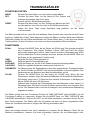
EXERCISE COMPUTER
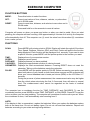
FUNCTION BUTTONS
MODE: Press this button to select functions.
SET: Press to set values of time, distance, calories, or pulse when
not in SCAN mode.
RESET: Press to reset time, distance, and calories to zero when not in
SCAN mode.
Press and hold for a few seconds to reset all values.
Computer will power on when you press any button or when you start to pedal. Once you start
pedaling, the computer will start counting. After approximately 4 minutes of no activity, the computer
will automatically shut off. This computer can (1) count the value from this workout (2) countdown
from a value you set.
SCAN: Press MODE until pointer points to SCAN. Display will rotate through all 6 functions:
Time, Speed, Distance, Calories, ODO, and Pulse. Pointer will point to the function
being displayed. Each function will be displayed for 4 seconds. If you want to view
a specific function, press MODE until the pointer points to the function you want.
TIME: Displays time of your exercise session.
SPEED: Displays current speed.
DISTANCE: Displays distance you have pedaled.
CALORIES: Displays the approximate number of calories burned.
ODOMETER: Displays the total accumulated distance. Pressing RESET does not reset the
odometer. Taking out the batteries resets the odometer.
PULSE: Press MODE until the pointer points to PULSE. Before measuring your pulse rate,
place both palms of your hands on both hand pulse sensors and the computer will
show your current heartbeat rate in beats per minute (BPM) on the LCD after 6~7
seconds.
During the process of pulse measurement, the measurement value may be higher
than the virtual pulse rate during the first 2~3 seconds, then will return to normal
level. The measurement value cannot be regarded as the basis of medical
treatment.
The computer has a countdown function for TIME, DISTANCE, and CALORIES. To use the
countdown function, press MODE to select TIME, DISTANCE, or CALORIES. Press SET to set the
value, and then you can start pedaling. The computer will countdown from the value you set. When
the countdown is done, it will automatically start counting from 0.
t NOTE:
If the display is faint or nonexistent, replace the batteries. When you replace the batteries replace
both at the same time. Do not mix battery types. Do not mix old and new batteries. Dispose old
batteries according to your state and regional guidelines.
FUNCTIONS

16
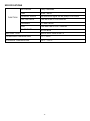
SPECIFICATIONS
FUNCTION
AUTO SCAN
Every 4 seconds
TIME
00:00 ~ 99:59
CURRENT SPEED
The maximum signal can be pickup is 99.9 MI/H
TRIP DISTANCE
0.00~99.99 MI or 0.00~9999 MI
CALORIES
0.1~999.9 KCAL
ODO
0.00~999.9 MI or 0.00 ~ 9999 MI
PULSE RATE
40~206 BPM
BATTERY TYPE
2pcs of SIZE –AAA or UM –4
OPERATING TEMPERATURE
0°C ~ +40°C
STORAGE TEMPERATURE
-10°C ~ +60°C

17
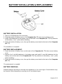
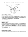
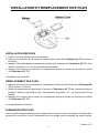
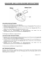
BATTERY INSTALLATION & REPLACEMENT
BATTERY INSTALLATION
1. Take out 2 AAA batteries from meter box.
2. Press the buckle of battery cover on the Computer (No. 77), then remove battery cover.
3. Install 2 AAA batteries into the battery case on the back of the Computer (No. 77). Pay attention
to the battery + and – poles before installing.
4. Press the buckle of battery cover, then put the battery cover back to the back of the Computer
(No. 77).
The installation is complete!
BATTERY REPLACEMENT
1. Press the buckle of battery cover on the back of the Computer (No. 77), then remove battery
cover.
2. Remove the 2 old AAA batteries in the battery case and install 2 new AAA batteries into the
battery case on the back of the Computer (No. 77). Pay attention to the battery + and – poles
before installing.
3. Press the buckle of battery cover, then put the battery cover back to the back of the Computer
(No. 77).
The replacement is complete!
BATTERY DISPOSAL
Dispose batteries according to the laws and regulations of your local region. Some batteries may
be recycled. When disposing or recycling, do not mix battery types.
Version 2.12

18
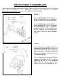
INSTRUCCIONES DE ARMADO
Valoramos su experiencia con los productos de Sunny Health and Fitness. Para obtener ayuda con
las piezas o la resolución de problemas, escríbanos a la dirección de correo
[email protected], o llámenos al 1-877-90SUNNY (877-907-8669).
Perio
Ne
r to
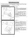
PASO 1:
Fije el Estabilizador Delantero (n.° 3) a la
Estructura Principal (n.° 1) con 2 Pernos
(n.° 20). Ajuste con la Llave Allen (n.° 91).
Fije el Estabilizador Trasero (n.° 9) a la
Estructura Principal (n.° 1) con 2 Pernos
de Carrocería (n.° 19), 2 Arandelas en
Arco (n.° 26) y 2 Tuercas de Sombrerete
(n.° 27). Asegúrese de ajustar firmemente
los pernos. Ajuste con la Llave Inglesa (n.°
90).
PASO 2:
Fije el Cojín del Asiento (n.° 63) a la
Estructura del Cojín (n.° 4), y asegúrese
de que el lado correcto esté hacia arriba.
Utilice 4 Pernos (n.° 28) y 4 Arandelas
Planas (n.° 23) para asegurar el asiento y
ajústelas con la Llave Allen (n.° 91).
Fije el Cojín del Respaldo (n.° 64) a la
Estructura del Cojín (n.° 4) con 2 Pernos
(n.° 29) y 2 Arandelas Planas (n.° 23)
como se muestra en el diagrama. Ajuste
con la Llave Allen (n.° 91).

19
Valoramos su experiencia con los productos de Sunny Health and Fitness. Para obtener ayuda con
las piezas o la resolución de problemas, escríbanos a la dirección de correo
[email protected], o llámenos al 1-877-90SUNNY (877-907-8669).
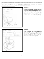
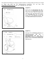
PASO 3:
Inserte la Manija del Freno (n.° 49) en el
orificio del Eje Excéntrico (n.° 50),
asegúrese de que el lado correcto esté
hacia arriba, y luego ajuste con los 2
Tornillos (n.° 33). Instale como se muestra
en el diagrama. Ajuste con la Llave Allen
(n.° 91).
PASO 4:
Fije el Manubrio (n.° 5) a la Estructura del
Cojín (n.° 4) con 2 Pernos de Carrocería
(n.° 25), 2 Arandelas Planas (n.° 23) y 2
Tuercas de Sombrerete (n.° 27). Ajuste
con la Llave Inglesa (n.° 90).
La page est en cours de chargement...
La page est en cours de chargement...
La page est en cours de chargement...
La page est en cours de chargement...
La page est en cours de chargement...
La page est en cours de chargement...
La page est en cours de chargement...
La page est en cours de chargement...
La page est en cours de chargement...
La page est en cours de chargement...
La page est en cours de chargement...
La page est en cours de chargement...
La page est en cours de chargement...
La page est en cours de chargement...
La page est en cours de chargement...
La page est en cours de chargement...
La page est en cours de chargement...
La page est en cours de chargement...
La page est en cours de chargement...
La page est en cours de chargement...
La page est en cours de chargement...
La page est en cours de chargement...
La page est en cours de chargement...
-
 1
1
-
 2
2
-
 3
3
-
 4
4
-
 5
5
-
 6
6
-
 7
7
-
 8
8
-
 9
9
-
 10
10
-
 11
11
-
 12
12
-
 13
13
-
 14
14
-
 15
15
-
 16
16
-
 17
17
-
 18
18
-
 19
19
-
 20
20
-
 21
21
-
 22
22
-
 23
23
-
 24
24
-
 25
25
-
 26
26
-
 27
27
-
 28
28
-
 29
29
-
 30
30
-
 31
31
-
 32
32
-
 33
33
-
 34
34
-
 35
35
-
 36
36
-
 37
37
-
 38
38
-
 39
39
-
 40
40
-
 41
41
-
 42
42
-
 43
43


SUNNY Health Fitness SF-RB4616 Manuel utilisateur
- Catégorie
- Fitness, gymnastique
- Taper
- Manuel utilisateur
dans d''autres langues
Documents connexes
-
 SUNNY Health Fitness SF-RB4905 MAGNETIC RECUMBENT EXERCISE BIKE Manuel utilisateur
-
 SUNNY Health Fitness P2100 Manuel utilisateur
-
SUNNY Health Fitness SF-B0891 Manuel utilisateur
-
SUNNY Health Fitness SF-A020052 Manuel utilisateur
-
 SUNNY Health Fitness SF-RW5856 Manuel utilisateur
-
 SUNNY Health Fitness SF-RB4708 Cross Training Magnetic Recumbent Bike Manuel utilisateur
-
 SUNNY Health Fitness SF-E3890 Manuel utilisateur
-
SUNNY Health Fitness SF-RW5515 Manuel utilisateur


Autres documents
-
 Sunny Health & Fitness SF-B1423 Manuel utilisateur
-
Sunny SF-XF9938 Manuel utilisateur
-
Sunny SF-T1407M Manuel utilisateur
-
-
-
Sunny SF-B1423 Manuel utilisateur
-
Sunny SF-RW5515 Manuel utilisateur
-
 Tool Fitness Techness SE 400 Le manuel du propriétaire
-
-
ProForm PFIVEL60214 Le manuel du propriétaire

