
Electric Tankless Water Heaters
IF YOU HAVE QUESTIONS OR COMMENTS, CONTACT US.
SI TIENE DUDAS O COMENTARIOS, CONTÁCTENOS.
POUR TOUTE QUESTION OU TOUT COMMENTAIRE, NOUS CONTACTER.
1-888-895-4549 WWW.CRAFTSMAN.COM
Models:
CMXTEPA0018 (18kW)
CMXTEPA0024 (24kW)
CMXTEPA0029 (29kW)
CMXTEPA0036 (36kW)
INSTRUCTION MANUAL

2
For California residents / Pour les résidents de la Californie / Para residentes en California
WARNING: Cancer and Reproductive Harm -
www.P65Warnings.ca.gov.
AVERTISSEMENT: Cancer et Troubles de l'appareil reproducteur -
www.P65Warnings.ca.gov.
ADVERTENCIA: Cáncer y Daño Reproductivo -
www.P65Warnings.ca.gov.
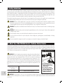
Important Safety Guideline
THIS INSTRUCTION MANUAL SHOULD BE SAVED FOR FUTURE REFERENCE.
Denitions: Safety Alert Symbols and Words
This instruction manual uses the following safety alert symbols and words to alert you to hazardous situations and your risk of personal
injury or property damage.
DANGER: Indicates an imminently hazardous situation which, if not avoided, will result in death or serious injury.
WARNING: Indicates a potentially hazardous situation which, if not avoided, could result in death or serious injury.
CAUTION: Indicates a potentially hazardous situation which, if not avoided, may result in minor or moderate injury.
(Used without word) Indicates a safety related message.
NOTICE: Indicates a practice not related to personal injury which, if not avoided, may result in property damage.
WARNING: PLEASE READ THIS INSTRUCTION MANUAL THOROUGHLY AND COMPLETELY BEFORE INSTALLATION & USE. FAILURE TO
DO SO COULD CAUSE DAMAGE TO PROPERTY, SERIOUS INJURY OR DEATH, AND VOID YOUR WARRANTY.
Please contact us directly, should you have any questions regarding your unit.
Phone: 1-888-895-4549

3
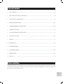
Table of Contents
1. SAFETY GUIDELINES --------------------------------------------------------------------------------------------------------04
2. ABOUT YOUR ELECTRIC TANKLESS WATER HEATER ----------------------------------------------------------------------------04
3. SELECTING AN INSTALLATION LOCATION -------------------------------------------------------------------------------------05
4. MOUNTING YOUR WATER HEATER --------------------------------------------------------------------------------------- 05-07
5. PLUMBING REQUIREMENTS AND PRECAUTIONS -------------------------------------------------------------------------- 07-08
6. PLUMBING INSTALLATION ---------------------------------------------------------------------------------------------------08
7. ELECTRICAL REQUIREMENTS AND PRECAUTIONS -----------------------------------------------------------------------------09
8. ELECTRICAL INSTALLATION ---------------------------------------------------------------------------------------------- 09-12
9. FLOW RATE ---------------------------------------------------------------------------------------------------------------- 13
10. OPERATION GUIDE ------------------------------------------------------------------------------------------------------ 13-14
11. CARE AND MAINTENANCE --------------------------------------------------------------------------------------------------14
12. USER INTERFACE/CONTROLS -------------------------------------------------------------------------------------------- 15-16
13. TROUBLESHOOTING ---------------------------------------------------------------------------------------------------- 17-18
14. RESET UNIT ----------------------------------------------------------------------------------------------------------------18
Before Installing
By installing this product, you acknowledge the terms of the manufacturer’s warranty and authorized dealer’s return policy. Once the heater
is installed, do not return the product to the place of purchase. If you have any questions regarding the warranty or the product return
policies, please contact us by phone or email.

4
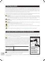
1. Safety Guidelines
Please read this manual thoroughly before installing & using the instant water heater. Failure to comply with the safety, installation or
operating instructions will void the product warranty. Manufacturer and distributor of the product will not be liable for any damage or
injury caused by the failure to comply with the installation and operating instructions specified in this manual or the improper use of the
product. Ensure that this product is installed in accordance with the national, state or local electrical and plumbing codes applicable to your
area, and as specified in our instructional guide to get the best performance from your Instant Water Heater.
This product has more than one power connection source. Do not attempt to install, clean, inspect, disassemble, service or repair the water
heater without shutting off all the power sources to the unit on the main electrical panel using the circuit breaker.
WARNING: Failure to adhere might result in severe injury or death. The water heater must be installed in compliance with all
national, state, provincial and local electrical and building regulations. We recommend that you consult a qualified electrician and
a qualified plumber if you have questions about anything relating to codes or regulations for this product.
WARNING: This product is intended for household and indoor use only. Do not immerse in water in order to avoid damage, injury
or death.
WARNING: The breaker used to power this unit must be grounded by means of the electrical panel. Failure to adhere might result
in damage, injury or death.
The heater must be directly connected to dedicated circuit breakers on the main electrical panel.
Do not install the heater where it may be subjected to direct sunlight, rain, splashing water, moisture/humidity or freezing
temperatures.
This unit is intended for heating water only. Do not attempt to use the unit for heating any other kind of liquid.
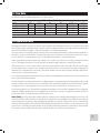
2. About Your CRAFTSMAN Electric Tankless Water Heater
Congratulations on making the decision to purchase one of the best and finest Instant Water Heaters currently available in the market today!
Your new Instant Water Heater features advanced water flow rate and temperature sensors which are designed to modulate power to the
heating elements to maintain a user-selected output water temperature range for 18kW / 24kW / 29kW / 36kW: 86°F (30°C) to 122°F
(50°C) (subject to the temperature of the incoming water).
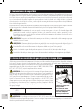
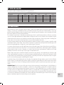
WARNING: When selecting the water temperature setting of your Instant Water Heater’s
thermostat, factors such as safety and energy conservation should be considered. Continuous
exposure of the skin to water temperatures above 120°F (49°C) can result in severe burns or
death. The maximum temperature to be set on this Instant Water Heater’s thermostat is 122°F
(50°C). Always take precaution to feel the water before bathing or showering to make sure the
temperatures are not too hot. You are required to read and comply with the Time/Temperature
Relationship Chart on the following page to determine the right water temperature for your
home.
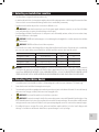
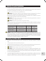
Time/Temperature
Relationship in Scalds
120°F (49°C)
Exposure for more than 5 minutes
122°F (50°C) Around 3 minutes of exposure
WARNING: You may require a 120°F (49°C) or lower thermostat setting to prevent contact with “HOT” water, if you have small
children, disabled, or elderly persons in your home. The temperature of the water is regulated by the electronic control on the front of the
water heater.
• Children, disabled and
elderly are at high risk of
being scalded.
• See instruction manual
before setting your desired
hot water temperature
• Always feel water before
bathing or showering

5
3. Selecting an Installation Location
• This Water Heater is designed for indoor installation only.
• It should not be installed in a location where it might be subjected to freezing temperatures as the freezing of the water in the Water
Heater can lead to severe and irreversible damages which are not covered under your warranty.
• The Water Heater should not be placed in a location that is difficult to access.
•
WARNING: Ensure that the water heater, as well as the power supplies and water connections, are out of reach of children
as the outlet water pipe can get very hot and touching can lead to injury.
• Avoid installing your tankless water heater in a location prone to excessive humidity, moisture, or dust, or in an area where it may
be splashed with water or other liquids.
WARNING: DO NOT install underwater pipes or air conditioning lines that might leak or condense moisture that could then
drip onto the heater.
WARNING: DO NOT install above electrical boxes or junctions.
• Do not install in areas which can be damaged due to leakage from the Water Heater. However, safety measure such as suitable drip
pan or an active water leak detector and shutoff valve should be installed in such areas that cannot be avoided.
Item # Unit dimensions (inches) Weight (lbs) Connections
CMXTEPA0018 (18kW) 15.52 x 4.49 x 13.9 9.21 1/2”
CMXTEPA0024 (24kW) 18.74 x 4.53 x 14.76 12.17 3/4”
CMXTEPA0029 (29kW) 18.74 x 4.53 x 14.76 12.17 3/4”
CMXTEPA0036 (36kW) 23.23 x 4.53 x 14.77 16.23 3/4”
WARNING: Water heaters are heat producing appliances. In order to avoid damage, injury or death, there shall be no materials
stored against the water heater and proper care shall be taken to prevent unnecessary contact (especially by children) with the
water heater. UNDER NO CIRCUMSTANCES SHALL FLAMMABLE MATERIALS, SUCH AS GASOLINE OR PAINT THINNER BE USED OR
STORED IN THE VICINITY OF THIS WATER HEATER OR ANY LOCATION FROM WHICH FUMES COULD REACH THE WATER HEATER.
4. Mounting Your Water Heater
1. Your tankless water heater should be secured to a solid mounting surface with four screws, (minimum 1” (25.4mm) long).
2. Ensure that the unit is level before fastening the screws in place.
3. The unit must be installed in an upright position with the water inlet and outlet at the bottom of the unit. Do not install inversely
with connections facing up or sideways with connections facing right or left.
4.
WARNING: Do not install the unit above electrical boxes or junctions.
5.
WARNING:The water heater must be installed in a manner that prevents contact with flammable liquids and gases. Keep
these flammable materials at least two feet away from the heater and the hot water outlet pipe. The water heater and the hot water
outlet pipe must be secured, and out of children’s reach to prevent tampering with controls or contact with an extremely hot pipe.
6. If installing the heater on an upper floor or attic, make sure installation complies with the local codes. Install a drip pan with
drainage, or a leak detector and automatic shutoff valve, to prevent damage in case of any leakage.

6
24kW, 29kW
18W
Fig. 3 Fig. 4
Fig. 5
Do not install upside down
or on its side
Fig. 6
Water Pre-
Filter
118
º
F
temp
Fig. 3 Fig. 4
Fig. 5
Do not install upside down
or on its side
Fig. 6
Water Pre-
Filter
118
º
F
temp
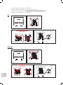
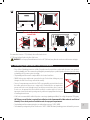
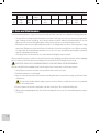
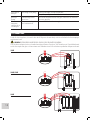
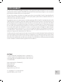
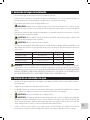
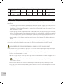
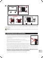
a. Remove the appliance cover. (Heater cover) (figure 3)
b. Mount the unit on the wall with 4 screws at the marked points (figure 4)
c. Make sure the unit is leveled horizontally, with water inlets and outlets at the bottom (fig.5)
D. Make sure the unit includes the water pre-filter (fig.6)

7
Recommended clearances: 12” (304.8mm) above and below the heater
6” (152.4mm) in front of and to the sides of the heater
WARNING: Please keep any flammable materials at least 24” (609.6mm) away from the water heater and hot water outlet pipe.
5. Plumbing Requirements and Precautions
• Please follow all plumbing instructions carefully. This product must be installed in accordance with all national, state, provincial,
and local plumbing codes. We recommend consulting with your municipality or a qualified plumber if you have questions relating
to plumbing codes for your area prior to installing.
• The plumbing installation must be completed before the electrical installation.
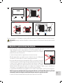
• DO NOT solder any pipe with the unit connected to the pipe. The heat from soldering may cause
damage to the flow sensor. Doing so will void the warranty.
• The use of a temperature pressure relief valve (T&P) is not required for most installations because
the tankless water heater does not use a storage tank. UL Standard 499 does not require that a
pressure relief valve is used, although it may be needed to meet installation codes in your area.
In such cases, the pressure relief valve should be installed in accordance with local codes. It is
important to ensure that the unit is operating correctly, and that air is purged from the valve prior
to installing the water heater.
• A T&P valve is recommended for added safety when connecting to plumbing rated Metal, Flex or High-Temperature CPVC piping.
NOTE: A pressure relief valve is required for installations in the Commonwealth of Massachusetts and State of
Kentucky. Please check your local installation codes for any special requirements.
• The plumbing installation requires piping that can withstand pressure up to 120PSI / 8 BAR.
• The maximum operating water pressure for this unit is 150PSI / 10BAR. Residential plumbing systems with unstable pressure or
36W
Fig. 3 Fig. 4
Fig. 5
Do not install upside down
or on its side
Fig. 6
Water Pre-
Filter
118
º
F
temp
Fig. 7
Do not solder any piping to the
unit’s Connection points

8
pressure above 5 BAR require the application of a pressure reduction valve set to 60-75PSI / 4-5 BAR for optimal performance.
• The water supply flow rate must be at least 0.5 Gallons per Minute (GPM) to ensure proper operation.
• Flexible water hoses are recommended to be used with your water heater when installing your water heater. When connecting
the inlet water pipe to the unit, use a wrench to hold the unit’s connection, and another wrench to tighten so that the flow sensor
on the unit will not be loosened or damaged. Do not over-tighten the water inlet and outlet connections to avoid severe internal
damage to the water heater.
• We recommend the installation of a manual shut-off valve (ball valve) on the inlet and outlet of the water heater to create a
convenient shut-off point if future maintenance or servicing is required. Before connecting the pipes to the water heater, it is highly
essential to flush the lines to eliminate all the plumbing paste or residue in the lines caused by any welding or soldering.
• All the water pipes within 3 feet (1 meter) of the inlet and outlet connections are recommended to be rated for high-temperature
applications with 150°F (66°C) minimum.
• Before proceeding to the electrical installation, run water through the unit for several minutes to flush out any air bubbles from the
water line.
6. Plumbing Installation
STEP 1: Thoroughly flush cold supply line of debris.
STEP 2: Connect the HOT WATER line to the water heater OUTLET. The water heater outlet can be seen on the left side of the heater when
facing the unit. Connect the COLD-WATER line to the water heater marked COLD WATER INLET which is located on the right side when
facing the unit.
* Pre-heated water can be connected to the cold water inlet, where this unit will act as a booster.
STEP 3: After tightening both fittings at the water heater, several hot water faucets should be opened to allow the flow of water through
the water heater for at least 2 to 3 minutes. This process purges all the air from the water lines and MUST be performed before turning on
the power at the unit.
FAILURE TO FOLLOW THIS STEP MIGHT CAUSE PERMANENT DAMAGE TO THE HEATING ELEMENTS. (The power to the heater should be
turned off and the air purged out of the lines before turning the power on anytime maintenance is performed on the water heater or the
homes plumbing system, as air might have been introduced into the plumbing pipes.)
STEP 4: Carefully inspect all connections, units, and the pressure relief device for leaks after the plumbing installation is completed. If there
are no leaks present, you can proceed to the electrical installation.
CAUTION: If you detect a water leak from the water heater at this point, turn off the water supply at the shut off valve on the unit’s
incoming water supply and contact us at 1-888-895-4549.
Plumbing Specications
Minimum water flow to activate the unit 0.5 gpm
Working pressure 0.5–10 BAR (7–150 psi)
Tested pressure (maximum) 20 BAR (290 psi)
Water connections 18kW 1/2” NPT
Water connections 24, 29, 36kW 3/4” NPT

9
7. Electrical Requirements and Precautions
Manufacturer recommends that this product be installed in accordance with all applicable national, state, provincial, and local electrical
codes. Consult a qualified and licensed electrician if you have questions or are unsure about anything relating to codes for this product. The
heater must be connected to a dedicated circuit breaker on the main electrical panel.
WARNING: As with all electrical appliances, it’s crucial to first shut off all power to the unit directly at the fuse or breaker box before
attempting to install, repair or disassemble this water heater. Ensure that the breaker is shut off. SERIOUS BODILY INJURY OR DEATH COULD
OCCUR IF YOU IGNORE THIS WARNING.
CAUTION: All wiring (wire gauge), as well as circuit protection (breaker), must comply with the U.S. National Electrical Code (NEC)
in the USA or the Canadian Electrical Code (CEC) in Canada. Failure to do so could lead to property damage, personal injury, and void your
warranty.
Note: The Canadian Electrical Code generally requires that all supply wires and corresponding circuit protection used for domestic hot water
heating and hydronic heating applications be sized to a minimum of 125% of the maximum current rating of the heater (check heater
specification details below).
Before installing this tankless water heater, ensure that sufficient electrical power is available in the home to handle the maximum
amperage load of the applicable heater.
IMPORTANT NOTES:
The heater requires set of wire and ground (see wiring diagram on page 10-11)
• Please see electrical specifications by heater input and wiring diagram on the page 10-11 for additional electrical information.
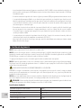
8. Electrical Installation
STEP 1: Take the wire pair and connect to the breaker (see wiring diagram). Be sure that the breaker is connected to one black wire and
one red wire. Be sure the power to the unit is shut off using the dedicated circuit breakers in the main electrical panel.
STEP 2: Run the correct set of power cable wires from the circuit breaker in the main electrical panel to the water heater by utilizing a
suitable wire gauge which meets all applicable electrical codes for the size of the breaker. Then, connect the power cable to the block
terminal within the water heater.
STEP 3: Unit requires a ground conductor for the incoming circuit.
STEP 4:
DOUBLE CHECK the electrical connections and ensure the wire connections are correct, tight and secure. It’s important to
confirm that the right breaker size and wire gauge has been used and that the unit has been connected to a ground in accordance with
applicable codes. Be sure to reattach the front cover of the unit with two screws.
STEP 5: Ensure that all the air has been purged from the water lines before turning on power to the unit. Refer to STEP 3 in the plumbing
installation section. Restore power to the unit through the dedicated circuit breaker in the main electrical panel.
It is crucial to follow the wire connection as shown and ensure all connections are made correctly for proper operation of the
unit. The unit will not operate correctly, even though it turns on and otherwise appears to function, if you mix up one set of wire
with another.

10
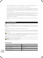
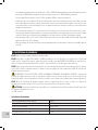
Electrical Specications by Heater Input
Item # kW Max Amps Required Breaker Req. Wire Size
18kW 18 75 2 x 40A Double Pole 2 x 8/2 AWG with Ground
24kW 24 100 3 x 40A Double Pole 3 x 8/2 AWG with Ground
29kW 28.8 120 3 x 40A Double Pole 3 x 8/2 AWG with Ground
Power Rates
Item # 240V 220V 208V
18kW 18,000 Watts 15,125 Watts 13,520 Watts
24kW 24,000 Watts 20,166 Watts 18,026 Watts
29kW 28,800 Watts 24,200 Watts 21,632 Watts
Your tankless water heater is now installed and ready to use! Follow the General Operating Instructions to complete the setup.
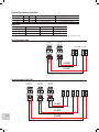
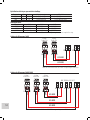
Terminal Block in Unit
40 Amp
Double Pole
40 Amp
Double Pole
40 Amp
Double Pole
40 Amp
Double Pole
40 Amp
Double Pole
Unit Requires 10 AWG ground wire - one for each 240V circuit
Unit Requires 10 AWG ground wire - one for each 240V circuit
L1L1 L2
8/2 AWG
8/2 AWG
L2
240V
240V
L1 L2 L1 L2
L1L1L1 L2
8/2 AWG
8/2 AWG
8/2 AWG
L2L2
240V
240V
240V
L1 L2 L1 L2 L1 L2
Wiring Diagram for 18kW
Wiring Diagram for 24kW, 29kW

11
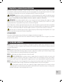
Electrical Specications by Heater Input
Item # kW Max Amps Required Breaker Req. Wire Size
36kW 36 150 4 x 40A Double Pole 4 x 8/2 AWG with Ground
Power Rates
Item # 240V 220V 208V
36kW 36,000 Watts 30,250 Watts 27,040 Watts
Your tankless water heater is now installed and ready to use! Follow the General Operating Instructions to complete the setup.
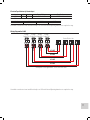
40 Amp
Double Pole
40 Amp
Double Pole
40 Amp
Double Pole
40 Amp
Double Pole
Unit Requires 10 AWG ground wire - one for each 240V circuit
L1L1L1 L2
8/2 AWG
8/2 AWG
8/2 AWG
L2L2
240V
240V
240V
L1 L2 L1 L2 L1 L2
L1 L2
240V
L1 L2
8/2 AWG
Your tankless water heater is now installed and ready to use! Follow the General Operating Instructions to complete the setup.
Terminal Block in Unit
Wiring Diagram for 36kW

12
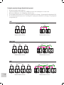
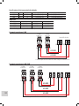
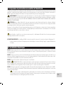
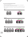
Testing the connections from your Breaker Panel to your unit
1. Measure the voltage by using AC multimeter.
2. Verify All circuit breakers are in the ON position. DO NOT turn on water while conducting this test or turn on unit.
3. Make sure your Multimeter is set to testing Voltage and in AC position.
4. Place the multimeter probes between each L1-L2 pairing on the terminal block (see drawing) – Each pairing should read approximately 240V.
5. Place the multimeter probes between each L1-L1 pairing and L2-L2 pairing on the terminal block (see drawing) - Each pairing should
read approximately 0V.
TERMINAL BLOCK IN THE UNIT
TERMINAL BLOCK IN THE UNIT
TERMINAL BLOCK IN THE UNIT
Measurement 1- Vac
Measurement 1- Vac
Measurement 1- Vac
L1 L2
240V
240V
L1 L2
240V
240V
L1 L2
240V
240V
L1 L2
240V
240V
L1 L2
240V
240V
L1 L2
240V
240V
L1 L2
240V
240V
L1 L2
240V
240V
L1 L2
240V
240V
TERMINAL BLOCK IN THE UNIT
TERMINAL BLOCK IN THE UNIT
TERMINAL BLOCK IN THE UNIT
Measurement 2- Vac
Measurement 2- Vac
Measurement 2- Vac
L1 L2
0V
240V
L1 L2
0V
240V
L1 L2
0V 0V
240V
L1 L2
0V 0V
240V
L1 L2
240V
L1 L2
0V 0V 0V
240V
L1 L2
0V 0V 0V
240V
L1 L2
240V
L1 L2
240V
18kW
24kW/ 29kW
36kW

13
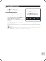
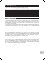
9. Flow Rate
The chart below indicates maximum temperature rise for a given flow rate
TEMPERATURE RISE CHART (GPM)
Item # kW 30°F 40°F 50°F 60°F 70°F
CMXTEPA0018 (18kW) 18 1.75 GPM 2.04 GPM 2.46 GPM 3.06 GPM 4.1 GPM
CMXTEPA0024 (24kW) 24 5.2 GPM 3.95 GPM 3.52 GPM 3.3 GPM 2.4 GPM
CMXTEPA0029 (29kW) 28.8 5.9 GPM 4.5 GPM 3.87 GPM 3.47 GPM 2.8 GPM
CMXTEPA0036 (36kW) 36 6.2 GPM 5.15 GPM 4.4 GPM 3.9 GPM 3.1 GPM
Based on 105°F Output Water Temp / GPM = Gallons Per Minute
10. Operation Guide
Operating your new tankless water heater is similar to using any traditional water heating system. However, it is essential that you carefully
read all setup procedures, operating instructions and tips to ensure the maximum performance and energy savings from your new water
heater. We recommend that all members of the household read these General Operating Instructions.
This electric water heater is designed to supply hot water. The unit contains heating elements within, capable of heating water quickly on-
demand for as long as you need it. Unlike a conventional tank storage water heater, this unit is a tankless water heater that does not store
hot water. However, once you begin using the system, you will understand it works like a conventional tank system.
Tankless system delivers hot water instantaneously on demand. Since a tankless system does not waste energy continually when heating
water, i.e. idly sitting and losing heat in a storage tank, it provides significant energy savings than a conventional water heater.
With your new system, as soon as you turn on the hot water faucet, the demand for hot water is detected by a flow sensor, and the high-
power heating elements are activated. Sensors continually monitor the water flow rate and measured the incoming and outgoing water
temperature. Data is transmitted to the system logic controls, which determines the exact amount of power required by heating elements
to heat the water to your desired temperature.
It is essential to keep in mind that all tankless water heaters are subject to a maximum flow rate. If this flow rate is exceeded, the heater will
not be capable of sufficiently heating water.
Also keep in mind that conventional tank heaters are set to high temperatures to prevent running out of hot water quickly, and thus a large
amount of cold water needs to be mixed in to reach a comfortable level for washing and showering. Since this unit heats water on demand,
it is designed to heat to a lower temperature. This means you only need to mix in a small amount of cold water or none at all.
Your hot water supply may also be affected by the incoming water temperatures as the season differs. During winter, if the incoming water
temperature is frigid, you might not be able to run multiple hot water outlets at the same time as compared to the summer. However, you
can run showers back-to-back without having to wait for the water to heat.
Water Quality: One of the things which should be taken into consideration when installing and maintaining the water heater is the
quality of water. Water conditions outside the recommended levels outlined below are not permitted and can damage the water heater. We
reserve the right to deny any warranty claim regarding damage suffered due to use in water conditions that are not in accordance with the
table below. The water must be treated, and the heater flushed regularly when this product is installed in an area that is known to have hard
water that causes scale build-up to prevent damage to the heat exchanger and heating elements. We recommend that a water treatment
device or water softener should be installed to maintain optimal performance of the water heater in hard water areas.

14
Chart for Recommended Water Quality levels
pH Total Dissolved
Solid (TDS)
Free CO2 Total
Hardness
Aluminum Chloride Copper Iron Manganese Zinc
6.5
-
8.5
Up to
500
mg/L
Up to
500
mg/L
Up to 200
mg/L
Up to
0.2
mg/L
Up to 250
mg/L
Up to 1.0
mg/L
Up to
0.3
mg/L
Up to
0.05
mg/L
Up to 5
mg/L
11. Care and Maintenance
To ensure maximum performance of your water heater and to reduce the risk of a water leak, we recommend the following maintenance:
• The water heater has minimally required maintenance procedures. Periodic inspections and tests are always recommended for
signs of damage or failure. Any damage, cracks, leakage or weakness should be addressed and fixed immediately. Do not over
tighten any of the connections. Over tightening the connection points could cause severe internal damage to the unit.
• Remember that water heated at higher temperatures produces scale buildup much faster than at lower temperatures. Having
manual shut-off/maintenance valves installed on the inlet and outlet of the water heater will allow access to flush the unit with a
descaling solution. We recommend routine maintenance once a year or once every six months if the water supply has an unusually
high level of mineralization (hard water)
• Clean the pre-filter on the inlet water side once every six months. Wash lightly to remove any debris.
When any form of maintenance is carried out on the water heater or the home’s plumbing system that may introduce air into the plumbing
pipes, it is crucial to power off the water heater and purge the air out of the lines before allowing the unit to power up.
FAILURE TO DO SO COULD RESULT IN PERMANENT DAMAGE TO THE HEATING ELEMENT AND VOID YOUR WARRANTY.
When air is introduced into the plumbing system, follow the steps below to ensure the unit can safely resume operation.
1. Shut off all power connections to the unit at the circuit breaker on the main electrical panel.
2. Perform the maintenance or servicing tasks.
3. Open one or more hot water faucets and allow water to run through the unit for several minutes to purge any air from the heater
and water lines.
This step must be performed before turning on power to the heater. Failure to complete this step may cause permanent
damage to the heating elements.
4. Reconnect power to the unit at the circuit breaker on the main electrical panel. Press and switch the ON position.
5. With the water running through the unit, check and reset the temperature if necessary. The recommended temperature setting is
118°F (48°C).

15
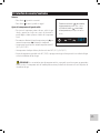
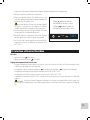
12. User Interface/Controls
Power
• Press
button, the display will turn on
• Press
button again, the display will turn off
Setting the Output Water Temperature
• To set the temperature, first turn on a hot water faucet and allow
water to run through the heater. The digital display lights up and
shows the current temperature setting.
• To increase or lower the temperature setting, press
increase the
temperature or
to decrease the temperature.
• Temperature can be set to any temperature from 86°F (30°C) to
122°F (50°C).
• A comfortable temperature for bathing and showering is between
105°F (41°C) and 110°F (43°C).
• The recommended temperature setting is 118°F (48°C), which will deliver hot water for all household needs at a maximum water
flow rate.
CAUTION: A higher temperature setting is not recommended, as it can cause severe scalding injuries to children and elderly
persons. Higher temperatures also produce more scale buildup in water heating devices.
118
º
F
temp
Press button to raise the
temperature (up to 122°F / 50°C)
or Press button to lower the
temperature (as low as 86°F / 30°C)

16
Starting the system for the rst time
1. Press
button, to activate the heater to display outlet temperature.
2. With the water running through the unit, press
or to adjust the temperature.
Freezing Temperatures
If the ambient temperature falls below 32°F (0°C), protect the heater from potential damage. Power off the unit using the dedicated circuit
breaker on the main electrical panel. Open a faucet slightly to cause water to flow continuously through the device at a very low rate,
without heating. Restore power to the unit when temperature condition is normal.
If the water inside the heater freezes, it can cause damage that is not covered by warranty. If you suspect water has frozen within
the unit, do not turn it on until you are sure the frozen water has melted, and there are no leaks in the unit. It is recommended to contact a
qualified electrician or the manufacturer for service in this situation.
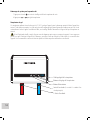
118
º
F
temp
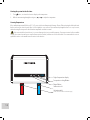
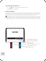
Digital temperature display
Temperature setting Buttons
Power Button
Cold water inlet
Hot water outlet
(to be connected to the main hot water pipe)

17
Digital temperature display
Temperature setting Buttons
Power Button
Cold water inlet
Hot water outlet
(to be connected to the main hot water pipe)
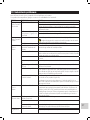
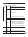
13. Troubleshooting
Before calling for service, check the troubleshooting list of common issues.
If you are unable to resolve a problem, contact your locally authorized distributor.
PROBLEM ISSUE POSSIBLE CAUSE SOLUTION
No hot water and
display do NOT
light up
Power outage or faulty wiring. Check the power supply. Check the circuit breakers.
Make sure the breakers at main electrical panel are ON. You may have a faulty
breaker or unit may be wired incorrectly.
Make sure the shutoff valve on the unit’s incoming water supply line is fully
open.
The flow rate needed to
activate the heating element
(0.5 gpm) has not been
reached.
Increase the flow rate from the water supply source.
Clean the filter screen on the unit’s water inlet.
No hot water
and display DOES
light up
Reset the unit Refer to manual (Page 18) for diagram of reset points.
Make sure to shut all power on your breaker panel before attempting to
reset unit. All resets must be pressed.
Potential internal part failure Please call us for further technical assistance.
Water is heated,
but not hot
enough.
The water flow rate exceeds the
heating capacity of the heater.
Reduce the water flow rate at the faucet or slightly close the shutoff valve on the
unit’s incoming water supply line to reduce the water flow rate.
Voltage less than 240 Volts The heating elements on your water heater are designed for 240 volts. When
used with a lower voltage, they produce less heating power. You may need to
upgrade to a larger input heater.
Crossed Wires. If it’s a new installation, double check the wiring to confirm that it is correct.
Temperature setting is too low. Increase the temperature setting on the unit.
Water pressure is less than 0.5
bar (7 psi).
Make sure the shutoff valve is fully open, and the water supply line is not
blocked.
Mixing too much cold water You do not need to mix as much cold water with your tankless water heater
compared to when you use a conventional water heater. You may also have an
anti- scald feature on your faucet that is mixing cold water. These types of faucets
can usually be adjusted to reduce the amount of cold water mixed.
Thermal loss due to long pipe
run.
As the hot water from the heater runs through the hot water delivery system to
your faucet, some heat will be lost especially if it has long distance to travel or
the pipes are cold. This is normal. You can compensate for this by increasing the
setting on your water heater if you need/ want hotter water.
Water is heated,
but not hot
enough.
Voltage less than 240 Volts The computer chips in your tankless water heater are programmed with the
expectation that your incoming line voltage is 240 volts. If you have less than
240 volts [i.e. 208V or 220V], it may affect the reading on your water heater’s
digital display and cause it to read slightly higher than the actual output
temperature. To compensate for this, increase the setting on your water heater if
you need or want hotter water.
Water is too hot. The water flow rate through
the heater is too slow.
Increase the flow rate at the water outlet.
Temperature setting is too high Switch to a lower temperature setting.
Water Temperature at faucet is
too hot.
Check for too little flow, or if the set point temperature is too high. This could
possibly indicate a possible internal part failure. Call us for technical assistance.

18
Heater shuts off
during use.
Power outage or faulty wiring. Check the power supply. Check the circuit breakers.
If the problem persists, please call us for further technical assistance.
Water stops
flowing.
Possible Blockage in water
pipes or hoses.
Make sure the main water line valve is fully open, and there are no obstructions
in the water supply line.
Water
temperature
varies from hot to
cold during use.
Water pressure has dropped
below a minimum level.
Increase the flow rate from the water supply source.
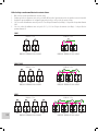
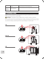
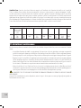
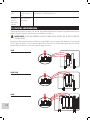
14. Reset Unit
As with all electrical appliances, it is crucial to first shut off all power to the unit directly at the fuse or breaker box before attempting to
reset this water heater.
WARNING: SERIOUS BODILY INJURY OR DEATH COULD OCCUR IF YOU IGNORE THIS WARNING.
Locate the three reset button locations as shown below and press all buttons. If you hear a “click,” the unit has reset. If you find that the unit
needs to be reset quite often, please call our customer service for further assistance. Proceed to turn on your breakers and power on the unit.
18kW
24kW, 29kW
36kW

19
LIMITED WARRANTY
For service, repair or any questions regarding your water heater, call the appropriate 800 number listed within this section. Please DO NOT
return the product to the place of purchase. Also, DO NOT mail the product back to the manufacturer, nor bring it to a service center without
proper instructions and permission from one of our representatives.
The terms of this warranty are solely subject to the original owner and are at no time transferable. A transfer of ownership will result in
immediate termination of this warranty. This warranty is valid only if the product is purchased from an authorized reseller that has an
established direct relationship with the manufacturer.
The manufacturer warrants to the original owner that our instant water heaters will be free from defect in workmanship and material for
TWO YEARS from the date of purchase, and free from leakage for SEVEN YEARS from the date of purchase. Should any part(s) prove to be
defective during this period, the manufacturer will only be responsible for a replacement water heater or replacement of the defective
part(s). The manufacturer is not responsible for labor charges or any incidental or consequential expenses. If a replacement water heater or
part is not available, the manufacturer’s liability is limited to the cost of the water heater or $1,000.00, whichever is less. The manufacturer
is not an insurer, and the original owner should purchase insurance to cover damage to property or belongings. The original owner agrees
to waive their right to jury trial or to participate in a class action. Also, the original owner agrees to waive subordination to the extent a loss
is covered by insurance, so that their insurance company cannot proceed with action against the manufacturer for recovery of any claims.
Furthermore, all requests must be arbitrated in the state of New Jersey.
Should the owner wish to return the water heater for repair, the owner must first secure written authorization from the manufacturer. The
owner shall be required to show proof of purchase date and to pay all transportation costs to return the defective part(s) or water heater for
repair or replacement. Warranty is void if: (i) water heater has been installed or used improperly; (ii) design has been altered in any way; (iii)
water heater has been installed and/or serviced by someone other than a licensed electrician; (iv) or if the water heater has been installed
or used in contradiction to installation instructions, applicable laws and/or ordinances.
CRAFTSMAN®
is a registered trademark of Stanley Black & Decker, Inc., used under license.
es una marca registrada de Stanley Black & Decker, Inc., utilizada bajo licencia.
est une marque déposée de Stanley Black & Decker, Inc., utilisée sous licence.
© 2020 CRAFTSMAN
Product manufactured by: (or “distributed by”)
Producto fabricado por:
Produit fabriqué par:
PARAGON GROUP USA LLC.
Englewood, New Jersey, 07631, USA
U.S. & Canada Only • É.-U. et Canada seulement
www.CRAFTSMAN.com • 888-331-4569

Notes:
P.N. 107336
La page est en cours de chargement...
La page est en cours de chargement...
La page est en cours de chargement...
La page est en cours de chargement...
La page est en cours de chargement...
La page est en cours de chargement...
La page est en cours de chargement...
La page est en cours de chargement...
La page est en cours de chargement...
La page est en cours de chargement...
La page est en cours de chargement...
La page est en cours de chargement...
La page est en cours de chargement...
La page est en cours de chargement...
La page est en cours de chargement...
La page est en cours de chargement...
La page est en cours de chargement...
La page est en cours de chargement...
La page est en cours de chargement...
La page est en cours de chargement...
La page est en cours de chargement...
La page est en cours de chargement...
La page est en cours de chargement...
La page est en cours de chargement...
La page est en cours de chargement...
La page est en cours de chargement...
La page est en cours de chargement...
La page est en cours de chargement...
La page est en cours de chargement...
La page est en cours de chargement...
La page est en cours de chargement...
La page est en cours de chargement...
La page est en cours de chargement...
La page est en cours de chargement...
La page est en cours de chargement...
La page est en cours de chargement...
La page est en cours de chargement...
La page est en cours de chargement...
La page est en cours de chargement...
La page est en cours de chargement...
-
 1
1
-
 2
2
-
 3
3
-
 4
4
-
 5
5
-
 6
6
-
 7
7
-
 8
8
-
 9
9
-
 10
10
-
 11
11
-
 12
12
-
 13
13
-
 14
14
-
 15
15
-
 16
16
-
 17
17
-
 18
18
-
 19
19
-
 20
20
-
 21
21
-
 22
22
-
 23
23
-
 24
24
-
 25
25
-
 26
26
-
 27
27
-
 28
28
-
 29
29
-
 30
30
-
 31
31
-
 32
32
-
 33
33
-
 34
34
-
 35
35
-
 36
36
-
 37
37
-
 38
38
-
 39
39
-
 40
40
-
 41
41
-
 42
42
-
 43
43
-
 44
44
-
 45
45
-
 46
46
-
 47
47
-
 48
48
-
 49
49
-
 50
50
-
 51
51
-
 52
52
-
 53
53
-
 54
54
-
 55
55
-
 56
56
-
 57
57
-
 58
58
-
 59
59
-
 60
60


Craftsman CM-XTEPA0029 Manuel utilisateur
- Taper
- Manuel utilisateur
- Ce manuel convient également à
dans d''autres langues
- English: Craftsman CM-XTEPA0029 User manual
- español: Craftsman CM-XTEPA0029 Manual de usuario
- português: Craftsman CM-XTEPA0029 Manual do usuário
Autres documents
-
ATMOR AT-912-36TP Manuel utilisateur
-
Rheem RETEX-36 Manuel utilisateur
-
Ariston AURES PRO 36 240V US Manuel utilisateur
-
Ariston AURES PRO 36 240V US Manuel utilisateur
-
BLACK+DECKER BD-11-DWH Manuel utilisateur
-
-
Link2Home EM-TXC142B Mode d'emploi
-
Black and Decker BD-11-DWH Manuel utilisateur
-
EcoSmart FSA NFSML Manuel utilisateur
-
Bradley Keltech SNAR-126 Guide d'installation