
Insteon Dimmer Module
Owner’s Manual
Insteon Dimmer Module
Owner’s Manual

Contents
Getting Started
Insteon Dimmer Module 4
Device Overview
Buttons
Installation
Leave Your Lamp On
Insteon Links
Understanding Linking 6
Links are One-Way
Links Remember a Device’s State
Controllers
Responders
Controller-Only 7
Responder-Only
Grouping Devices
Use Cross Linking
Insteon Hub
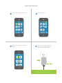
Linking to the Insteon Hub 9
Manual Linking
Linking with a Single-Button Controller 11
Linking with a Multi-Button Controller 12
Multi-Linking or Making a Scene 13
Unlinking from a Single-Button Controller 14
Unlinking from a Multi-Button Controller 15
Multi-Unlinking or Removing a Scene 16
Local Programming
About Local Programming 18
Load Sense 19
Hardware Reset
Factory Reset 21
Software-Only Features
Beep on Button Press 23
Disable Local Programming
Blink on Trac
Error Blink
Appendix
Specications 26
Troubleshooting 29
Certications and Warnings 31
Product Warranty 32

3
Everything you need to quickly get up and running.
Getting Started
Everything you need to quickly get up and running.
Getting Started

4
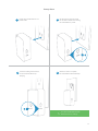
Leave Your Lamp OnInstallation
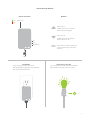
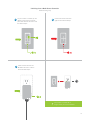
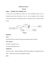
ButtonsDevice Overview
Insteon Dimmer Module
Set Button
On
O
Status LEDOn
O
®
Plug your lamp into the bottom of the
Dimmer Module and plug the Dimmer Module
into an unswitched wall outlet.
Tap to turn o
Double-tap to turn o instantly
Press and hold to dim
Tap to turn on
Double-tap to turn on instantly
Press and hold to brighten
See sections on Basic Linking and
Local Programming for set button
functions
®
If your lamp’s switch is OFF, the Dimmer Module
will be unable to remotely control your lamp.
ON

5
Insteon devices can stand alone and function as a local switch or dimmer,
but their real power comes when they are connected together to form a
control system. Most Insteon devices can control one another and be the
recipient of control. The process of associating multiple Insteon devices to
one another is called Linking.
Insteon Links

6
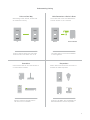
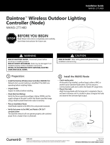
When linking Insteon devices, the links that
are created are one-way.
The current state of the controlled device is
stored in the link: on, o or dimmed.
Switch A will turn Switch B on and o but
Switch B cannot turn Switch A on or o.
The switch will turn on the Dimmer Module
to 75% brightness.
A SwitchB Dimmer Module
NEW
X
NEW
X
75%
Insteon devices that can turn other devices on
or o are called controllers.
Sensors, Switches, Keypads and the
Hub are common controllers.
NEW
X
Insteon devices that receive the command of a
controller are called responders.
Switches, LED Bulbs, Plug-In Modules and
Micro Modules are common responders.
NEW
X
RespondersControllers
Links Remember a Device’s StateLinks are One-Way
Understanding Linking
Neutral
On
Off
Set
N
N
Load L1
Line L

7
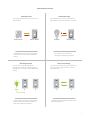
Controller-Only
Some devices like sensors can only control
other devices.
The Motion Sensor will turn on the Switch
but the switch cannot control the Motion
Sensor.
Motion Sensor
NEW
X
X
Responder-Only
Some devices cannot control other devices;
these devices only receive Insteon commands.
Some devices can only link as
responders to devices and scenes.
LED Bulb Dimmer SwitchDimmer Switch
NEW
X
X
Understanding Linking
Grouping Devices Use Cross Linking
You may want to group together two
devices, for example, in a virtual-three way
conguration. For Insteon, this is called Cross
Linking.
To Cross Link, simply turn on the devices and
perform the linking process twice, once in
each direction.
To group Switch A and B so that they each
control one another and the connected
load, Cross Linking is necessary.
Link Switch A to Switch B and repeat to link
Switch B to Switch A.
NEW
X
NEW
X
A AB BLoad

8
The Insteon Hub allows you to congure your device, customize its
properties, create scenes and more, all from your smartphone or tablet.
Insteon Hub
The Insteon Hub allows you to congure your device, customize its
properties, create scenes and more, all from your smartphone or tablet.
Insteon Hub

9
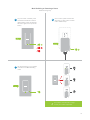
You can now control your Dimmer
Module from the Insteon Hub.
Linking to the Insteon Hub
1
4
From Rooms, navigate to All Devices.
When prompted, press and hold the
set button on your Dimmer Module
until the device double-beeps.
®
Rooms
All Devices Check-In Favorites
Bathroom Bedroom Hallway
Kitchen Living Room Outside
72º
Add Device
Plug-In Module Wired In
LED Bulb Thermostat
3
Select Plug-In Module form the list of
devices.
2
Tap the Add button.
All Devices
Back Door Bathroom Bedroom
Font Door Garage Door Garage Light
Motion Sensor Outside Lights
72º
Add

10
When not using a central controller like the Insteon Hub, Insteon devices
can be congured and linked manually on a device-to-device basis. It is
strongly advised that you not perform manual linking when using a central
controller. Instead, let your central controller handle the linking for you.
Manual Linking

11
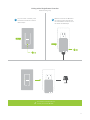
Linking with a Single-Button Controller
2
Make sure the Dimmer Module is
On and then press and hold the
Dimmer Module’s set button until
the device double-beeps.
1
On your Insteon controller, press
and hold the set button until the
device beeps.
Manual Linking Only
®
®
Your Insteon controller will now
control your Dimmer Module.

12
A
B
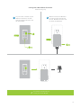
Linking with a Multi-Button Controller
2
Make sure the Dimmer Module is
On and then press and hold the
Dimmer Module’s set button until
the device double-beeps.
1
On your Insteon controller, tap the
desired control button and then
press and hold the set button until
the device beeps.
®
®
Your Insteon controller will now
control your Dimmer Module.
Manual Linking Only

13
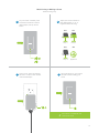
Multi-Linking or Making a Scene
2
3 4
Adjust your scene members to
their desired state: on, o, or
brightness level if dimming.
Lamp 1
Lamp 3
Lamp 2
Appliance
One at a time, press and hold the
set button on each scene member
until it double-beeps.
Tap the set button on your Insteon
controller to nish building your
scene.
1
On your Insteon controller, press
and hold the set button until the
device beeps, then tap the set
button.
50% 72%
30%
ON
®
A
B
Your Insteon controller will now
control your scene.
Manual Linking Only

14
Unlinking from a Single-Button Controller
1
On your Insteon controller, press
and hold the set button until the
device beeps.
2
Press and hold the set button
again until the device beeps.
3
Press and hold the Dimmer
Module’s set button until the
device double-beeps.
®
®
X
Your Insteon controller will no longer
control your Dimmer Module.
Manual Linking Only

15
A
B
1
On your Insteon controller, tap the
desired control button and then
press and hold the set button until
the device beeps.
Unlinking from a Multi-Button Controller
2
Press and hold the set button
again until the device beeps.
3
Press and hold the Dimmer
Module’s set button until the
device double-beeps.
®
®
X
Your Insteon controller will no
longer control your Dimmer Module.
Manual Linking Only

16
Multi-Unlinking or Removing a Scene
2
3
One at a time, press and hold the
set button on each scene member
until it double-beeps.
Tap the set button on your Insteon
controller to exit Multi-Unlinking
mode.
1
On your Insteon controller, press
and hold the set button until the
device beeps. Press and hold the
set button again, then tap the set
button.
®
A
B
C
®
®
®
X
Your Insteon controller will no longer
control your Insteon responders.
Manual Linking Only

17
Use the local programming to set local on-level, ramp rates and even
perform a factory reset.
Local Programming
Use local programming to set local on-level, ramp rates and even perform
a factory reset.
Local Programming

18
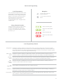
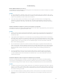
About Local Programming
Local Programming Features
Linking Mode Readies the module for linking to another Insteon device. As linking is directional, the rst device placed
into linking mode will become the controller in the controller/responder relationship. The second device will
become the responder. The device automatically exits linking mode after a link has been made with another
Insteon device or four minutes have elapsed without linking.
Multi-Linking
Mode
Readies the module for linking to multiple Insteon devices. The module will remain in linking mode for 4
minutes or until the module’s set button is tapped. This mode is very usefully for manually creating scenes.
Unlinking
Mode
Allows the removal of links from the Insteon device. The device will automatically exit unlinking mode after a
link has been removed from another Insteon device or four minutes have elapsed without linking.
Multi-
Unlinking
Mode
Allows the removal of multiple links from the Insteon device. The device will stay in unlinking mode for 4
minutes or until the device’s set button is tapped.
LED
Brightness
Allows adjusting the brightness level of the module’s status LED.
RF Beacon Places the device in a mode that broadcasts a signal over Insteon RF. Any devices beeping or displaying a
blinking LED are within range of the module’s RF signal.
Factory Reset Erases any user-customized programming from the device including all Insteon device links, scenes, ramp
rate, on-level, etc. A factory reset cannot be undone.
To move right, press and
hold the set button
To move down, tap the set
button
Status LED blinks green
Status LED double-blinks
green
Status LED blinks red
Status LED double-blinks
red
The Local Programming Flowchart is a visual
representation of the device’s settings. Many
device features can be congured using this
diagram. Some devices have more options
than others but the Local Programming
Flowchart presents even the most
complicated devices with a straightforward,
navigable path.
If using the Insteon Hub or any other central
controller, it is strongly advised that you
not use Local Programming. Your central
controller can manage the device properties
and links for you.
Navigation Local Programming
Using a Central Controller
NEW
X

19
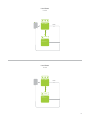
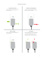
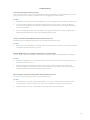
Load Sense
Load Sense
Linking Mode
Linking Mode
Disable
Load Sense
SOLID
Enable
Load Sense
SOLID
Press
Press
Tap 2x Tap 3x
Exit
Exit
Disable
Enable

20
Chapter explanation
Chapter Title
A factory reset will erase all links stored in the device’s database as well as
any customized properties.
Hardware Reset
A factory reset will erase all links stored in the device’s database as well as
any customized properties.
Hardware Reset
La page est en cours de chargement...
La page est en cours de chargement...
La page est en cours de chargement...
La page est en cours de chargement...
La page est en cours de chargement...
La page est en cours de chargement...
La page est en cours de chargement...
La page est en cours de chargement...
La page est en cours de chargement...
La page est en cours de chargement...
La page est en cours de chargement...
La page est en cours de chargement...
-
 1
1
-
 2
2
-
 3
3
-
 4
4
-
 5
5
-
 6
6
-
 7
7
-
 8
8
-
 9
9
-
 10
10
-
 11
11
-
 12
12
-
 13
13
-
 14
14
-
 15
15
-
 16
16
-
 17
17
-
 18
18
-
 19
19
-
 20
20
-
 21
21
-
 22
22
-
 23
23
-
 24
24
-
 25
25
-
 26
26
-
 27
27
-
 28
28
-
 29
29
-
 30
30
-
 31
31
-
 32
32


INSTEON Dimmer Module Manuel utilisateur
- Taper
- Manuel utilisateur
- Ce manuel convient également à
dans d''autres langues
- English: INSTEON Dimmer Module User manual
Documents connexes
-
INSTEON 2663-222 Manuel utilisateur
-
-
-
-
-
-
-
-
-
Autres documents
-
Rhine Electronics 7262T6 Ceiling Fan Controller Manuel utilisateur
-
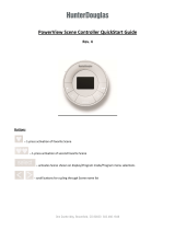 Hunter Douglas Window Fashions UXUSC4U1 Manuel utilisateur
-
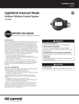
 Lightgrid Internal Node Guide d'installation
-
 GE current CTRL042 Guide d'installation
-
 Ningbo Everflourish Smart Technology ED26WF-2US1 Dimmer Switch Manuel utilisateur
-
GE Appliances CTRL044 Guide d'installation
-
 Daintree WANSI Wireless Area Controller Guide d'installation
-
Checkpoint Systems YWZ-HB-PRICETAG Manuel utilisateur


