
Smart On/Off Switch Manual
Federal Communications Commission (FCC) Statement
FCC Caution: Any changes or modifications not expressly approved by the party responsible for
compliance could void the user’s authority to operate this equipment.
This device complies with Part 15 of the FCC Rules. Operation is subject to the following two
conditions: (1) This device may not cause harmful interference, and (2) this device must accept any
interference received, including interference that may cause undesired operation.
NOTE: This equipment has been tested and found to comply with the limits for a Class B digital device,
pursuant to Part 15 of the FCC Rules. These limits are designed to provide reasonable protection
against harmful interference in a residential installation. This equipment generates, uses and can
radiate radio frequency energy and, if not installed and used in accordance with the instructions,
may caus harmful interference to radio communications.However, there is no guarantee that
interference will not occur in a particular installation. If this equipment does cause harmful interference
to radio or television reception, which can be determined by turning the equipment off and on,
the user is encouraged to try to correct the interference by one or more of the following measures:
Reorient or relocate the receiving antenna.Increase the separation between the equipment and
receiver.Connect the equipment into an outlet on a circuit different from that to which the receiver
is connected.Consult the dealer or an experienced radio/TV technician for help.This equipment Smart On/Off Switch
should be installed and operated with minimum distance 20cm between the radiator and your body.
IC Caution:
This device complies with Industry Canada licence-exempt RSS standard(s). Operation is subject
to the following two conditions: (1) this device may not cause interference, and (2) this device must
accept any interference, including interference that may cause undesired
operation of the device.
DECLARATION DE CONFORMITE D'INDUSTRIE CANADA
Ce périphérique a été testé et reconnu conforme aux limites spécifiées dans RSS-210.
Son utilisation est soumise aux deux conditions suivantes :
(1) il ne doit pas provoquer d'interférences gênantes et
(2) il doit tolérer les interférences re.ues, notamment cellessusceptibles d'en perturber le fonctionnement.
WARRANTY
Evalogik Products warrants this product to be free from manufacturing defects for
a period of two years from the original date of consumer purchase. This warranty is limited
to the repair or replacement of this product only and does not extend to consequential or
incidental damage to other products that may be used with this product.
This warranty is in lieu of all other warranties, expressed or implied. Some states do not
allow limitations on how long an implied warranty lasts or permit the exclusion or limitation
of incidental or consequential damage, so the above limitations may not apply to you.
This warranty gives you specific rights, and you may also have other rights which vary from
state to state. if the unit should prove defective within the warranty period.
SPECIFICATIONS WARNING
Model:MS10ZS RISK OF FIRE
Power: 120 VAC, 60 Hz. RISK OF ELECTRICAL SHOCK
Signal (Frequency): 908.42 MHZ. RISK OF BURNS
Maximum load for outlet 15A, 960W Resistive CONTROLLING APPLIANCES:
Maximum load for the Z-Wave™ controlled outlet: EXERCISE EXTREME CAUTION WHEN USING Z-Wave™ DEVICES TO CONTROL
600W Incandescent, ½ HP Motor or 600W Resistive APPLIANCES. OPERATION OF THE Z-Wave™ DEVICE MAY BE IN A DIFFERENT
Range: Up to 100 feet line of sight between the Wireless
Controller
ROOM THAN THE CONTROLLED APPLIANCE, ALSO ANUNINTENTIONAL ACTIVATION
and the closest Z-Wave™ receiver module. MAY OCCUR IF THE WRONG BUTTON ON THE REMOTE IS PRESSED. Z-Wave™ DEVICES
Operating Temperature Range: 32-104° F (0-40° C) MAY AUTOMATICALLY BE POWERED ON DUE TO TIMED EVENT PROGRAMMING.
DEPENDING UPON THE APPLIANCE, THESE UNATTENDED OR UNINTENTIONAL
Specifications subject to change without notice OPERATIONS COULD POSSIBLY RESULT IN A HAZARDOUS CONDITION. FOR THESE
due to continuing product improvement REASONS, WE RECOMMEND DO NOT RETURN THIS PRODUCT TO THE STORE
THE FOLLOWING:
Website:www.nie-tech.com DO NOT USE Z-Wave™ DEVICES TO CONTROL ELECTRIC
HEATERS OR ANY OTHER APPLIANCES WHICH MAY PRESENT
A HAZARDOUS CONDITION DUE TO UNATTENDED OR
UNINTENTIONAL OR AUTOMATIC POWER ON CONTROL.

Introduction:
This product can be operated in any Z-Wave network with other Z-Wave Plus™ certified devices from other manufacturers.
All non-battery operated nodes within the network will act as repeaters regardless of vendor to increase reliability of the network.
Each module is designed to act as a repeater,which will re-transmit a radio frequency (RF) signal by routing the signal
around obstacles and radio dead spots to ensure that the signal is received at its intended destination.
MS10ZS is a security enabled Z-Wave Plus™ device. A security Enabled Z-Wave Plus™ Controller must be used in order to fully utilize the product.
The Device Type of the MS10ZS is on/off power switch.
The Role Type of the MS10ZS is Always On Slave Role Type
Key
Features
:
---Remote ON/OFF control via the Z-Wave™ controller
---Manual ON/OFF control with the front panel push button
---Support Association Group and Auto Report switch status
---Support firmware upgrades via Over-the-air (need Gateways support)
---Support Scenes
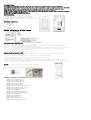
Product Overview:
A. Up Push button
B. Down Push button
C. Load1 (Black)
D. Lin (Black) - Line in
E. Nin (White) - Nutral in
F. 3-way (RED)
MS10ZS Installation Wiring Diagram
Key function description
Function 1: Press the up or down button to turn the output ON or OFF
Function 2: quickly press 3x upper paddle: inclusion (only if switch is not included in network)quickly press 3x lower paddle: exclusion
Function 3: quickly press upper paddle 6x to change Status LED Configuration
Function 4: Press and hold lower paddle for 10 seconds,then LED starts blinking, release paddle and within 2 seconds,click lower paddle 5 times
(Node:Please use this procedure only when the network primary controller is missing or otherwise inoperable.)
Function 5: Tap A(1x/2x/3x/4x/5x/Hold/Release) Activate the scene.
Function 6: Tap B(1x/2x/3x/4x/5x/Hold/Release) Activate the scene.
Adding Your Device To A Hub
The device support two methods of inclusion,When using a Z-Wave Plus™ certified controller choose Network Wide Inclusion or SmartStart,
Network Wide Inclusion To A Z-Wave™ Network
1,Refer to your primary controller instructions to process the inclusion / exclusion setup procedure.
2,When prompted by your primary controller, click the Up or Down button three times in one second.
The device is compatible with SmartStart
SmartStart enabled products can be added into a Z-Wave™ network by scanning the Z-Wave QR Code found on the top of the outlet or the back of
the box with a controller providing SmartStart inclusion.No further action is required and the SmartStart product will be added automatically within
10 minutes of being switched on and in the network vicinity.
QR
CODE
the QR code are sticked to the side of the case,DSK is included in the QR code.
DSK
The DSK code can be found on the DSK label which is attached on the packaging box.
Z
-
Wave
™
protocol
Command
Class
Node
Info
COMMAND_CLASS_ZWAVEPLUS_INFO_V2,
COMMAND_CLASS_SWITCH_BINARY_V2,
COMMAND_CLASS_CONFIGURATION_V4,
COMMAND_CLASS_CENTRAL_SCENE_V3,
COMMAND_CLASS_ASSOCIATION_V3,
COMMAND_CLASS_MULTI_CHANNEL_ASSOCIATION_V3,
COMMAND_CLASS_ASSOCIATION_GRP_INFO_V3,
COMMAND_CLASS_TRANSPORT_SERVICE_V2,
COMMAND_CLASS_VERSION_V3,
COMMAND_CLASS_MANUFACTURER_SPECIFIC_V1,
COMMAND_CLASS_DEVICE_RESET_LOCALLY_V1,
COMMAND_CLASS_INDICATOR_V3,
COMMAND_CLASS_POWERLEVEL_V1,
COMMAND_CLASS_SECURITY_2,
COMMAND_CLASS_SUPERVISION_V1,
COMMAND_CLASS_FIRMWARE_UPDATE_MD_V5
A
B
C
DE
F

The Below listed Command Class are all supported the Security S2
COMMAND_CLASS_VERSION_V2,
COMMAND_CLASS_SWITCH_BINARY_V2,
COMMAND_CLASS_CONFIGURATION_V4,
COMMAND_CLASS_CENTRAL_SCENE_V3,
COMMAND_CLASS_ASSOCIATION_V3,
COMMAND_CLASS_MULTI_CHANNEL_ASSOCIATION_V3,
COMMAND_CLASS_ASSOCIATION_GRP_INFO_V3,
COMMAND_CLASS_MANUFACTURER_SPECIFIC_V1,
COMMAND_CLASS_DEVICE_RESET_LOCALLY_V1,
COMMAND_CLASS_INDICATOR_V3,
COMMAND_CLASS_POWERLEVEL_V1,
COMMAND_CLASS_FIRMWARE_UPDATE_MD_V5
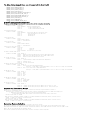
Z-Wave™ Configuration Parameters
You may use the below configuration parameters to change settings of the corresponding functionality.
1: Locally Button function
Paramter No: 1(0x01) Size:1 Byte
Value: 00(default) Up Button ON,Down Button OFF
Value: 01 Up Button OFF,Down Button ON
Value: 02 Up Button ON/OFF,Down Button ON/OFF
2:Status LED Configuration
Paramter No: 2(0x02) Size:1 Byte
Value: 00(default) Output and the LED are in the different state.
Value: 01 Output and the LED are in the same state.
Value: 02 LED Always OFF
Value: 03 LED Always ON
3: Auto Turn-Off Timer
Paramter No: 3(0x03), Size=4,
Values:0 (minutes) default;
Values: 1 – 65535 (minutes);
5: Auto Turn-Off Timer
Paramter No: 5(0x05), Size=4,
Values:0 (minutes) default;
Values: 1 – 65535 (minutes);
8:Restores state after power failure
Paramter No: 8(0x08) Size:1 Byte
Value: 00 Output OFF.
Value: 01 Output ON.
Value: 02 (default) The state before a power outage.
11: Enable or Disable OutPut control
Paramter No: 11(0x0B), Size=1,Default =1
Value=0 disable local button and External Switch control,enable Z-Wave™ control
Value=1 enable local button and External Switch control,enable Z-Wave™ control
Value=2 disable local button and External Switch control
12: external switch type
Paramter No: 12(0x0C) Size:1 ,Default =0
Value: 0 toggle switch(device changes status when switch changesstatus)
Value: 01 momentary switch
Value: 02 electronic add-on switch
13: Behavior when Output control disabled
Paramter No: 13(0x0D) Size:1 ,Default =0
Value: 0 Report on/off status and change LED indicator
when upper or lower paddle is pressed and Parameter 11 is set to value 0 or 2 (output control disabled).
Value: 01 DON’t report on/off status or change LED indicator
when upper or lower paddle is pressed and Parameter 11 is set to value 0 or 2 (output control disabled).
14: LED Indicator Color
Paramter No: 14(0x0E) Size:1 ,Default =1
Value: 0 White
Value: 01 Blue
Value: 02 Green
Value: 03 Red
15: LED Indicator Brightness
Paramter No: 15(0x0F) Size:1 ,Default =1
Value: 00 Bright (100%)
Value: 01 Medium (60%)
Value: 02 Low (30%)
16: Association reports
Paramter No: 16(0x10) Size:1 ,Default =1
Value: 00 Z-Wave™control:Binary switch report,Manualcontrol:Basic setreport
Value: 01 Z-Wave™control:Binary switch report,Manualcontrol: Binary switch report
Support for Association Groups
MS10ZS supports 3 association groups. Group 1 supports 1 node ID,Group 2 and Group 3 Supports maximum of 5 node ID’s
Association group_1:Z-Wave™ Plus Lifeline
Association group_1 is default to associate with the primary controller (Gateway/Hub/Controller) for MS10ZS Status change report,
1. MS10ZS will trigger AUTO report function if the Switch status had been changed.
(ex.Switch Binary Report/Basic Report/Central Scene Notification/ Device Reset Locally Notification)
Association group_2:basic set command
When the output of the MS10ZS is changed, On (0xFF) or Off (0x00). The MS10ZS will automatically send out a related basic set
command. On (0xFF) or Off (0x00) to its associated group.
Association group_3:basic set command
When the output of the MS10ZS is changed, On (0xFF) or Off (0x00). The MS10ZS will automatically send out a related basic set
command. On (0xFF) or Off (0x00) to its associated group.
Restoring Factory Defaults
MS10ZS is removed from the network and will be restored to the factory setting
All Configuration Parameters values and Association information will be restored to factory default settings and excluded from the network.
Manual Reset:Press and hold lower paddle for 10 seconds, then LED starts blinking, release paddle and within 2 seconds, click lower paddle 5 times
Remark : All the setting and data will be permanently deleted.
Please use this procedure only when the network primary controller is missing or otherwise inoperable.
-
 1
1
-
 2
2
-
 3
3


dans d''autres langues
- English: Minoston MS10ZS Installation guide
Documents connexes
Autres documents
-
QOLSYS QZ2142-840 Manuel utilisateur
-
EVA LOGIK ZW97 Manuel utilisateur
-
 Show Home ZW32 Manuel utilisateur
-
 Show Home ZW96 Manuel utilisateur
-
Ring Contact Sensor v2 Manuel utilisateur
-
-
Aeotec ZWA009 Mode d'emploi
-
Shelly Wave Manuel utilisateur
-
-
iDevices 61304/ZW1002 Manuel utilisateur

