Bostitch Nail Gun RN45B Manuel utilisateur
- Catégorie
- Cloueuse
- Taper
- Manuel utilisateur
Ce manuel convient également à

OPERATION and MAINTENANCE MANUAL
MANUAL DE OPERACIÓN Y DE MANTENIMIENTO
MANUEL D’INSTRUCTIONS ET D’ENTRETIEN
RN45B
COIL-FED PNEUMATIC ROOFING NAILER
CLAVADORA NEUMÁTICA ALIMENTADA POR ROLLO PARA TECHADO
CLOUEUR PNEUMATIQUE À ENROULEMENT POUR TOITURE
103280REVG 11/05
BEFORE OPERATING THIS TOOL, ALL OPERATORS SHOULD STUDY THIS MANUAL TO
UNDERSTAND AND FOLLOW THE SAFETY WARNINGS AND INSTRUCTIONS. KEEP THESE
INSTRUCTIONS WITH THE TOOL FOR FUTURE REFERENCE. IF YOU HAVE ANY QUESTIONS,
CONTACT YOUR BOSTITCH REPRESENTATIVE OR DISTRIBUTOR.
ANTES DE OPERAR ESTA HERRAMIENTA, TODOS LOS OPERADORES DEBERÁN ESTUDIAR
ESTE MANUAL PARA PODER COMPRENDER Y SEGUIR LAS ADVERTENCIAS SOBRE
SEGURIDAD Y LAS INSTRUCCIONES. MANTENGA ESTAS INSTRUCCIONES CON LA
HERRAMIENTA PARA FUTURA REFERENCIA, SI TIENE ALGUNA DUDA, COMUNÍQUESE CON
SU REPRESENTANTE DE BOSTITCH O CON SU DISTRIBUIDOR.
LIRE ATTENTIVEMENT LE PRÉSENT MANUEL AVANT D’UTILISER L’APPAREIL. PRÉTER UNE
ATTENTION TOUTE PARTICULIÈRE AUX CONSIGNES DE SÉCURITÉ ET AUX
AVERTISSEMENTS. GARDER CE MANUEL AVEC L’OUTIL POUR FUTUR RÉFÉRENCE. SI
VOUS AVEZ DES QUESTIONS, CONTACTEZ VOTRE REPRÉSENTANT OU VOTRE
CONCESSIONNAIRE BOSTITCH.
STANLEY FASTENING SYSTEMS L.P.

-2-
INTRODUCTION
The Bostitch RN45B is a precision-built tool, designed for high speed, high volume nailing. These tools will
deliver efficient, dependable service when used correctly and with care. As with any fine power tool, for
best performance the manufacturer’s instructions must be followed. Please study this manual before
operating the tool and understand the safety warnings and cautions. The instructions on installation,
operation and maintenance should be read carefully, and the manual kept for reference. NOTE: Additional
safety measures may be required because of your particular application of the tool. Contact your Bostitch
representative or distributor with any questions concerning the tool and its use. Bostitch, Inc., East
Greenwich, Rhode Island 02818.
INDEX
Safety Instructions . . . . . . . . . . . . . . . . . . . . . . . . . . . . . . . . . . . . . . . . . . . . . . . . . 3
Tool Specifications . . . . . . . . . . . . . . . . . . . . . . . . . . . . . . . . . . . . . . . . . . . . . . . . . 4
Air Supply: Fittings, Hoses, Filters, Air Consumption, Regulators,
Operating Pressure, Setting Correct Pressure . . . . . . . . . . . . . . . . . . . . . . . . . . . . . 5
Lubrication . . . . . . . . . . . . . . . . . . . . . . . . . . . . . . . . . . . . . . . . . . . . . . . . . . . . . . 5
Loading the Tool . . . . . . . . . . . . . . . . . . . . . . . . . . . . . . . . . . . . . . . . . . . . . . . . . . 6
Tool Operation . . . . . . . . . . . . . . . . . . . . . . . . . . . . . . . . . . . . . . . . . . . . . . . . . 7 & 8
Maintaining the Pneumatic Tool . . . . . . . . . . . . . . . . . . . . . . . . . . . . . . . . . . . . . . . 9
Trouble Shooting . . . . . . . . . . . . . . . . . . . . . . . . . . . . . . . . . . . . . . . . . . . . . . . . . 10
Driver Maintenance/Directional Exhaust. . . . . . . . . . . . . . . . . . . . . . . . . . . . . . . . . 11
Accessories . . . . . . . . . . . . . . . . . . . . . . . . . . . . . . . . . . . . . . . . . . . . . . . . . . . . . 11
NOTE:
Bostitch tools have been engineered to provide excellent customer satisfaction and are designed to achieve
maximum performance when used with precision Bostitch fasteners engineered to the same exacting
standards. Bostitch cannot assume responsibility for product performance if our tools are used with
fasteners or accessories not meeting the specific requirements established for genuine Bostitch nails,
staples and accessories.
LIMITED WARRANTY — U.S. and Canada Only
Effective December 1, 2005 Bostitch, L.P. warrants to the original retail purchaser that the product purchased is free
from defects in material and workmanship, and agrees to repair or replace, at Bostitch’s option, any defective Bostitch
branded pneumatic stapler or nailer for a period of seven (7) years from date of purchase (one (1) year from the date
of purchase for compressors and tools used in production applications). Warranty is not transferable. Proof of
purchase date required. This warranty covers only damage resulting from defects in material or workmanship; it does
not cover conditions or malfunctions resulting from normal wear, neglect, abuse, accident or repairs attempted or
made by other than our national repair center or authorized warranty service centers. Driver blades, bumpers, o-rings,
pistons and piston rings are considered normally wearing parts. For optimal performance of your Bostitch tool always
use genuine Bostitch fasteners and replacement parts.
THIS WARRANTY IS IN LIEU OF ALL OTHER WARRANTIES, EXPRESS OR IMPLIED, INCLUDING BUT NOT
LIMITED TO THE IMPLIED WARRANTIES OF MERCHANTABILITY OR FITNESS FOR A PARTICULAR
PURPOSE. BOSTITCH SHALL NOT BE LIABLE FOR ANY INCIDENTAL OR CONSEQUENTIAL DAMAGES.
Some states and countries do not allow limitations on how long an implied warranty lasts, or the exclusion or limitation
of incidental or consequential damages, so the above limitations or exclusions may not apply to you. This warranty
gives you specific legal rights, and you may also have other rights which vary from state to state and country to country.
To obtain warranty service in the U.S. return the product, together with proof of purchase, to the U.S. Bostitch National
or Regional Independent Authorized Warranty Service Center. In the U.S. you may call us at 1-800-556-6696 or visit
www.BOSTITCH.com for the location most convenient for you. In Canada please call us at 800-567-7705 or visit
www.BOSTITCH.com

-3-
SAFETY INSTRUCTIONS
EYE PROTECTION which conforms to ANSI specifications and provides protection against
flying particles both from the FRONT and SIDE should ALWAYS be worn by the operator and
others in the work area when connecting to air supply, loading, operating or servicing this
tool. Eye protection is required to guard against flying fasteners and debris, which could
cause severe eye injury.
The employer and/or user must ensure that proper eye protection is worn. Eye protection
equipment must conform to the requirements of the American National Standards Institute,
ANSI Z87.1 and provide both frontal and side protection. NOTE: Non-side shielded
spectacles and face shields alone do not provide adequate protection.
CAUTION:
Additional Safety Protection will be required in some environments. For
example, the working area may include exposure to noise level which can lead to hearing
damage. The employer and user must ensure that any necessary hearing protection is
provided and used by the operator and others in the work area. Some environments will
require the use of head protection equipment. When required, the employer and user must
ensure that head protection conforming to ANSI Z89.1 is used.
AIR SUPPLY AND CONNECTIONS
Do not use oxygen, combustible gases, or bottled gases as a power source for this tool as
tool may explode, possibly causing injury.
Do not use supply sources which can potentially exceed 200 P.S.I.G. as tool may burst,
possibly causing injury.
The connector on the tool must not hold pressure when air supply is disconnected. If a
wrong fitting is used, the tool can remain charged with air after disconnecting and thus will
be able to drive a fastener even after the air line is disconnected possibly causing injury.
Do not pull trigger or depress contact arm while connected to the air supply as the tool may
cycle, possibly causing injury.
Always disconnect air supply: 1.) Before making adjustments; 2.) When servicing the tool;
3.) When clearing a jam; 4.) When tool is not in use; 5.) When moving to a different work
area, as accidental actuation may occur, possibly causing injury.
LOADING TOOL
When loading tool: 1.) Never place a hand or any part of body in fastener discharge area of
tool; 2.) Never point tool at anyone; 3.) Do not pull the trigger or depress the trip as
accidental actuation may occur, possibly causing injury.
OPERATION
Always handle the tool with care: 1.) Never engage in horseplay; 2.) Never pull the trigger
unless nose is directed toward the work; 3.) Keep others a safe distance from the tool while
tool is in operation as accidental actuation may occur, possibly causing injury.
The operator must not hold the trigger pulled on contact arm tools except during fastening
operation as serious injury could result if the trip accidentally contacted someone or
something, causing the tool to cycle.
Keep hands and body away from the discharge area of the tool. A contact arm tool may
bounce from the recoil of driving a fastener and an unwanted second fastener may be
driven possibly causing injury.
Check operation of the contact arm mechanism frequently. Do not use the tool if the arm
is not working correctly as accidental driving of a fastener may result. Do not interfere with
the proper operation of the contact arm mechanism.
Do not drive fasteners on top of other fasteners or with the tool at an overly steep angle as
this may cause deflection of fasteners which could cause injury.
Do not drive fasteners close to the edge of the work piece as the wood may split, allowing
the fastener to be deflected possibly causing injury.
This nailer produces SPARKS during operation. NEVER use the nailer near flammable
substances, gases or vapors including lacquer, paint, benzine, thinner, gasoline, adhesives,
mastics, glues or any other material that is -- or the vapors, fumes or byproducts of which are --
flammable, combustible or explosive. Using the nailer in any such environment could cause an
EXPLOSION resulting in personal injury or death to user and bystanders.
MAINTAINING THE TOOL
When working on air tools note the warnings in this manual and use extra care when
evaluating problem tools.

-4-
RN45B TOOL SPECIFICATIONS
All screws and nuts are metric.
FASTENER SPECIFICATIONS:
This tool uses coil roofing nails in lengths of 3/4” to 1-3/4” (19 - 45mm) with .120” (3mm) shank diameter.
TOOL AIR FITTING:
This tool uses a free-flow connector plug, 1/4” N.P.T. The minimum inside diameter should be .190” (4.8mm).
The fitting must be capable of discharging tool air pressure when disconnected from the air supply.
OPERATING PRESSURE:
The operating pressure of the RN45B tool is 70 to 100 p.s.i. (4.9 to 7.1 kg/cm2). Select the operating
pressure within this range for best fastener performance. DO NOT EXCEED THIS RECOMMENDED
OPERATING PRESSURE.
AIR CONSUMPTION:
The RN45B requires 3.9 cubic feet per minute of free air to operate at the rate of 100 nails per minute, at 80
p.s.i. (5.6 kg/cm
2
). Take the actual rate at which the tool will be run to determine the amount of air required.
For instance, if your fastener usage averages 50 nails per minute, you need 50% of the tool’s c.f.m. which is
required to operate the tool at 100 nails per minute.
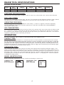
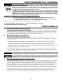
OPERATION
BOSTITCH OFFERS TWO TYPES OF OPERATION FOR THIS SERIES TOOL.
CONT
ACT TRIP:
The common operating procedure on “Contact Trip” tools is for the operator to contact the work to actuate
the trip mechanism while keeping the trigger pulled, thus driving a fastener each time the work is contacted.
This will allow rapid fastener placement on many jobs, such as sheathing, decking and pallet assembly. All
pneumatic tools are subject to recoil when driving fasteners. The tool may bounce, releasing the trip, and if
unintentionally allowed to recontact the work surface with the trigger still actuated (finger still holding trigger
pulled) an unwanted second fastener will be driven.
SEQUENTIAL TRIP:
The Sequential Trip requires the operator to hold the tool against the work before pulling the trigger. This
makes accurate fastener placement easier, for instance on framing, toe nailing and crating applications.The
Sequential Trip allows exact fastener location without the possibility of driving a second fastener on recoil, as
described under “Contact Trip”. The Sequential Trip Tool has a positive safety advantage because it will not
accidentally drive a fastener if the tool is contacted against the work – or anything else – while the operator
is holding the trigger pulled.
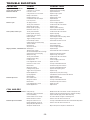
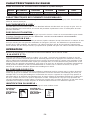
MODEL IDENTIFICATION:
Refer to Operation Instructions on page 7 before proceeding to use this tool.
CONTACT TRIP SEQUENTIAL TRIP
Identified by: Identified by:
BLACK TRIGGER GRAY TRIGGER
MODEL
TOOL
LENGTH HEIGHT WIDTH WEIGHT
ACTUATION
RN45B-1 Contact Trip 10.9” (276.8mm) 10.62” (269.7mm) 4.62” (117.3mm) 6lbs. (2.7kg.)
RN45B-2 Sequential Trip 10.9” (276.8mm) 10.62” (269.7mm) 4.62” (117.3mm) 6lbs. (2.7kg.)

AIR SUPPLY AND CONNECTIONS
Do not use oxygen, combustible gases, or bottled gases as a power source for this tool as
tool may explode, possibly causing injury.
FITTINGS:
Install a male plug on the tool which is free flowing and which will release air pressure from the tool when
disconnected from the supply source.
HOSES:
Air hoses should have a minimum of 150 p.s.i. (10.6 kg/cm2) working pressure rating or 150 percent of the
maximum pressure that could be produced in the air system. The supply hose should contain a fitting that
will provide “quick disconnecting” from the male plug on the tool.
SUPPLY
SOURCE:
Use only clean regulated compressed air as a power source for this tool. NEVER USE OXYGEN, COMBUSTIBLE
GASES, OR BOTTLED GASES, AS A POWER SOURCE FOR THIS TOOLAS TOOLMAY EXPLODE.
REGULATOR:
A pressure regulator with an operating pressure of 0 - 125 p.s.i. (0 - 8.79 KG/CM
2
) is required to control the
operatiing pressure for safe operation of this tool. Do not connect this tool to air pressure which can
potentially exceed 200 p.s.i. (14 KG/CM
2
) as tool may fracture or burst, possibly causing injury.
OPERATING PRESSURE:
Do not exceed recommended maximum operating pressure as tool wear will be greatly increased. The air
supply must be capable of maintaining the operating pressure at the tool. Pressure drops in the air supply
can reduce the tool’s driving power. Refer to “TOOL SPECIFICATIONS” for setting the correct operating
pressure for the tool.
FILTER:
Dirt and water in the air supply are major causes of wear in pneumatic tools. A filter will help to get the best
performance and minimum wear from the tool. The filter must have adequate flow capacity for the specific
installation. The filter has to be kept clean to be effective in providing clean compressed air to the tool.
Consult the manufacturer’s instructions on proper maintenance of your filter. A dirty and clogged filter will
cause a pressure drop which will reduce the tool’s performance.
LUBRICATION
Frequent, but not excessive, lubrication is required for best performance. Oil added through the air line
connection will lubricate the internal parts. Use BOSTITCH Air Tool Lubricant, Mobil Velocite #10, or
equivalent. Do not use detergent oil or additives as these lubricants will cause accelerated wear to the seals
and bumpers in the tool, resulting in poor tool performance and frequent tool maintenance.
If no airline lubricator is used, add oil during use into the air fitting on the tool once or twice a day. Only a few
drops of oil at a time is necessary. Too much oil will only collect inside the tool and will be noticeable in the
exhaust cycle.
COLD WEA
THER OPERATION:
For cold weather operation, near and below freezing, the moisture in the air line may freeze and prevent tool
operation. We recommend the use of BOSTITCH WINTER FORMULA air tool lubricant or permanent
antifreeze (ethylene glycol) as a cold weather lubricant.
CAUTION: Do not store tools in a cold weather environment to prevent frost or ice formation on the
tools operating valves and mechanisms that could cause tool failure.
NOTE:Some commercial air line drying liquids are harmful to “O”-rings and seals – do not use these
low temperature air dryers without checking compatibility.
-5-

LOADING THE RN45B
EYE PROTECTION
which conforms to ANSI specifications and provides protection against
flying particles both from the FRONT and SIDE should ALWAYS be worn by the operator and
others in the work area when connecting to air supply, loading, operating or servicing this
tool. Eye protection is required to guard against flying fasteners and debris, which could
cause severe eye injury.
The employer and/or user must ensure that proper eye protection is worn. Eye protection
equipment must conform to the requirements of the American National Standards Institute,
ANSI Z87.1 and provide both frontal and side protection. NOTE: Non-side shielded
spectacles and face shields alone do not provide adequate protection.
TO PREVENT ACCIDENTAL INJURIES:
•Never place a hand or any other part of the body in nail discharge area of tool while
the air supply is connected.
• Never point the tool at anyone else.
• Never engage in horseplay.
• Never pull the trigger unless nose is directed at the work.
•Always handle the tool with care.
• Do not pull the trigger or depress the trip mechanism while loading the tool.
-6-
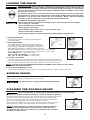
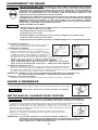
1.Open the magazine:
Pull down door latch and swing door/magazine
cover downward.
2.Check Adjustment:
The nailer must be set for the length of nail to be
used. Nails will not feed smoothly if the magazine
is not correctly adjusted. The magazine contains an
adjustable nail platform on which the nail coil rests.
The nail platform can be moved up and down to three nail settings.
To change setting pull up on the post and twist to the correct step.
1-3/4” (45mm) nails - use bottom step
1-1/4” , 1-1/2” (32, 38mm) - use middle step
3/4”, 7/8”, 1” (19, 22, 25mm) - use top step
3.Load the coil of nails:
Place the coil of nails over the post in the magazine. Uncoil enough nails to
reach the feed pawl. Place the first nail in front of the front tooth on the feed
pawl, in the driver channel. The nail heads must be in the slot in the nose.
NOTE:
Use only nails recommended by Bostitch for RN45B series nailers or nails which
meet the Bostitch specifications.
4.Close the Door/Magazine Cover:
Swing the door/magazine cover closed. Check that the latch pin engages when released.
This gauge can be used to control shingle spacing. Loosen two screws to
adjust gauge to desired shingle exposure, as shown.
Disconnect the air supply before making adjustments.
SHINGLE GAUGE
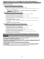
CLEANING THE ROOFING NAILER
Tar and dirt may build up on the nose and trip lever. This can prevent correct
operation. Remove any buildup with kerosene, #2 fuel oil or diesel fuel.
Do not dunk the nailer into these solvents beyond the height of the nail
heads, to avoid getting the solvent into the drive cylinder.
Dry off the nailer before use. Any oil film left after cleanup will accelerate
the tar buildup, and the nailer will require more frequent re-cleaning.
NOTE:
Solvents sprayed on the nose to clean and free up the trip
may have the opposite effect! The solvent may soften the tar on
the shingles and cause tar buildup to be accelerated. Dry operation
is better, as noted above.
Do not use gasoline or similar highly flammable liquids to clean the nailer.
Vapor could be ignited by a spark, causing an explosion.

-7-
TOOL OPERATION
EYE PROTECTION which conforms to ANSI specifications and provides protection against
flying particles both from the FRONT and SIDE should ALWAYS be worn by the operator and
others in the work area when connecting to air supply, loading, operating or servicing this
tool. Eye protection is required to guard against flying fasteners and debris, which could
cause severe eye injury.
The employer and/or user must ensure that proper eye protection is worn. Eye protection
equipment must conform to the requirements of the American National Standards Institute,
ANSI Z87.1 and provide both frontal and side protection. NOTE: Non-side shielded
spectacles and face shields alone do not provide adequate protection.
BEFORE HANDLING OR OPERATING THIS TOOL:
I. READ AND UNDERSTAND THE WARNINGS CONTAINED IN THIS MANUAL.
II. REFER TO “TOOL SPECIFICATIONS” IN THIS MANUAL TO IDENTIFY THE
OPERATING SYSTEM ON YOUR TOOL.
There are three available systems on BOSTITCH pneumatic tools. They are:
1. TRIGGER OPERATION 2. CONTACT TRIP OPERATION 3. SEQUENTIAL TRIP OPERATION
OPERATION
1. TRIGGER OPERATION:
A TRIGGER OPERATED tool requires a single action to drive a fastener. Each time the trigger is pulled
the tool will drive a fastener. The trigger operated model is intended for use only when a contact trip or
sequential trip cannot be used due to the requirements of the application.
2. CONTACT TRIP OPERATION:
The CONTACT TRIP MODEL tool contains a contact trip that operates in conjunction with the trigger to
drive a fastener. There are two methods of operation to drive fasteners with a contact trip tool.
A. SINGLE FASTENER PLACEMENT: To operate the tool in this manner, first position the contact trip
on the work surface, WITHOUT PULLING THE TRIGGER. Depress the contact trip until the nose
touches the work surface and then pull the trigger to drive a fastener. Do not press the tool against
the work with extra force. Instead, allow the tool to recoil off the work surface to avoid a second
unwanted fastener. Remove your finger from the trigger after each operation.
B. RAPID FASTENER OPERATION: To operate the tool in this manner, hold the tool with the contact
trip pointing towards but not touching the work surface. Pull the trigger and then tap the contact trip
against the work surface using a bouncing motion. Each depression of the contact trip will cause a
fastener to be driven.
The operator must not hold the trigger pulled on contact trip tools except during fastening
operation, as serious injury could result if the trip accidentally contacted someone or
something, causing the tool to cycle.
Keep hands and body away from the discharge area of the tool. A contact trip tool may
bounce from the recoil of driving a fastener and an unwanted second fastener may be
driven, possibly causing injury.
3. SEQUENTIAL TRIP OPERATION:
The SEQUENTIAL TRIP MODEL contains a contact trip that operates in conjunction with the trigger to
drive a fastener. To operate a sequential trip tool, first position the contact trip on the work surface
WITHOUT PULLING THE TRIGGER. Depress the contact trip and then pull the trigger to drive a
fastener. As long as the contact trip is contacting the work and is held depressed, the tool will drive a
fastener each time the trigger is depressed. If the contact trip is allowed to leave the work surface, the
sequence described above must be repeated to drive another fastener.

-8-
TOOL OPERATION CHECK:
CAUTION: Remove all fasteners from tool before performing tool operation check.
1. TRIGGER OPERATED TOOL:
A. With finger off the trigger, hold the tool with a firm grip on the handle.
B. Place the nose of the tool against the work surface.
C. Pull the trigger to drive. Release the trigger and cycle is complete.
CAUTION: THE TOOL WILL CYCLE EACH TIME THE TRIGGER IS PULLED!
2. CONTACT TRIP OPERATION:
A. With finger off the trigger, press the contact trip against the work surface.
THE TOOL MUST NOT CYCLE.
B. Hold the tool off the work surface, and pull the trigger.
THE TOOL MUST NOT CYCLE.
C. With the tool off the work surface, pull the trigger. Press the contact trip against the work surface.
THE TOOL MUST CYCLE.
D. Without touching the trigger, press the contact trip against the work surface,
then pull the trigger.
THE TOOL MUST CYCLE.
3. SEQUENTIAL TRIP OPERATION:
A. Press the contact trip against the work surface, without touching the trigger.
THE TOOL MUST NOT CYCLE.
B. Hold the tool off the work surface and pull the trigger.
THE TOOL MUST NOT CYCLE.
Release the trigger. The trigger must return to the trigger stop on the frame.
C. Pull the trigger and press the contact trip against the work surface.
THE TOOL MUST NOT CYCLE.
D. With finger off the trigger, press the contact trip against the work surface. Pull the trigger.
THE TOOL MUST CYCLE.
IN ADDITION TO THE OTHER WARNINGS CONTAINED IN THIS MANUAL
OBSERVE THE FOLLOWING FOR SAFE OPERATION
• Use the BOSTITCH pneumatic tool only for the purpose for which it was designed.
• Never use this tool in a manner that could cause a fastener to be directed toward the user
or others in the work area.
• Do not use the tool as a hammer.
• Always carry the tool by the handle. Never carry the tool by the air hose.
• Do not alter or modify this tool from the original design or function without approval from
BOSTITCH, INC.
• Always be aware that misuse and improper handling of this tool can cause injury to
yourself and others.
• Never clamp or tape the trigger or contact trip in an actuated position.
• Never leave a tool unattended with the air hose attached.
• Do not operate this tool if it does not contain a legible WARNING LABEL.
•Do not continue to use a tool that leaks air or does not function properly. Notify your
nearest BOSTITCH representative if your tool continues to experience functional problems.

-9-
MAINTAINING THE PNEUMATIC TOOL
When working on air tools, note the warnings in this manual and use extra care evaluating
problem tools.
REPLACEMENT PARTS:
BOSTITCH replacement parts are recommended. Do not use modified parts or parts which will not give
equivalent performance to the original equipment.
ASSEMBLY PROCEDURE FOR SEALS:
When repairing a tool, make sure the internal parts are clean and lubricated. Use Parker “O”-LUBE or
equivalent on all “O”-rings. Coat each “O”-ring with “O”-LUBE before assembling. Use a small amount of oil
on all moving surfaces and pivots. After reassembly add a few drops of BOSTITCH Air Tool Lubricant
through the air line fitting before testing.
AIR SUPPLY
-PRESSURE AND VOLUME:
Air volume is as important as air pressure. The air volume supplied to the tool may be inadequate because
of undersize fittings and hoses, or from the effects of dirt and water in the system. Restricted air flow will
prevent the tool from receiving an adequate volume of air, even though the pressure reading is high. The
results will be slow operation, misfeeds or reduced driving power. Before evaluating tool problems for these
symptoms, trace the air supply from the tool to the supply source for restrictive connectors, swivel fittings,
low points containing water and anything else that would prevent full volume flow of air to the tool.

-10-
TROUBLE SHOOTING
PROBLEM CAUSE CORRECTION
Trigger valve housing leaks air O-ring cut or cracked . . . . . . . . . . . . . . . . . . . .Replace O-ring
Trigger valve stem leaks air O-ring/seals cut or cracked . . . . . . . . . . . . . . . .Replace trigger valve assembly
Frame/nose leaks air Loose nose screws . . . . . . . . . . . . . . . . . . . . . .Tighten and recheck
O-ring or Gasket is cut or cracked . . . . . . . . . .Replace O-ring or gasket
Bumper cracked/worn . . . . . . . . . . . . . . . . . . . .Replace bumper
Frame/cap leaks air Damaged gasket or seal . . . . . . . . . . . . . . . . . .Replace gasket or seal
Cracked/worn head valve bumper . . . . . . . . . . .Replace bumper
Loose cap screws . . . . . . . . . . . . . . . . . . . . . .Tighten and recheck
Failure to cycle Air supply restriction . . . . . . . . . . . . . . . . . . . . .Check air supply equipment
Tool dry, lack of lubrication . . . . . . . . . . . . . . . .Use BOSTITCH Air Tool Lubricant
Worn head valve O-rings . . . . . . . . . . . . . . . . .Replace O-rings
Broken cylinder cap spring . . . . . . . . . . . . . . . .Replace cylinder cap spring
Head valve stuck in cap . . . . . . . . . . . . . . . . . .Disassemble/Check/Lubricate
Lack of power; slow to cycle Tool dry, lacks lubrication . . . . . . . . . . . . . . . . .Use BOSTITCH Air Tool Lubricant
Broken cylinder cap spring . . . . . . . . . . . . . . . .Replace cap spring
O-rings/seals cut or cracked . . . . . . . . . . . . . . .Replace O-rings/seals
Exhaust blocked . . . . . . . . . . . . . . . . . . . . . . .Check bumper, head valve spring, muffler
Trigger assembly worn/leaks . . . . . . . . . . . . . .Replace trigger assembly
Dirt/tar build up on driver . . . . . . . . . . . . . . . . .Disassemble nose/driver to clean
Cylinder sleeve not seated correctly
on bottom bumper . . . . . . . . . . . . . . . . . . . . . .Disassemble to correct
Head valve dry . . . . . . . . . . . . . . . . . . . . . . . . .Disassemble/lubricate
Air pressure too low . . . . . . . . . . . . . . . . . . . . .Check air supply equipment
Skipping fasteners; intermittent feed Worn bumper . . . . . . . . . . . . . . . . . . . . . . . . . .Replace bumper
Tar/dirt in driver channel . . . . . . . . . . . . . . . . . .Disassemble and clean nose and driver
Air restriction/inadequate air flow through
quick disconnect socket and plug . . . . . . . . . . .Replace quick disconnect fittings
Worn piston O-ring . . . . . . . . . . . . . . . . . . . . . .Replace O-ring, check driver
Tool dry, lacks lubrication . . . . . . . . . . . . . . . . .Use BOSTITCH Air Tool Lubricant
Damaged pusher spring . . . . . . . . . . . . . . . . . .Replace spring
Low air pressure . . . . . . . . . . . . . . . . . . . . . . . .Check air supply system to tool
Loose magazine nose screws . . . . . . . . . . . . . .Tighten all screws
Fasteners too short for tool . . . . . . . . . . . . . . . .Use only recommended fasteners
Bent fasteners . . . . . . . . . . . . . . . . . . . . . . . . .Discontinue using these fasteners
Wrong size fasteners . . . . . . . . . . . . . . . . . . . .Use only recommended fasteners
Leaking head cap gasket . . . . . . . . . . . . . . . . .Tighten screws/replace gasket
Trigger valve O-ring cut/worn . . . . . . . . . . . . . .Replace O-ring
Broken/chipped driver . . . . . . . . . . . . . . . . . . . .Replace driver (check piston O-ring)
Dry/dirty magazine . . . . . . . . . . . . . . . . . . . . . .Clean/lubricate use BOSTITH Air Tool Lubricant
Worn magazine . . . . . . . . . . . . . . . . . . . . . . . .Replace magazine
Fasteners jam in tool Driver channel worn . . . . . . . . . . . . . . . . . . . . .Replace nose/check door
Wrong size fasteners . . . . . . . . . . . . . . . . . . . .Use only recommended fasteners
Bent fasteners . . . . . . . . . . . . . . . . . . . . . . . . .Discontinue using these fasteners
Loose magazine/nose screws . . . . . . . . . . . . . .Tighten all screws
Broken/chipped driver . . . . . . . . . . . . . . . . . . . .Replace driver
COIL NAILERS
Skipping fasteners; intermittent feed Feed piston dry . . . . . . . . . . . . . . . . . . . . . . . .Add BOSTITCH Air Tool Lubricant in hole in feed piston cover
Feed piston O-rings cracked/worn . . . . . . . . . .Replace O-rings/check bumper and spring. Lubricate assembly.
Check Pawl binding . . . . . . . . . . . . . . . . . . . . .Inspect Pawl and spring on door. Must work freely.
Canister bottom not set correctly . . . . . . . . . . .Set canister bottom for length of nails being used
Broken weld wires in nail coil . . . . . . . . . . . . . .Remove coil of nails and use another coil
Fasteners jam in tool/canister Wrong size fasteners for tool . . . . . . . . . . . . . .Use only recommended fasteners/check canisterbottom adjustment
Broken welded wires in nail coil . . . . . . . . . . . .Remove coil of nails and use another coil
Wrong slide plate adjustment for
wire/plastic collated nail coil . . . . . . . . . . . . . . .Adjust switch pins for wire/plastic collated nail coil

-11-
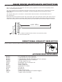
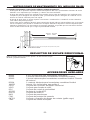
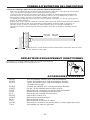
RN45B DRIVER MAINTENANCE INSTRUCTIONS
Worn driver causing poor quality or loss of power:
-Wear on the driving tip will affect the nail drive, giving symptoms of bent and incompletely driven
nails, and damaged nail heads.
-The driver length may be adjusted to allow the driving tip to be redressed to compensate for wear.
Heat and precise measurement are required. Contact a qualified service technician for this
adjustment.
-The length setting for a new driver is shown below. Measurement is from the bottom face of
the main piston.
-Note that the measurement from the top of the piston gives the maximum amount the driver may be
adjusted to allow redressing. Always extend the driver the minimum required to allow redressing to
restore the driving end; several redressings will be possible before this maximum depth is reached.
DIRECTIONAL EXHAUST DEFLECTOR
Loosen screw as shown. Adjust to desired exhaust direction and tighten screw.
ACCESSORIES AVAILABLE
BC601 4 oz. Bostitch Air-Tool Lubricant
BC602 1 pint Bostitch Air-Tool Lubricant
BC603 1 pint Bostitch "Winter-Formula" Air-Tool Lubricant
BC604 1 quart Bostitch Air-Tool Lubricant
100679 O-Ring Lube 1 lb. can
SEQ5 Sequential Trip Conversion Kit
VSA2 Vinyl Siding Kit
DC6 Depth Control Kit
851325 Loctite® 271 Packet
ORK13 O-Ring Kit
BK11 Bumper Kit
FPK1 Frame Protector Kit
CNTK2 Contact Trip Conversion Kit (black trigger)
TVA6 Trigger Valve Assembly
4.675” - 4.685”
(118.7mm - 119.0mm)
5/32” (4.0mm) maximum limit of driver recessed into piston.
Do not exceed this limit.

-12-
INTRODUCCIÓN
La RN45B de Bostitch es una herramienta fabricada con precisión diseñada para trabajos de clavar de alta
velocidad y de gran volumen. Estas herramientas darán un servicio eficiente y seguro, siempre y cuando
sean utilizadas correctamente y con cuidado. Como con cualquier herramienta automática de calidad, el
mejor rendimiento se obtiene siguiendo las indicaciones del fabricante. Por favor, estudie este manual antes
de operar esta herramienta y asegúrese de entender perfectamente las advertencias y precauciones de
seguridad. Las instrucciones sobre instalación, operación y mantenimiento se deben leer cuidadosamente y
el manual deberá conservarse como referencia. NOTA: Se pueden requerir medidas adicionales de
seguridad en relación con la operación particular que usted destina a la herramienta. Póngase en contacto
con su representante o distribuidor de Bostitch en relación con cualquier pregunta o duda relativa a esta
herramienta y su uso. Bostitch, Inc., East Greenwich, Rhode Island 02818.
ÍNDICE
Instrucciones de Seguridad . . . . . . . . . . . . . . . . . . . . . . . . . . . . . . . . . . .13
Especificaciones de la Herramienta;
Consumo de Aire y Presión de Operación . . . . . . . . . . . . . . . . . . . . . . .14
Suministro de Aire: Conexiones, Mangueras, Filtros, Reguladores . . . . . .15
Lubricación y Operación en Época de Frío . . . . . . . . . . . . . . . . . . . . . . . .15
Cómo Cargar la Herramienta . . . . . . . . . . . . . . . . . . . . . . . . . . . . . . . . . .16
Cómo Operar la Herramienta . . . . . . . . . . . . . . . . . . . . . . . . . . . . . . .17, 18
Cómo Mantener la Herramienta Neumática . . . . . . . . . . . . . . . . . . . . . . .19
Localización de Fallas . . . . . . . . . . . . . . . . . . . . . . . . . . . . . . . . . . . . . . .20
Mantenimiento del Impulsor/Cómo Ajustar el Escape . . . . . . . . . . . . . . . .21
NOTA:
Las herramientas de Bostitch han sido fabricadas para proporcionar una excelente satisfacción al cliente y
están diseñadas para lograr el máximo rendimiento al ser utilizadas con sujetadores de precisión de Bostitch
que han sido fabricados a las mismas normas exactas. Bostitch no puede asumir responsabilidad por el
rendimiento de un producto si se utilizan nuestras herramientas con sujetadores o accesorios que no
cumplen con los requisitos específicos establecidos para clavos, grapas y accesorios auténticos de
Bostitch.
GARANTÍA LIMITADA — Sólo EE.UU. y Canadá
A partir del 1 de diciembre de 2005 Bostitch, L.P. garantiza al comprador del comerciante original que el producto
comprado está exento de defectos en material y fabricación, y se compromete a reparar o reemplazar, a opción de
Bostitch, cualquier engrapadora o clavadora neumática defectuosa de marca Bostitch por un período de siete (7) años
desde la fecha de compra (un (1) año de la fecha de compra en el caso de compresores y herramientas utilizadas en
aplicaciones de producción). La garantía no es transferible. Se requiere presentar evidencia de la fecha de compra.
Esta garantía solamente cubre daños resultantes de defectos en material o fabricación, y no cubre condiciones o
desperfectos resultantes del desgaste normal, negligencia, abuso, accidente o reparaciones intentadas o efectuadas
por terceros ajenos a nuestro centro nacional de reparaciones o a los centros de servicio bajo garantía. Las aspas del
impulsor, topes, juntas tóricas, pistones y aros de pistones se consideran componentes de desgaste normal. Para
obtener el rendimiento óptimo de la herramienta Bostitch siempre use fijaciones y piezas de repuesto genuinas de
Bostitch.
ESTA GARANTÍA SUSTITUYE TODA OTRA GARANTÍA, EXPRESA O IMPLÍCITA, INCLUIDAS ENTRE OTRAS,
LAS GARANTÍAS IMPLÍCITAS DE COMERCIABILIDAD O IDONEIDAD PARA UN FIN PARTICULAR. BOSTITCH
NO SERÁ RESPONSABLE DE DAÑOS FORTUITOS O CONSECUENCIALES.
Algunos estados y países no permiten limitaciones a la duración de una garantía implícita ni la exclusión o limitación
de daños fortuitos o consecuenciales, de modo que las limitaciones o exclusiones anteriores pueden no corresponder
a su caso. Esta garantía le concede derechos legales específicos, y usted puede tener también otros derechos que
varían de un estado a otro y de un país a otro.
Para obtener servicio bajo garantía en los EE.UU. devuelva el producto, junto con el comprobante de compra, al
Centro de Servicio bajo Garantía Autorizado Independiente Nacional o Regional de Bostitch en los EE.UU. Dentro de
los EE.UU. usted puede llamarnos al 1-800-556-6696 o visitar www.BOSTITCH.com para ver la ubicación que más
le convenga. En Canadá llámenos al at 800-567-7705 o visite www.BOSTITCH.com.

-13-
INSTRUCCIONES DE SEGURIDAD
Cuando el equipo está conectado al suministro de aire, tanto el operador como todas las personas que
se encuentren en el área de trabajo, SIEMPRE deben usar PROTECCIÓN OCULAR que cumpla las
especificaciones ANSI para resguardo contra partículas volantes arrojadas desde el FRENTE o los
LATERALES. Dicha protección ocular se requiere para proteger contra residuos y remaches volantes,
que podrían causar graves lesiones en los ojos.
El empleador y/o usuario debe asegurar que la debida protección para los ojos sea usada. El equipo
protector de los ojos debe cumplir con los requisitos del Instituto de Normas Nacionales Americano
(American National Standards Institute), ANSI Z87.1 y debe proveer protección de frente y de los lados.
NOTA: Las gafas de seguridad que no están protegidas de los lados y las máscaras por sí solas no
proveen la debida protección.
PRECAUCIÓN:
En algunos entornos será necesaria protección de seguridad adicional. Por ejemplo,
es posible que el área de trabajo incluya la exposición a niveles de ruido que pueden dañar el oído. El
empleador y el usuario deben asegurarse de que cualquier protección necesaria para los oídos sea
provista y utilizada por el operador y demás personas en el área de trabajo. Algunos entornos
requieren el uso de aparatos de protección para la cabeza. Cuando sea necesario, el empleador y el
usuario deben asegurarse de que se utilice protección para la cabeza en conformidad con la norma
ANSI Z89.1.
SUMINISTRO DE AIRE Y CONEXIONES
No utilice oxígeno ni gases combustibles o embotellados como fuente de suministro para esta
herramienta, ya que la herramienta puede estallar, posiblemente causando lesiones.
No utilice fuentes de suministro que potencialmente excedan las 14 Kg/cm
2
(13,8 bars) ya que la
herramienta puede estallar, posiblemente causando lesiones.
El conector de la herramienta no debe tener presión al desconectarse el suministro de aire. Si se
utiliza una conexión equivocada, la herramienta puede permanecer cargada con aire después de
ser desconectada y por lo tanto podrá impulsar un sujetador aún después de que la línea de aire
sea desconectada, posiblemente causando lesiones.
No hale el gatillo ni oprima el brazo de contacto mientras la herramienta esté conectada al
suministro de aire ya que la herramienta puede ciclarse, posiblemente causando lesiones.
Siempre desconecte el suministro de aire: 1.) Antes de efectuar ajustes; 2.) Al hacerle servicio a
la herramienta; 3.) Al despejar un atascamiento; 4.) Cuando la herramienta no esté en uso; 5.) Al
mudarse de un área distinta de trabajo, ya que se puede activar accidentalmente, posiblemente
causando lesiones.
AL CARGAR LA HERRAMIENTA
Al cargar la herramienta: 1.) Nunca coloque una mano o cualquier otra parte del cuerpo en el
área de descarga del sujetador de la herramienta; 2.) Nunca apunte la herramienta hacia otra
persona; 3.) No hale el gatillo ni oprima el disparador ya que se puede activar accidentalmente,
posiblemente causando lesiones.
OPERACIÓN
Siempre maneje la herramienta con cuidado. 1.) Nunca participe en juegos rudos con la
herramienta; 2.) Nunca hale el gatillo al menos que la nariz esté apuntada hacia el trabajo; 3.)
Mantenga a las demás personas a una distancia segura de la herramienta mientras la herramienta
esté en operación ya que se puede activar accidentalmente, causando posibles lesiones.
No mantenga el gatillo halado en las herramientas del brazo de contacto, salvo durante la
operación de engrapado, ya que pueden resultar serias lesiones si el disparador accidentalmente
se pusiera en contacto con alguien o con algo, causando que se cicle la herramienta.
Mantenga las manos y el cuerpo alejados del área de descarga de la herramienta. Una
herramienta con brazo de contacto puede rebotar debido a la reculada al impulsar un sujetador
y se puede impulsar accidentalmente un segundo sujetador, causando posibles lesiones.
Verifique la operación del mecanismo del brazo de contacto frecuentemente. No utilice la herramienta
si el brazo no está funcionando correctamente ya que se puede impulsar accidentalmente otro
sujetador. No interfiera con la debida operación del mecanismo del brazo de contacto.
No meta los sujetadores encima de otros sujetadores o teniendo la herramienta demasiado
inclinada ya que esto podría causar que los sujetadores se desviaran, y a su vez causaran lesiones.
No meta los sujetadores cerca del borde de la pieza de trabajo porque la madera podría
separarse, lo que permitiría que el sujetador se desviara y causara lesiones.
Esta clavadora produce CHISPAS durante la operación. NUNCA use la clavadora cerca de
sustancias, gases ni vapores inflamables, incluidos diluyentes, lacas, pintura, bencina, gasolina,
adhesivos, mástique, pegamentos ni ningún otro material que sea inflamable, combustible o
explosivo -- o vapores, emanaciones o subproductos que puedan serlo. Si se usa la clavadora en
cualquier ambiente de este tipo podría causar una EXPLOSION produciendo lesiones físicas o
fatales para el usuario y las personas en la cercanía.
MANTENIMIENTO DE LA HERRAMIENTA
Tome nota de las advertencias en este manual al trabajar con herramientas neumáticas y tenga
mayor cuidado al evaluar herramientas problemáticas.

-14-
ESPECIFICACIONES DE LA HERRAMIENTA RN45B
Todos las medidas de tornillos y tuercas son métricas.
ESPECIFICACIONES DEL SUJETADOR:
Esta herramienta utiliza de clavos ripias en largos desde 19 - 45mm (3/4" a 1-3/4") y diámetro de espiga de
3,0 mm (0,120")
CONEXIÓN DE AIRE DE LA
HERRAMIENTA:
Esta herramienta usa un enchufe macho de 1/4" N.P.T. El diámetro interior debe ser de 5mm (0,2") o mayor.
La conexión debe ser capaz de descargar la presión de aire de la herramienta cuando es desconectada del
suministro de aire.
PRESIÓN DE OPERACIÓN:
4,9 a 7,1 kg/cm2 (4,8 a 6,9 bars). Seleccione la presión de operación dentro de este rango para el mejor
rendimiento. NO EXCEDA ESTA PRESIÓN DE OPERACIÓN RECOMENDADA.
CONSUMO DE AIRE:
El modelo RN45B requiere 110,41 (3,9 pies cúbicos) por minuto de aire libre para funcionar a razón de 100
sujetadores por minuto, a 80 p.s.i. (5,6 kg/cm2). Utilice la velocidad real a la cual la herramienta se hará
funcionar para determinar la cantidad de aire requerida. Por ejemplo, si su promedio de utilización de
sujetadores es de 50 sujetadores por minuto, usted necesita el 50% de los pies cúbicos por minuto de aire
libre de la herramienta que se requieren una operación a razón de 100 sujetadores por minuto.
OPERACIÓN
BOSTITCH OFRECE DOS TIPOS DE OPERACIÓN PARA HERRAMIENTAS DE ESTA SERIE
DISPARO POR CONTACTO:
El procedimiento de operación común para las herramientas de “Disparo por Contacto” es que el operador
hace contacto con el objeto a ser clavado para activar el mecanismo de disparo, manteniendo halado el
gatillo. Esto hace que se impulse un sujetador cada vez que se hace contacto con el objeto. Esto permite la
rápida colocación de sujetadores en muchos trabajos, tales como entablado, pisos, y el ensamble de
paletas. Toas las herramientas neumáticas están sujetas a la reculada al impulsar sujetadores. La
herramienta puede rebotar, soltando el disparo, y si se le permite inintencionalmente encontrar en contacto
nuevamente con la superficie de trabajo mientras el gatillo está todavía activado (mientras el dedo mantiene
el gatillo halado), se impulsará un segundo sujetador indeseado.
DISPARO SECUENCIAL:
El Disparo Secuencial requiere que el operador mantenga la herramienta sobre la superficie del objeto antes
de halar el gatillo. Esto permite la precisa y fácil colocación de sujetadores en muchos trabajos, por ejemplo,
en aplicaciones de construcción de marcos, con clavos oblicuos y la construcción de cajones de construcción.
El Disparo Secuencial permite la colocación exacta de sujetadores sin la posibilidad de impulsar un segundo
sujetador en la reculada, según se describe bajo “Disparo por Contacto”.La Herramienta de Disparo
Secuencial tiene una ventaja de seguridad positiva, ya que no impulsará un sujetador accidentalmente si la
herramienta entra en contacto con el objeto de trabajo – o cualquier otra cosa – mientras el operador man
tenga el gatillo halado.
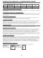
IDENTIFICACIÓN DE MODELO:
Consulte las Instrucciones de Operación en la página 17 antes de usar esta herramienta.
OPERACIÓN POR DISPARO
CONTACTO SECUENCIAL
Identificada por: identificado por:
GATILLO NEGRO GATILLO GRIS
ACTIVACIÓN DE
MODELO HERRAMIENTA LARGO ALTURA ANCHO PESO
RN45B-1 Disparo por Contacto 27,25 cm (10,9") 26,5 cm (10,6") 11,5 cm (4,6") 2,7 kg (5,96 libras)
RN45B-2 Disparo Secuencial 27,25 cm (10,9") 26,5 cm (10,6") 11,5 cm (4,6") 2,7 kg (5,96 libras)

SUMINISTRO DE AIRE Y CONEXIONES
No use oxígeno, gases combustibles o gases embotellados como una fuente de suministro
para esta herramienta, ya que la herramienta puede estallar, posiblemente causando lesiones.
CONEXIONES:
Instale un enchufe macho en la herramienta que fluya libre y que descargue la presión de aire de la
herramienta cuando sea desconectada de la fuente de suministro.
MANGUERAS:
Las mangueras de aire deben tener un mínimo de clasificación de presión de operación de 10,5 Kg/cm
2
(10,3 bars) ó 150 porciento de la presión máxima de operación que podría producirse en el sistema de aire.
La manguera de suministro debe contener una conexión que provea un “desconectado rápido” del enchufe
macho en la herramienta.
FUENTE DE SUMINISTRO:
Use sólo aire comprimido regulado limpio como una fuente de suministro para esta herramienta. NUNCA
USE OXÍGENO, GASES COMBUSTIBLES O GASES EMBOTELLADOS COMO UNA FUENTE DE
SUMINISTRO PARA ESTA HERRAMIENTA, YA QUE LA HERRAMIENTA PODRÍA ESTALLAR.
REGULADOR:
Se requiere un regulador de presión con una presión de operación de 0-8,7 Kg/cm
2
(8,6 bars) para controlar
la presión de operación para la segura operación de esta herramienta. No conecte esta herramienta a una
presión de aire que potencialmente exceda 14 Kg/cm
2
(13,8 bars), ya que la herramienta puede fracturarse o
estallar, posiblemente causando lesiones.
PRESIÓN DE OPERACIÓN:
No exceda una presión de operación de 7,0 Kg/cm2 (6,9 bars) El suministro de aire debe ser capaz de
mantener la presión de operación en la herramienta. Las caídas de presión en el suministro de aire pueden
reducir la potencia de impulso de la herramienta. Consulte “ESPECIFICACIONES DE LA HERRAMIENTA”
para fijar la debida presión de operación para la herramienta.
FIL
TRO:
La suciedad y el agua en el suministro de aire son causas principales del desgaste en las herramientas
neumáticas. Un filtro puede ayudar a obtener el mejor rendimiento y el desgaste mínimo de la herramienta.
El filtro debe tener una capacidad de flujo adecuada para la instalación en particular. El filtro debe ser
mantenido limpio para que sea eficaz en proveer aire comprimido limpio a la herramienta. Consulte las
instrucciones del fabricante para el debido mantenimiento de su filtro. Un filtro sucio y atascado causará una
caída de presión que reducirá el rendimiento de la herramienta.
LUBRICACIÓN
Para el mejor rendimiento se requiere una lubricación frecuente pero no excesiva. El aceite añadido a través
de la conexión de la línea de aire lubricará las piezas internas. Use el Lubricante de Herramientas de Aire
Mobil Velocite #10 de BOSTITCH o un equivalente. No use aceite detergente o aditivos, ya que estos
lubricantes causan el desgaste acelerado de los sellos y los amortiguadores de choque en la herramienta,
dando como resultado un mal rendimiento de la herramienta y el mantenimiento frecuente de la misma.
Si no se usa un lubricante de línea de aire, añada aceite cuando se esté usando en la conexión de aire en la
herramienta una o dos veces al día. Basta con añadir unas cuantas gotas cada vez. Si añade demasiado
aceite, se acumulará dentro de la herramienta y se notará en el ciclo de escape.
OPERACIÓN EN LA ÉPOCA DE FRÍO:
Para la operación en la época de frío, cerca o bajo de la temperatura de congelación, la humedad en la línea
de aire puede congelarse e impedir que la herramienta funcione. Recomendamos el uso del lubricante de
herramientas de aire BOSTITCH WINTER FORMULA o un anti-descongelante permanente (glicol de etileno)
como un lubricante para la época de frío.
NOTA: No almacene las herramientas en ambientes fríos para impedir que se forme el hielo en
las válvulas y los mecanismos de operación de la herramienta, lo cual podría hacer que la
herramienta falle.
NOTA: Algunos líquidos comerciales secadores de líneas de aire pueden dañar los anillos en “O”
y los sellos — no use estos secadores de aire de baja temperatura sin verificar su
compatibilidad.
-15-

-16-
CÓMO CARGAR EL RN45B
Cuando el equipo está conectado al suministro de aire, tanto el operador como todas las
personas que se encuentren en el área de trabajo, SIEMPRE deben usar PROTECCIÓN OCULAR
que cumpla las especificaciones ANSI para resguardo contra partículas volantes arrojadas
desde el FRENTE o los LATERALES. Dicha protección ocular se requiere para proteger contra
residuos y remaches volantes, que podrían causar graves lesiones en los ojos.
El empleador y/o usuario debe asegurar que la debida protección para los ojos sea usada.
El equipo protector de los ojos debe cumplir con los requisitos del Instituto de Normas
Nacionales Americano (American National Standards Institute), ANSI Z87.1 y debe proveer
protección de frente y de los lados. NOTA: Las gafas de seguridad que no están protegidas
de los lados y las máscaras por sí solas no proveen la debida protección.
ADVERTENCIA: PARA IMPEDIR LESIONES ACCIDENTALES:
• Nunca coloque una mano o cualquier otra parte del cuerpo en el área de descarga del
sujetador de la herramienta mientras el suministro de aire está conectado;
• Nunca apunte la herramienta hacia otra persona;
• Nunca participe en juegos rudos con la herramienta;
• Nunca hale el gatillo a menos que la nariz esté apuntada hacia el trabajo;
• Siempre maneje la herramienta con cuidado.
• No hale el gatillo ni oprima el mecanismo de disparo al cargar la herramienta.
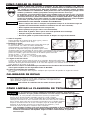
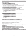
1. Abra el cargador:
Hale el pestillo de la puerta hacia abajo y gire y abra la
puerta/tapa del cargador hacia abajo.
2. Verifique el ajuste:
La clavadora debe ser ajustada para el largo del clavo que
se está usando. Los clavos no serán alimentados
uniformemente si el cargador no está debidamente
ajustado. El cargador incluye una plataforma para clavos
ajustable sobre la cual la bobina de clavos reposa. La plataforma de clavos puede
movers hacia arriba y hacia abajo a tres ajustes. Para cambiar el ajuste, hale el
poste hacia arriba y gire hasta colocarlo en el debido ajuste clavos de
45 mm (1-3/4") — use el ajuste inferior
32, 38 mm (1-1/4", 1-1/2") — use el ajuste del medio
19, 22, 25 mm (3/4", 7/8", 1") — use el ajuste superior
3. Cargue el rollo de clavos:
Coloque el rollo de clavos sobre el poste en el cargador. Desenrolle suficientes
clavos como para alcanzar el trinquete de alimentación. Coloque el primer clavo en frente del diente
delantero del trinquete de alimentación en el canal del impulsor. Las cabezas de los clavos deben
estar dentro de la ranura en la nariz.
NOTA: Use sólo clavos recomendados por Bostitch en las clavadoras de la serie RN45B o
clavos que cumplan con las especificaciones de Bostitch.
4) Cierre la Puerta/Tapa del Cargador:
Gire y cierre la puerta/tapa del cargador. Verifique que el pasador del pestillo se enganche cuando
se suelte.
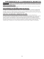
Este calibrador puede ser usado para controlar la separación entre las
ripias. Afloje dos tornillos para ajustar el calibrador a la exposición de
ripias deseada, según se muestra
Desconecte el suministro de aire antes de hacer ajustes.
CALIBRADOR DE RIPIAS
CÓMO LIMPIAR LA CLAVADORA DE TECHADO
El alquitrán y el sucio pueden acumularse en la nariz y la palanca de
disparo. Esto puede impedir la debida operación. Quite cualquier
acumulación con kerosén, aceite combustible #2 o combustible diesel. No
sumerja la clavadora en estos solventes más allá de la altura de las cabezas
de los clavos para evitar que el solvente se introduzca en el cilindro impulsor.
Seque la clavadora antes de usarla. Cualquier capa de aceite que quede
después de la limpieza acelerará la acumulación de alquitrán, y será
necesario volver a limpiar la clavadora más a menudo.
NOTA: ¡Los solventes rociados en la nariz para limpiar y destrabar el disparo pueden tener el
efecto contrario! El solvente puede suavizar el alquitrán en las ripias y causar que se
acelere la acumulación del alquitrán. Según se indicó anteriormente, la operación
seca es mejor.
No use gasolina o líquidos altamente inflamables similares para limpiar la
clavadora. El vapor puede encenderse con una chispa, causando una explosión.

OPERACIÓN DE LA HERRAMIENTA
Cuando el equipo está conectado al suministro de aire, tanto el operador como todas las
personas que se encuentren en el área de trabajo, SIEMPRE deben usar PROTECCIÓN
OCULAR que cumpla las especificaciones ANSI para resguardo contra partículas volantes
arrojadas desde el FRENTE o los LATERALES. Dicha protección ocular se requiere para
proteger contra residuos y remaches volantes, que podrían causar graves lesiones en los ojos.
El empleador y/o usuario debe asegurar que la debida protección para los ojos sea usada.
El equipo protector de los ojos debe cumplir con los requisitos del Instituto de Normas
Nacionales Americano (American National Standards Institute), ANSI Z87.1 y debe proveer
protección de frente y de los lados. NOTA: Las gafas de seguridad que no están protegidas
de los lados y las máscaras por sí solas no proveen la debida protección.
ANTES DE MANEJAR U OPERAR ESTA
HERRAMIENTA:
I. LEA Y ENTIENDA LAS ADVERTENCIAS CONTENIDAS EN ESTE MANUAL.
II. CONSULTE “ESPECIFICACIONES DE LA HERRAMIENTA” EN ESTE MANUAL PARA
IDENTIFICAR EL SISTEMA OPERATIVO DE SU HERRAMIENTA.
Se dispone de tres sistemas operativos para las herramientas neumáticas de BOSTITCH. Éstos son:
1. OPERACIÓN POR GATILLO 2. OPERACIÓN DE DISPARO POR CONTACTO
3. OPERACIÓN DE DISPARO SECUENCIAL
OPERACIÓN
1. OPERACIÓN POR GATILLO:
Una herramienta OPERADA POR GATILLO requiere una sola acción para impulsar al sujetador. Cada
vez que se hala el gatillo la herramienta impulsará un sujetador. El modelo operado por gatillo está
destinado a ser usado sólo cuando el disparo por contacto o el disparo secuencial no puede usarse
debido a los requisitos de la aplicación.
2. OPERACIÓN DE DISPARO POR CONTACTO:
La herramienta de MODELO DE DISPARO POR CONTACTO incluye un disparador por contacto del
objeto que está siendo clavado que opera junto con el gatillo para impulsar un sujetador. Existen dos
métodos de operación para impulsar los sujetadores con una herramienta de disparo por contacto.
A. COLOCACIÓN DE UN SOLO SUJETADOR: Para operar la herramienta de esta forma, primero
coloque el disparo por contacto en la superficie del objeto SIN HALAR EL GATILLO. Oprima el
disparo por contacto hasta que la nariz toque la superficie del objeto y luego hale el gatillo para
impulsar un sujetador. No presione la herramienta contra la superficie del objeto a clavar usando
fuerza extra. En vez de eso, permita que la herramienta recule de la superficie del objeto para evitar
un segundo sujetador indeseado. Quite el dedo del gatillo después de cada operación.
B. OPERACIÓN RÁPIDA DE SUJETADOR: Para operar la herramienta de esta forma, hale el gatillo
con la herramienta separada del objeto a ser clavado. Para impulsar los sujetadores, golpee
ligeramente la nariz de la herramienta sobre la superficie del objeto aplicando un movimiento de
rebote. Cada vez que oprima el disparador por contacto, se impulsará un sujetador.
El operador no debe sostener el gatillo halado en las herramientas de disparo por contacto,
salvo durante la operación de engrapado, ya que pueden resultar serias lesiones si el
disparador accidentalmente se pusiera en contacto con alguien o con algo, causando que
se cicle la herramienta.
Mantenga las manos y el cuerpo alejados del área de descarga de la herramienta. Una
herramienta de disparo por contacto puede rebotar debido a la reculada al impulsar un
sujetador y se puede impulsar accidentalmente un segundo sujetador, causando
posibles lesiones.
3. OPERACIÓN DE DISPARO SECUENCIAL:
El MODELO DE OPERACIÓN SECUENCIAL incluye un disparador por contacto del objeto que funciona
junto con el gatillo para impulsar un sujetador. Para operar una herramienta de disparo secuencial, primero
coloque el disparo por contacto en la superficie del objeto SIN HALAR EL GATILLO. Oprima el disparo por
contacto y luego hale el gatillo para impulsar un sujetador. Mientras el disparo por contacto esté en
contacto con el objeto y se mantiene oprimido, la herramienta impulsará un sujetador cada vez que se
oprima el gatillo. Si se permite que el disparo por contacto deje la superficie del objeto, la secuencia
descrita anteriormente tendrá que ser repetida para impulsar otro sujetador.
El Modelo de Disparo Secuencial provee una ventaja positiva de seguridad ya que no impulsará
accidentalmente un sujetador si se permite que la nariz de la herramienta accidentalmente entre en
contacto con la superficie del objeto — u otra cosa — mientras el dedo mantiene halado el gatillo.
-17-

-18-
VERIFICACIÓN DE LA OPERACIÓN DE LA HERRAMIENTA:
¡PRECAUCIÓN: Quite todos los sujetadores de la herramienta antes de efectuar la verificaciÓn de la
operaciÓn de la herramienta!
1. HERRAMIENTA OPERADA
POR GATILLO:
A. Con el dedo alejado del gatillo, sostenga la herramienta tomándola firmemente por la manija.
B. Coloque la nariz de la herramienta contra la superficie del trabajo.
C. Hale del gatillo para impulsar. Suelte el gatillo para completar el ciclo.
¡PRECAUCIÓN: SE ACTIVARÁ LA HERRAMIENTA CADA VEZ QUE SE HALE EL GATILLO!
2. OPERACIÓN DE DISPARO POR CONTACTO:
A. Apriete el disparador de contacto contra la superficie de trabajo, sin tocar el gatillo.
LA HERRAMIENTA NO DEBE EFECTUAR SU CICLO.
B. Sostenga la herramienta alejada de la superficie de trabajo, y hale el gatillo.
LA HERRAMIENTA NO DEBE EFECTUAR SU CICLO.
C. Con la herramienta alejada de la superficie de trabajo, hale el gatillo y apriete el disparador de
contacto contra la superficie de trabajo.
LA HERRAMIENTA SÍ DEBE EFECTUAR SU CICLO.
D. Con el dedo alejado del gatillo, apriete el disparador de contacto contra la superficie de trabajo.
Hale el gatillo.
LA HERRAMIENTA SÍ DEBE EFECTUAR SU CICLO.
3. OPERACIÓN POR DISPARO SECUENCIAL:
A. Presione el disparador de contacto contra la superficie de trabajo, sin tocar el gatillo.
LA HERRAMIENTA NO DEBE EFECTUAR SU CICLO.
B. Sostenga la herramienta alejada de la superficie de trabajo, y hale el gatillo.
LA HERRAMIENTA NO DEBE EFECTUAR SU CICLO.
C. Hale el gatillo y presione el disparador de contacto contra la superficie de trabajo.
LA HERRAMIENTA NO DEBE EFECTUAR SU CICLO.
D. Con el dedo alejado del gatillo, presione el disparador de contacto contra la superficie de trabajo.
Hale el gatillo.
LA HERRAMIENTA SÍ DEBE EFECTUAR SU CICLO.
ADEMÁS DE LAS OTRAS ADVERTENCIAS CONTENIDAS EN ESTE
MANUAL, OBSERVE LO SIGUIENTE PARA UNA OPERACIÓN SEGURA.
• Utilice la herramienta neumática de BOSTITCH únicamente para impulsar sujetadores.
• Jamás utilice esta herramienta de manera que pudiera causar que un sujetador sea
dirigido hacia usted mismo u otras personas dentro del área de trabajo.
• No utilice la herramienta como un martillo.
• Siempre cargue la herramienta por la manija. Jamás cargue la herramienta por la manguera de aire.
• No modifique o altere esta herramienta de su diseño original o función sin la aprobación
de BOSTITCH, INC.
• Siempre esté consciente de que el mal trato y manejo inadecuado de esta herramienta
puede originar lesiones para usted y los demás.
• Jamás sujete o ate con cinta el gatillo o el disparador de contacto en una posición activada.
• Jamás deje una herramienta sola con la manguera de aire conectada.
• NOTA: No siga usando una herramienta que tenga una fuga de aire o que no funciona debidamente.
Notifique a su representante de BOSTITCH más cercano si su herramienta sigue teniendo
problemas de funcionamiento.

-19-
MANTENIMIENTO DE LA HERRAMIENTA NEUMÁTICA
Al trabajar con herramientas neumáticas, tenga presente las advertencias que se hacen
en este manual, y sea particularmente cuidadoso al evaluar herramientas problemáticas.
PARTES DE REEMPLAZO:
Se recomienda partes de reemplazo de BOSTITCH. No utilice partes modificadas ni partes que no brinden
el mismo rendimiento que el equipo original.
PROCEDIMIENTO DE ENSAMBLE PARA LOS SELLOS:
Al reparar una herramienta, asegúrese de que las partes internas estén limpias y lubricadas. Utilice Parker
“O” -LUBE o su equivalente en todos los anillos en “O” . Cubra cada anillo en “O” con “O” -LUBE antes de
ensamblar. Utilice una cantidad pequeña de aceite en todas las superficies y pivotes móviles. Después del
rearmado, añada unas cuantas gotas del Lubricante para Herramientas Neumáticas de BOSTITCH mediante
la conexión de la línea de aire, antes de probar la herramienta.
PRESIÓN Y
VOLUMEN DEL SUMINISTRO DE AIRE:
El volumen de aire es tan importante como la presión del aire. El volumen de aire suministrado a la
herramienta puede ser inadecuado debido a conexiones y mangueras más pequeñas que lo normal, o debido
a los efectos de polvo y agua dentro del sistema. Un flujo de aire restringido impedirá que la herramienta
reciba un volumen de aire adecuado, aunque la lectura de la presión sea alta. Los resultados serán una
operación lenta, la mala alimentación o una potencia impulsadora reducida. Antes de evaluar los problemas
de la herramienta en busca de estos síntomas, siga la pista del suministro de aire desde la herramienta hasta
la fuente de suministro para ver si hay conexiones restrictivas, accesorios giratorios, puntos bajos que
contienen agua y cualquier otra cosa que evitaría un flujo de aire de volumen completo a la herramienta.

-20-
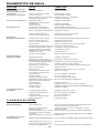
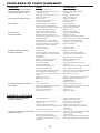
DIAGNÓSTICO DE FALLA
PROBLEMA CAUSA CORRECCIÓN
Fuga de aire en la envoltura de la
válvula disparadora. Anillo en O cortado o rajado . . . . . . . . . . . . . . .Reemplazar el anillo en O.
Vástago de la válvula disparadora
tiene fuga de aire.Anillos en O/sellos cortados o rajados. . . . . . . .Reemplazar anillo en O/sellos.
Fuga de aire en el armazón/nariz. Tornillos de nariz flojos. . . . . . . . . . . . . . . . . . .Apriete y verifique nuevamente.
Anillo en O/empaquetadura cortada o rajada . .Reemplazar el anillo en O o empaquetadura
Amortiguador rajado/desgastado. . . . . . . . . . . .Reemplazar el amortiguador.
Fuga de aire en el armazón/tapón. Empaquetadura rajada. . . . . . . . . . . . . . . . . . .Reemplazar la empaquetadura.
Amortiguador de la válvula de cabeza
rajado/desgastado. . . . . . . . . . . . . . . . . . . . . . .Reemplazar el amortiguador.
Tornillos de tapa flojos. . . . . . . . . . . . . . . . . . . .Apriete y verifique nuevamente.
No desempeña su ciclo. Restricción en el suministro de aire. . . . . . . . . .Verifique el equipo de suministro de aire.
Herramienta seca, falta de lubricación. . . . . . . .Utilice el Lubricante para Herramientas Neumáticas de BOSTITCH.
Anillos en O de la válvula de cabeza desgastados .Reemplazar los anillos en O.
Resorte de la tapa del cilindro roto. . . . . . . . . .Reemplazar el resorte de la tapa del cilindro
Válvula de cabeza atorada en el tapón. . . . . . .Desensamblar/Verificar/Lubricar.
Falta de potencia
Desempeña su ciclo lentamente Herramienta seca, necesita lubricación. . . . . . .Utilice el Lubricante para Herramientas Neumáticas de BOSTITCH.
Resorte de la tapa del cilindro roto. . . . . . . . . .Reemplazar el resorte de la tapa.
Anillos en O/sellos cortados o rajados. . . . . . . .Reemplazar los anillos en O/sellos.
Escape bloqueado . . . . . . . . . . . . . . . . . . . . . .Verificar el amortiguador, resorte de la válvula de cabeza.
Ensamblaje del gatillo desgastado/tiene fugas. .Reemplazar el ensamblaje del gatillo.
Acumulación de polvo/alquitrán en impulsor. . . .Desensamblar la nariz/impulsor para limpiar
La manga del cilindro no está asentada . . . . . .Desensamblar para corregir.
debidamente en el amortiguador de abajo.
Válvula de cabeza seca. . . . . . . . . . . . . . . . . . .Desensamblar/lubricar.
Presión de aire demasiado baja. . . . . . . . . . . . .Verifique el equipo de suministro de aire
Sujetadores que saltan,
alimentación intermitente Amortiguador desgastado . . . . . . . . . . . . . . . . .Reemplazar el amortiguador.
Alquitrán/polvo en el canal del impulsor . . . . . .Desensamblar y limpiar la nariz y el impulsor
Restricción de aire/flujo de aire inadecuado a través
del casquillo y tapón de desconectado rápido . . . .Reemplazar los accesorios de desconectado rápido.
Anillo en O de pistón desgastado . . . . . . . . . . .Reemplazar el anillo en O, verificar el impulsor
Herramienta seca, necesita lubricación . . . . . . .Utilice el Lubricante para Herramientas Neumáticas de BOSTITCH.
Resorte de empuje dañado . . . . . . . . . . . . . . .Reemplazar el resorte.
Baja presión de aire . . . . . . . . . . . . . . . . . . . . .Verifique el sistema de suministro de aire a la herramienta.
Tornillos flojos en la nariz del cargador . . . . . . .Apriete todos los tornillos.
Los sujetadores son demasiado cortos
para la herramienta. . . . . . . . . . . . . . . . . . . . . .Use sólo los sujetadores recomendados.
Sujetadores doblados. . . . . . . . . . . . . . . . . . . .No use estos sujetadores más.
Sujetadores de tamaño equivocado. . . . . . . . . .Use sólo los sujetadores recomendados.
Empaquetadura de la tapa de cabeza con fugas . .Apriete los tornillos/Reemplazar la empaquetadura.
Anillo en O de la válvula del disparador
cortado/desgastado . . . . . . . . . . . . . . . . . . . . .Reemplazar el anillo en O.
Impulsor roto/quebrado. . . . . . . . . . . . . . . . . . .Reemplazar el impulsor. (Verificar el anillo en O del pistón).
Cargador seco/sucio. . . . . . . . . . . . . . . . . . . . .Limpiar/Lubricar. Utilice Lubricante para Herramientas Neumáticas de BOSTITCH.
Cargador desgastado. . . . . . . . . . . . . . . . . . . .Reemplazar el cargador.
Los sujetadores se atoran en
la herramienta Canal del impulsador desgastado. . . . . . . . . . .Reemplazar la nariz/Verificar la puerta.
Sujetadores de tamaño equivocado. . . . . . . . . .Use sólo los sujetadores recomendados
Sujetadores doblados. . . . . . . . . . . . . . . . . . . .No use estos sujetadores más.
Tornillos flojos en el cargador/la nariz. . . . . . . .Apriete todos los tornillos.
Impulsor roto/quebrado. . . . . . . . . . . . . . . . . . .Reemplazar el impulsor.
CLAVADORAS DE BOBINA
Sujetadores que saltan
Alimentación intermitente Pistón alimentador seco. . . . . . . . . . . . . . . . . .Agregue el Lubricante para Herramientas Neumáticas de BOSTITCH
en el orificio de la tapa del pistón alimentador
Anillos en O del pistón alimentador . . . . . . . . .Reemplazar los anillos en O/Verificar el amortiguador y el resorte.
quebrados/desgastados Lubricar el ensamblaje
Inspeccione el trinquete para ver si se atasca . .Revise el trinquete y el resorte de la puerta. Deben funcionar libremente.
Parte inferior del cargador no está fijada
correctamente . . . . . . . . . . . . . . . . . . . . . . . . .Ajuste la parte inferior del cargador para el largo de clavos que se está utilizando
Alambres de soldadura rotos en rollo del clavo . . .Discontinúe su uso.
Los sujetadores se atoran en la
herramienta/cargador. Sujetadores de tamaño equivocado parala herramienta .Use sólo los sujetadores recomendados. Verifique el ajuste del fondo del cargador.
Alambres soldados rotos en rollo del clavo . . . .Discontinúe su uso.
Ajuste equivocado de placa deslizante para
rollo de clavos de alambre/plástico . . . . . . . . . .Ajuste las clavijas del ajustador para el rollode clavos de alambre/plástico.
La page est en cours de chargement...
La page est en cours de chargement...
La page est en cours de chargement...
La page est en cours de chargement...
La page est en cours de chargement...
La page est en cours de chargement...
La page est en cours de chargement...
La page est en cours de chargement...
La page est en cours de chargement...
La page est en cours de chargement...
La page est en cours de chargement...
La page est en cours de chargement...
-
 1
1
-
 2
2
-
 3
3
-
 4
4
-
 5
5
-
 6
6
-
 7
7
-
 8
8
-
 9
9
-
 10
10
-
 11
11
-
 12
12
-
 13
13
-
 14
14
-
 15
15
-
 16
16
-
 17
17
-
 18
18
-
 19
19
-
 20
20
-
 21
21
-
 22
22
-
 23
23
-
 24
24
-
 25
25
-
 26
26
-
 27
27
-
 28
28
-
 29
29
-
 30
30
-
 31
31
-
 32
32


Bostitch Nail Gun RN45B Manuel utilisateur
- Catégorie
- Cloueuse
- Taper
- Manuel utilisateur
- Ce manuel convient également à
dans d''autres langues
- English: Bostitch Nail Gun RN45B User manual
- español: Bostitch Nail Gun RN45B Manual de usuario
Documents connexes
-
Bostitch LPF21PL Manuel utilisateur
-
Bostitch F33PT Manuel utilisateur
-
-
Bostitch DA1564K Manuel utilisateur
-
-
-
-
Bostitch MIII812CNCT Manuel utilisateur
-
-
