
Savant Product Regulatory Statement | 009-1950-02
220127 | © 2022 Savant Systems, Inc.
45 Perseverance Way, Hyannis, MA 02601
Savant.com | 508.683.2500
1 of 2
Important Safety Information - Read First!
Before installing, configuring, or operating any equipment, all relevant technical documentation must be read,
understood, and followed. Savant technical documentation may contain important product-specific installation,
mounting, and safety instructions, and can be accessed through the Savant Store.
Scan the QR code or visit the URL below, enter the relevant product name or SKU in the Search Savant prompt, and
select the product purchased to find documents, specifications and more.
https://store.savant.com/DefaultStore/ccrz__HomePage
Product Information and Regulatory Statement
Safety Statements
All safety instructions below must be read, understood, and
carefully followed under all applicable circumstances when
working with any Savant equipment.
1. Follow all input power ratings marked on product near power
input!
2. If fuse replacement is required, replacement fuse should match
fuse rating marked on the product.
3. Do not use equipment near water.
4. Clean only with dry cloth.
5. Do not block any ventilation openings or install near any heat
sources such as heat registers, stoves, radiators, amplifiers,
etc.
6. Refer all servicing to qualified service personnel. Servicing is
required when any part of the apparatus has been damaged in
any way, or fails to operate normally for any reason.
7. Use only attachments/accessories specified by the
manufacturer, following all relevant safety precautions for any
such attachments/accessories.
8. For applicable equipment, use the included power cord with
the grounding prong intact to insure proper grounding of the
device.
9. If the provided plug does not fit the desired outlet, contact a
licensed electrician to replace the obsolete outlet.
10. Protect any power cord from being walked on, pinched,
strained, or otherwise potentially damaged, especially at the
outlet or device connections.
11. Disconnect any outlet powered apparatus from its power
source during lightning storms or when unused for long
periods of time.
12. To completely disconnect equipment from AC mains power,
disconnect the power supply cord plug from the AC
receptacle on the device.
13. For any hardwired or fixed in-wall apparatus, carefully follow
all wiring diagrams and instructions. All electrical wiring
and servicing should be performed by a properly licensed
electrician.
Déclarations de Sécurité
Toutes les instructions de sécurité ci-dessous doivent être lues,
comprises et soigneusement suivies dans toutes les circonstances
applicables lorsque vous travaillez avec un équipement Savant.
1. Suivez toutes les puissances nominales indiquées sur le
produit près de la puissance absorbée!
2. Si le remplacement du fusible est nécessaire, le fusible de
remplacement doit correspondre à la valeur nominale du
fusible indiquée sur le produit.
3. N’utilisez pas d’équipement près de l’eau.
4. Nettoyer uniquement avec un chion sec.
5. Ne bloquez pas les ouvertures de ventilation et n’installez pas
à proximité de sources de chaleur telles que les registres de
chaleur, les cuisinières, les radiateurs, les amplificateurs, etc.
6. Confiez toutes les réparations à un technicien qualifié.
Un entretien est requis lorsqu’une partie de l’appareil a
été endommagée de quelque manière que ce soit ou ne
fonctionne pas normalement pour une raison quelconque.
7. Utilisez uniquement les attachements / accessoires spécifiés
par le fabricant, en suivant toutes les précautions de sécurité
applicables à ces attachements / accessoires.
8. Pour l’équipement applicable, utilisez le cordon d’alimentation
inclus avec la broche de mise à la terre intacte pour assurer
une mise à la terre correcte de l’appareil.
9. Si la fiche fournie ne correspond pas à la prise souhaitée,
contactez un électricien agréé pour remplacer la prise
obsolète.
10. Protégez tout cordon d’alimentation contre les piétinements,
les pincements, les tensions ou autres dommages potentiels,
en particulier au niveau de la prise ou des connexions de
l’appareil.
11. Débranchez tout appareil alimenté par une prise de courant de
sa source d’alimentation pendant les orages ou lorsqu’il n’est
pas utilisé pendant de longues périodes.
12. Pour déconnecter complètement l’équipement du secteur,
débranchez la fiche du cordon d’alimentation de la prise
secteur de l’appareil.
13. Pour tout appareil encastré ou câblé, suivez attentivement
tous les schémas de câblage et les instructions. Tout le
câblage électrique et l’entretien doivent être eectués par un
électricien dûment agréé.
IMPORTANT NOTES:
• For product mounting, installation, safety instructions, technical specifications, and more, refer to the product Quick
Reference Guide, available via the link or QR code noted above.
• For regulatory and compliance information, see reverse of this sheet and/or product packaging.

Savant Product Regulatory Statement | 009-1950-02
220127 | © 2022 Savant Systems, Inc.
45 Perseverance Way, Hyannis, MA 02601
Savant.com | 508.683.2500
2 of 2
FCC Regulations
This device complies with part 15 of the FCC Rules. Operation is subject to the following two conditions:
1. This device may not cause harmful interference, and
2. This device must accept any interference received, including interference that may cause undesired operation.
This equipment has been tested and found to comply with the limits for CLASS B digital devices, pursuant to Part 15 of FCC Rules.
These limits are designed to provide reasonable protection against harmful interference when the equipment is operated in a residential
installation. This equipment generates, uses and can radiate radio frequency energy and, if not installed and used in accordance with
the instructions, may cause harmful interference to radio communications. If this equipment does cause harmful interference to radio
or television reception, which can be determined by turning the equipment o and on, the user is encouraged to try correcting the
interference with one or more of the following measures:
– Reorient or relocate the receiving antenna.
– Increase the separation between the equipment and the receiver.
– Connect this equipment to an outlet on a circuit dierent from that to which the receiver is connected.
– Consult the dealer or an experienced radio/TV technician for help.
FCC Caution
Any changes or modifications not expressly approved by the party responsible for compliance could void the user’s authority to
operate this equipment. This transmitter must not be co-located or operating in conjunction with any other antenna or transmitter.
Radiation Exposure Statement - Wireless and Handheld Devices Only
This equipment complies with FCC and IC radiation exposure limits set forth for an uncontrolled environment. This equipment should be
installed and operated with minimum distance of 20 cm between the radiator and your body.
FCC and IC Identifier - Devices with Integrated Screen or User Interface Only
This device electronically displays the FCC declaration of conformity logo as well as the FCC and IC identifier. This information can be
found on the device by accessing:
(Service menu) > About (A propos de)
IC Statement
This device complies with Industry Canada license-exempt RSS standard(s). Operation is subject to the following two conditions:
1. This device may not cause interference, and
2. This device must accept any interference, including interference that may cause undesired operation of the device.
This Class B digital apparatus complies with Canadian ICES-003/NMB-003.
This device complies with RSS-247 of Industry Canada. Operation is subject to the condition that this device does not cause harmful
interference.
This device and its antenna(s) must not be co-located or operating in conjunction with any other antenna or transmitter, except tested
built-in radios. The Country Code Selection feature is disabled for products marketed in the US/Canada.
Déclaration IC
Le présent appareil est conforme aux CNR d’Industrie Canada applicables aux appareils radio exempts de licence. L’exploitation est
autorisée aux deux conditions suivantes:
1. L’appareil ne doit pas produire de brouillage, et
2. Cet appareil accepter toute interférence, y compris les interférences pouvant provoquer fonctionnement indésirable d’appareil.
Déclaration d’exposition aux radiations
Cet équipement est conforme aux limites d’exposition aux radiations de la FCC définies pour un environnement non contrôlé. Cet
équipement doit être installé et utilisé avec une distance minimale de 20 cm entre le radiateur et votre corps.
Identificateur de la FCC et d’Lc
Ce périphérique par voie électronique ache le logo de déclaration de conformité FCC ainsi que l’identificateur de la FCC et d’IC. Cette
information peut être trouvée sur le terminal en accédant à:
(Menu de service) > About (A propos de)

Smart Energy Monitor - QRG | 009-2245-00 1 of 4 45 Perseverance Way, Hyannis MA 02601
Copyright ©2022 Savant Systems, Inc | 220930 Savant.com | 508.683.2500
DO NOT
PRESS ON
SCREEN
REMOVE AFTER
INSTALLATION
PAIR
B
A
C
E
D
GPM-H2SEM
MODULE INPUT: 120VAC 60Hz
SERIAL INPUT: 0.333vac 60Hz
#18-24 AWG Min. 105°C Cu Only
IC 10798A-HQCSEM
FCC ID PUU-HQCSEM
INDOOR USE ONLY
CT CONNECTIONS
12
+
-
+
-
SMART ENERGY MONITOR
OOOO
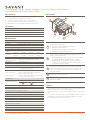
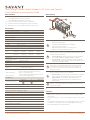
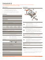
A
Multi-Page LCD screen that oers the following information:
–Real-time energy usage.
–Firmware and Mac Address of the module.
–UID of the connected Host
–Real-time Bluetooth status connectivity icon.
–Module set-up and calibration screens.
B
PAIR Button - The PAIR button is a multi-use button. The
duration that the button is pressed and held determines the
function that gets initiated:
– Press and Release - Cycles through the screens available
on the LCD (POWER > POWER > INFO 1 > INFO 2).
– Press and hold - Press and hold for 2 second to put the
module into pairing mode. Press and hold for greater than
5 seconds to reset the module.
C
CT Connections - Connect a current transformer to each CT
Connection input port labeled 1 and 2, observing polarity
when making connections. Refer to the Install the Current
Transformer section later in the document for additional
wiring information.
DPigtail Neutral - Connect the pigtail type neutral wire to the
neutral bar in the breaker panel.
E120V AC Connection - Plug the module onto the 120V AC
bus bar in the breaker panel. The voltage on this connection
powers the module.
Minimum Supported Release
Savant OS da Vinci 10.x
Electrical and Safety Characteristics
Pollution Degree 2
Purpose of Control Energy Monitoring
Software Class A
Impulse Voltage 2500V
Standards
Wireless Bluetooth 5 Low Energy (BLE)
–2.4 GHz radio frequency
This meter will be tested and certified to the following standards:
ANSI C12.20-2015 American National Standard for Electricity
Meters - 0.5 Accuracy Class
ANSI C12.1-2014 American National Standard for Electric Meters
- Code of electricity Metering
Regulatory
Safety and Emissions
FCC Part 15 UL ICES 003
Contains FCC ID: PUU-HQC2SEM
Contains IC: 10798A-HQC2SEM
RoHS Compliant
Recommended Load Center Types
Refer to the Features section to the right for compatibility.
Power
Input Power
(powers the module) 120V AC (+/- 10%) @ 60 Hz, 0.1A (max)
Signal Input 0.333V AC @ 60Hz
Type of Action Type 1 action
Dimensions and Weights
Length Width Height Weight
Module 4.49 in.
(11.41 cm)
1.98 in.
(5.03 cm)
2.78 in.
(7.06 cm)
.54 lbs
(.24 kg)
Shipping 7.48 in.
(19.0 cm)
4.17 in.
(10.6 cm)
1.69 in.
(4.29 cm)
1.0 lbs.
(.45 kg)
Environmental
Temperature 32° to 104° F (0° to 40° C)
Humidity 5% to 85% Relative Humidity (non-condensing)
Location Indoor Use Only
Current Transformers
–ACTL-1250-250 Opt CO.2 250 Amp
–ACTL-1250-400 Opt CO.2 400 Amp
–ACTL-1250-600 Opt CO.2 600 Amp
Features
–The GPM-H2SEM-00 Smart Energy Monitor modules is compatible
with Schneider Homeline, Eaton BR, Siemens, and Powermark Gold
load centers with a one-inch on-center bus bar.
–Energy monitoring; +/- 0.5% revenue grade accuracy / 1 sec sample
time.
–The module communicates with a Panel Bridge Controller or Savant
Power Director using Bluetooth Low Energy (BLE) technology.
–Color LCD display for easy identification.
Smart Energy Monitor Module (Supports 1-inch On-Center Load Centers)
Quick Reference and Installation Guide
Specifications
Box Contents
Accessories
Descriptions
(1) Smart Energy Monitor Module (SEM)
–GPM-H2SEM-xx w/Pigtail type neutral
(1) 4-pin screw down plug-in connector (028-9395)
(1) Product Information and Regulatory Insert (009-1950)
(1) Quick Reference and Installation Guide (this document)
Construction of Control
Open Type Independently mounted for flush mounting

Smart Energy Monitor - QRG | 009-2245-00 2 of 4 45 Perseverance Way, Hyannis MA 02601
Copyright ©2022 Savant Systems, Inc | 220930 Savant.com | 508.683.2500
–Each Smart Energy Monitor requires two spaces in an electrical breaker panel.
–All wiring in the United States must be installed in accordance with the latest adopted edition of the National Electrical Code
(ANSI/NFPA 70, NEC)
–All wiring in Canada must be installed in accordance with the latest adopted edition of the Canadian Electrical Code (CSA C222.2 CEC, Part 1)
and any provincial or local requirements.
–Use only Savant approved current transformers. A list of supported transformers is available in the Accessories section on the previous page.
–The largest current transformer oered from Savant supports wire up to a 750 kcmil conductor (with jacket is just under 1 inch in diameter).
Important Information
ELECTRIC SHOCK! The 120V AC, 60 Hz source poses an electrical
shock hazard that has the potential to cause serious injury to
installers and end users.
IMPORTANT! A licensed electrician is required to install any of
Savant’s Power and Energy Monitoring Modules.
CAUTION! Risk of Electric Shock - More than one disconnect
switch may be required to de-energize the device before
servicing. Always disconnect the power to the module before
making any connections.
1. Remove power from the breaker panel by switching o the panel’s main breaker.
2. Position and install the Smart Energy Monitor Module into the slots where it will be installed. Press firmly until fully seated onto the
appropriate bus bars.
3. The next few sections describe how to install and wire a current transformer to the Smart Energy Monitor module.
1. Toggle the electrical panel’s main breaker O to remove power
from the panel.
2. Remove the panel’s front cover and set it aside. Verify that power is
removed from the circuit breakers using a voltage tester.
3. Separate the current transformer by squeezing the knurled panel
and pulling/rotating the top open.
4. Place the current transformers around each of the conductors
being monitored.
–Orient the current transformer so the arrow in the middle
points towards the source i.e., breaker or utility meter.
5. Close the current transformer around the conductor. For added
security, wrap a cable tie around the CT or run the tie through the
loop on the front.
6. Route the twisted black and white wires around the breaker panel
back to the Smart Energy Monitor module. Route the wires so they
don’t directly come in contact with a live bus bar or terminal.
7. Observing polarity, insert the wires into the supplied 4-pin
connector and secure by turning screws clockwise. See the Making
Connections section in this document for information on attaching
wires to the connector.
8. Repeat steps 3-7 to install a second current transformer if needed.
9. Ensure the 4-pin connector is fully seated into the SEM module and
tighten the screws to .18 ft-lb (.25 N-m) max.
10. Toggle the main breaker back to the On position and re-apply
power to the electrical panel. The Current Transformer and Smart
Energy Monitor module are ready to monitor the power consumed
by the circuit the CT is monitoring.
–Savant Power Deployment Guide - Sol-Ark
Installation into Breaker Panel
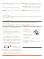
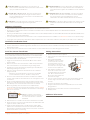
Install the Current Transformer Making Connections
Additional Information
The GPM-H2SEM module supports connecting up to two Savant-
approved current transformers. See the approved list on the previous
page. Instructions on wiring and orienting the current transformer are
explained below.
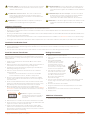
(+)
POS
White Black BlackWhite
(+)
POS
(-)
GND
(-)
GND
CT1 CT2
1. Remove power if power is applied.
2. Pull to remove the terminal block from the Smart Energy Monitor’s
rear panel.
3. With a small flat-bladed
screwdriver, turn the screws
on the top of the connector
counterclockwise until the
silver crimps on the front of the
connector open enough to slide
the wire into the square slot.
4. Strip back the insulation of each
wire to ¼ inch (6.5 mm). Insert
the stripped wire into the proper
port. Do not allow more than
⅛ inch (3.2 mm) of bare wire
exposed. See image.
5. Turn the screws clockwise until the silver crimps tighten around
the wire. Tug on the wire a bit to verify the wire is installed
securely.
6. Continue until all wires are installed.
7. Plug the terminal block into the appropriate port on the Smart
Energy Monitor.
8. Repeat steps 2-7 for all wires from the current transformer.
9. Reapply power.
Less than
⅛ inch bare
wire exposed
HELPFUL: A negative current will be
measured if the wires are reversed or
the current transformer is installed
backward.
CHOC ÉLECTRIQUE! La source alimentation électrique de 120 V
AC, 60 Hz présente un risque d’électrocution susceptible de
causer des blessures graves aux installateurs et aux utilisateurs
finaux.
IMPORTANT! Un électricien agréé est requis pour installer l’un des
modules de surveillance de l’alimentation et de l’énergie de
Savant.
ATTENTION! Risque de choc électrique - Plus d’un interrupteur
de déconnexion peut être nécessaire pour mettre l’appareil
hors tension avant l’entretien. Débranchez toujours
l’alimentation du module avant d’eectuer des connexions.

Smart Energy Monitor - QRG | 009-2245-00 3 of 4 45 Perseverance Way, Hyannis MA 02601
Copyright ©2022 Savant Systems, Inc | 220930 Savant.com | 508.683.2500
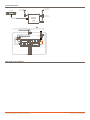
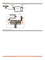
System Overview
SEM Display Descriptions
Bluetooth to
SEM Modules
Bluetooth to
SEM Modules
SEM Module Commuicates with
Director or PBC over Bluetooth
Power From
the Utility
Wi-Fi
(if needed)
Local Lan
Breaker Panel
MAIN
BREAKER
BREAKER
BREAKER
BREAKER
BREAKER
PAIR
SMART ENERGY
MONITOR
GPM-H2SEM
CT CONNECTIONS
1
+-
2
+-
PAIR
SMART ENERGY
MONITOR
GPM-H2SEM
CT CONNECTIONS
1
+-
2
+-
Current Transformers
Current Transformers
Current Transformers
(Twisted Pair)
Current Transformers
(Twisted Pair)


Smart Energy Monitor (QO) - QRG | 009-2240-00 1 of 4 45 Perseverance Way, Hyannis MA 02601
Copyright ©2022 Savant Systems, Inc | 221005 Savant.com | 508.683.2500
DO NOT
PRESS ON
SCREEN
REMOVE AFTER
INSTALLATION
PAIR
D
A
B
C
E
GPM-Q2SEM
MODULE INPUT: 120VAC 60Hz
SERIAL INPUT: 0.333vac 60Hz
#18-24 AWG Min. 105°C Cu Only
IC 10798A-HQCSEM
FCC ID PUU-HQCSEM
INDOOR USE ONLY
CT CONNECTIONS
12
+
-
+
-
SMART ENERGY MONITOR
OOOO
A
Multi-Page LCD screen that oers the following information:
–Real-time energy usage.
–Firmware and Mac Address of the module.
–UID of the connected Host
–Real-time Bluetooth status connectivity icon.
–Module set-up and calibration screens.
B
PAIR Button - The PAIR button is a multi-use button. The
duration that the button is pressed and held determines the
function that gets initiated:
– Press and Release - Cycles through the screens available
on the LCD (POWER > POWER > INFO 1 > INFO 2).
– Press and hold - Press and hold for 2 second to put the
module into pairing mode. Press and hold for greater than
5 seconds to reset the module.
C
CT Connections - Connect a current transformer to each CT
Connection input port labeled 1 and 2, observing polarity
when making connections. Refer to the Install the Current
Transformer section later in the document for additional
wiring information.
D
Neutral - The model number of the module determines the
type of neutral connection on the module:
– Plug-on Neutral - Positioned on the bottom of the module
is a neutral clip that plugs directly onto the neutral bar.
– Pigtail Neutral - A neutral wire protrudes from the
module’s rear and gets wired to the neutral bar in the
breaker panel.
E120V AC Connection - Plug the module onto the 120V AC
bus bar in the breaker panel. The voltage on this connection
powers the module.
Minimum Supported Release
Savant OS da Vinci 10.x
Electrical and Safety Characteristics
Pollution Degree 2
Purpose of Control Energy Monitoring
Software Class A
Impulse Voltage 2500V
Standards
Wireless Bluetooth 5 Low Energy (BLE)
–2.4 GHz radio frequency
This meter will be tested and certified to the following standards:
ANSI C12.20-2015 American National Standard for Electricity
Meters - 0.5 Accuracy Class
ANSI C12.1-2014 American National Standard for Electric Meters
- Code of electricity Metering
Regulatory
Safety and Emissions
FCC Part 15 UL ICES 003
Contains FCC ID: PUU-HQC2SEM
Contains IC: 10798A-HQC2SEM
RoHS Compliant
Recommended Load Center Types
Refer to the Features section to the right for compatibility.
Power
Input Power
(powers the module) 120V AC (+/- 10%) @ 60 Hz, 0.1A (max)
Signal Input 0.333V AC @ 60Hz
Type of Action Type 1 action
Dimensions and Weights
Length Width Height Weight
Module
(QO)
4.97 in.
(12.63 cm)
1.45 in.
(3.68 cm)
2.60 in.
(6.61 cm)
.5 lbs
(.23 kg)
Shipping 7.50 in.
(19.05 cm)
4.30 in.
(10.92 cm)
1.71 in.
(4.34 cm)
1.0 lbs.
(.45 kg)
Environmental
Temperature 32° to 104° F (0° to 40° C)
Humidity 5% to 85% Relative Humidity (non-condensing)
Location Indoor Use Only
Current Transformers
–ACTL-1250-250 Opt CO.2 250 Amp
–ACTL-1250-400 Opt CO.2 400 Amp
–ACTL-1250-600 Opt CO.2 600 Amp
Features
–The GPM-Q2SEM-00 and GPM-QP2SEM Smart Energy Monitor
modules are compatible with Schneider/Electric Square D™ QO™
load centers.
–Energy monitoring; +/- 0.5% revenue grade accuracy / 1 sec sample
time.
–The module communicates with a Panel Bridge Controller or Savant
Power Director using Bluetooth Low Energy (BLE) technology.
–Color LCD display for easy identification.
Smart Energy Monitor Module (Supports QO Style Load Centers)
Quick Reference and Installation Guide
Specifications
Box Contents
Accessories
Descriptions
(1) Smart Energy Monitor Module (SEM)
–GPM-QP2SEM-xx w/Plug-on neutral
–GPM-Q2SEM-xx w/Pigtail type neutral
(1) 4-pin screw down plug-in connector (028-9395)
(1) Product Information and Regulatory Insert (009-1950)
(1) Quick Reference and Installation Guide (this document)
Construction of Control
Open Type Independently mounted for flush mounting

Smart Energy Monitor (QO) - QRG | 009-2240-00 2 of 4 45 Perseverance Way, Hyannis MA 02601
Copyright ©2022 Savant Systems, Inc | 221005 Savant.com | 508.683.2500
–Each Smart Energy Monitor requires two spaces in an electrical breaker panel.
–All wiring in the United States must be installed in accordance with the latest adopted edition of the National Electrical Code
(ANSI/NFPA 70, NEC)
–All wiring in Canada must be installed in accordance with the latest adopted edition of the Canadian Electrical Code (CSA C222.2 CEC, Part 1)
and any provincial or local requirements.
–Use only Savant approved current transformers. A list of supported transformers is available in the Accessories section on the previous page.
–The largest current transformer oered from Savant supports wire up to a 750 kcmil conductor (with jacket is just under 1 inch in diameter).
Important Information
ELECTRIC SHOCK! The 120V AC, 60 Hz source poses an
electrical shock hazard that has the potential to cause serious
injury to installers and end users.
IMPORTANT! A licensed electrician is required to install any of
Savant’s Power and Energy Monitoring Modules.
CAUTION! Risk of Electric Shock - More than one disconnect
switch may be required to de-energize the device before
servicing. Always disconnect the power to the module before
making any connections.ring Modules.
1. Remove power from the breaker panel by switching o the panel’s main breaker.
2. Position and install the Smart Energy Monitor Module into the slots where it will be installed. Press firmly until fully seated onto the
appropriate bus bars.
3. The next few sections describe how to install and wire a current transformer to the Smart Energy Monitor module.
1. Toggle the electrical panel’s main breaker O to remove power
from the panel.
2. Remove the panel’s front cover and set it aside. Verify that power is
removed from the circuit breakers using a voltage tester.
3. Separate the current transformer by squeezing the knurled panel
and pulling/rotating the top open.
4. Place the current transformers around each of the conductors
being monitored.
–Orient the current transformer so the arrow in the middle
points towards the source i.e., breaker or utility meter.
5. Close the current transformer around the conductor. For added
security, wrap a cable tie around the CT or run it through the loops
on the front.
6. Route the twisted black and white wires around the breaker panel
back to the Smart Energy Monitor module. Route the wires so they
don’t directly come in contact with a live bus bar or terminal.
7. Observing polarity, insert the wires into the supplied 4-pin
connector and secure by turning screws clockwise. See the Making
Connections section in this document for more information on
attaching the wires to the connector.
8. Repeat steps 3-7 to install a second current transformer if needed.
9. Ensure the 4-pin connector is fully seated into the SEM module and
tighten the connector’s mounting screws to .18 ft-lb (.25 N-m) max.
10. Toggle the main breaker back to the On position and re-apply
power to the electrical panel. The Current Transformer and Smart
Energy Monitor module are ready to monitor the power consumed
by the circuit the CT is monitoring.
Installation into Breaker Panel
Install the Current Transformer Making Connections
Additional Information
The GPM-Q2SEM and GPM-QP2SEM module supports connecting up
to two Savant-approved current transformers. See the approved list on
the previous page. Instructions on wiring and orienting the transformer
are explained below.
(+)
POS
White Black BlackWhite
(+)
POS
(-)
GND
(-)
GND
CT1 CT2
1. Remove power if power is applied.
2. Pull to remove the terminal block from the Smart Energy Monitor’s
rear panel.
3. With a small flat-bladed
screwdriver, turn the screws
on the top of the connector
counterclockwise until the
silver crimps on the front of the
connector open enough to slide
the wire into the square slot.
4. Strip back the insulation of each
wire to ¼ inch (6.5 mm). Insert
the stripped wire into the proper
port. Do not allow more than
⅛ inch (3.2 mm) of bare wire
exposed. See image.
5. Turn the screws clockwise until the silver crimps tighten around
the wire. Tug on the wire a bit to verify the wire is installed
securely.
6. Continue until all wires are installed.
7. Plug the terminal block into the appropriate port on the Smart
Energy Monitor.
8. Repeat steps 2-7 for all wires from the current transformer.
9. Reapply power.
Less than
⅛ inch bare
wire exposed
HELPFUL: A negative current will be
measured if the wires are reversed
or the current transformer is
installed backward. –Savant Power Deployment Guide - Sol-Ark
CHOC ÉLECTRIQUE! La source alimentation électrique de 120 V
AC, 60 Hz présente un risque d’électrocution susceptible de
causer des blessures graves aux installateurs et aux utilisateurs
finaux.
IMPORTANT! Un électricien agréé est requis pour installer l’un des
modules de surveillance de l’alimentation et de l’énergie de
Savant.
ATTENTION! Risque de choc électrique - Plus d’un interrupteur
de déconnexion peut être nécessaire pour mettre l’appareil
hors tension avant l’entretien. Débranchez toujours
l’alimentation du module avant d’eectuer des connexions.

Smart Energy Monitor (QO) - QRG | 009-2240-00 3 of 4 45 Perseverance Way, Hyannis MA 02601
Copyright ©2022 Savant Systems, Inc | 221005 Savant.com | 508.683.2500
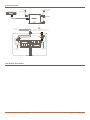
System Overview
SEM Display Descriptions
Bluetooth to
SEM Modules
Bluetooth to
SEM Modules
SEM Module Commuicates with a
Director/Directlite or PBC over Bluetooth
Power From
the Utility
Wi-Fi
(if needed)
Local Lan
Electrical Panel
MAIN
BREAKER
BREAKER
BREAKER
BREAKER
BREAKER
PAIR
SMART ENERGY
MONITOR
GPM-Q2SEM
CT CONNECTIONS
1
+-
2
+-
PAIR
SMART ENERGY
MONITOR
GPM-Q2SEM
CT CONNECTIONS
1
+-
2
+-
Current Transformers
Current Transformers
Current Transformer
Cables
(Twisted Pair)
Current Transformer
Cable
(Twisted Pair)


Smart Energy Monitor - QRG | 009-2241-00 1 of 4 45 Perseverance Way, Hyannis MA 02601
Copyright ©2022 Savant Systems, Inc | 220930 Savant.com | 508.683.2500
DO NOT
PRESS ON
SCREEN
REMOVE AFTER
INSTALLATION
PAIR
C
D
A
B
E
GPM-C2SEM
MODULE INPUT: 120VAC 60Hz
SERIAL INPUT: 0.333vac 60Hz
#18-24 AWG Min. 105°C Cu Only
IC 10798A-HQCSEM
FCC ID PUU-HQCSEM
INDOOR USE ONLY
CT CONNECTIONS
12
+
-
+
-
SMART ENERGY MONITOR
OOOO
A
Multi-Page LCD screen that oers the following information:
–Real-time energy usage.
–Firmware and Mac Address of the module.
–UID of the connected Host
–Real-time Bluetooth status connectivity icon.
–Module set-up and calibration screens.
B
PAIR Button - The PAIR button is a multi-use button. The
duration that the button is pressed and held determines the
function that gets initiated:
– Press and Release - Cycles through the screens available
on the LCD (POWER > POWER > INFO 1 > INFO 2).
– Press and hold - Press and hold for 2 second to put the
module into pairing mode. Press and hold for greater than
5 seconds to reset the module.
C
CT Connections - Connect a current transformer to each CT
Connection input port labeled 1 and 2, observing polarity
when making connections. Refer to the Install the Current
Transformer section later in the document for additional
wiring information.
D
Neutral - The model number of the module determines the
type of neutral connection:
– Plug-on Neutral - Positioned on the bottom of the module
is a neutral clip that plugs directly onto the neutral bar.
– Pigtail Neutral - A neutral wire protrudes from the
module’s rear and gets wired to the neutral bar in the
breaker panel.
E120V AC Connection - Plug the module onto the 120V AC
bus bar in the breaker panel. The voltage on this connection
powers the module.
Minimum Supported Release
Savant OS da Vinci 10.x
Electrical and Safety Characteristics
Pollution Degree 2
Purpose of Control Energy Monitoring
Software Class A
Impulse Voltage 2500V
Standards
Wireless Bluetooth 5 Low Energy (BLE)
–2.4 GHz radio frequency
This meter will be tested and certified to the following standards:
ANSI C12.20-2015 American National Standard for Electricity
Meters - 0.5 Accuracy Class
ANSI C12.1-2014 American National Standard for Electric Meters
- Code of electricity Metering
Regulatory
Safety and Emissions
FCC Part 15 UL ICES 003
Contains FCC ID: PUU-HQC2SEM
Contains IC: 10798A-HQC2SEM
RoHS Compliant
Recommended Load Center Types
Refer to the Features section to the right for compatibility.
Power
Input Power
(powers the module) 120V AC (+/- 10%) @ 60 Hz, 0.1A (max)
Signal Input 0.333V AC @ 60Hz
Type of Action Type 1 action
Dimensions and Weights
Length Width Height Weight
Module 4.49 in.
(11.4 cm)
1.97 in.
(5.0 cm)
2.76 in.
(7.0 cm)
.5 lbs
(.23 kg)
Shipping 7.48 in.
(19.0 cm)
4.17 in.
(10.60 cm)
1.69 in.
(4.29 cm)
1.0 lbs.
(.45 kg)
Environmental
Temperature 32° to 104° F (0° to 40° C)
Humidity 5% to 85% Relative Humidity (non-condensing)
Location Indoor Use Only
Current Transformers
–ACTL-1250-250 Opt CO.2 250 Amp
–ACTL-1250-400 Opt CO.2 400 Amp
–ACTL-1250-600 Opt CO.2 600 Amp
Features
–All Eaton CH style Smart Energy Modules are compatible with
Eaton CH ¾ inch load centers.
–Energy monitoring; +/- 0.5% revenue grade accuracy / 1 sec sample
time.
–The module communicates with a Panel Bridge Controller or Savant
Power Director using Bluetooth Low Energy (BLE) technology.
–Color LCD display for easy identification.
Smart Energy Monitor Module (Supports Eaton CH Style Load Centers)
Quick Reference and Installation Guide
Specifications
Box Contents
Accessories
Descriptions
(1) Smart Energy Monitor Module (SEM)
–GPM-CP2SEM-xx w/Plug-on type neutral
–GPM-C2SEM-xx w/Pigtail type neutral
(1) 4-pin screw down plug-in connector (028-9395)
(1) Product Information and Regulatory Insert (009-1950)
(1) Quick Reference and Installation Guide (this document)
Construction of Control
Open Type Independently mounted for flush mounting

Smart Energy Monitor - QRG | 009-2241-00 2 of 4 45 Perseverance Way, Hyannis MA 02601
Copyright ©2022 Savant Systems, Inc | 220930 Savant.com | 508.683.2500
–Each Smart Energy Monitor requires two spaces in an electrical breaker panel.
–All wiring in the United States must be installed in accordance with the latest adopted edition of the National Electrical Code
(ANSI/NFPA 70, NEC)
–All wiring in Canada must be installed in accordance with the latest adopted edition of the Canadian Electrical Code (CSA C222.2 CEC, Part 1)
and any provincial or local requirements.
–Use only Savant approved current transformers. A list of supported transformers is available in the Accessories section on the previous page.
–The largest current transformer oered from Savant supports wire up to a 750 kcmil conductor (with jacket is just under 1 inch in diameter).
Important Information
ELECTRIC SHOCK! The 120V AC, 60 Hz source poses an
electrical shock hazard that has the potential to cause serious
injury to installers and end users.
IMPORTANT! A licensed electrician is required to install any of
Savant’s Power and Energy Monitoring Modules.
CAUTION! Risk of Electric Shock - More than one disconnect
switch may be required to de-energize the device before
servicing. Always disconnect the power to the module before
making any connections.
1. Remove power from the breaker panel by switching o the panel’s main breaker.
2. Position and install the Smart Energy Monitor Module into the slots where it will be installed. Press firmly until fully seated onto the
appropriate bus bars.
3. The next few sections describe how to install and wire a current transformer to the Smart Energy Monitor module.
1. Toggle the electrical panel’s main breaker O to remove power
from the panel.
2. Remove the panel’s front cover and set it aside. Verify that power
was removed from the circuit breakers using a voltage tester.
3. Separate the current transformer by squeezing the knurled panel
and pulling/rotating the top open.
4. Place the current transformers around each of the conductors
being monitored.
–Orient the current transformer so the arrow in the middle
points towards the source i.e., breaker or utility meter.
5. Close the current transformer around the conductor. For added
security, wrap a cable tie around the CT or run it through the loops
on the front.
6. Route the twisted black and white wires around the breaker panel
back to the Smart Energy Monitor module. Route the wires so they
don’t directly come in contact with a live bus bar or terminal.
7. Observing polarity, insert the wires into the supplied 4-pin
connector and secure by turning screws clockwise. See the Making
Connections section in this document for information on attaching
wires to the connector.
8. Repeat steps 3-7 to install a second current transformer if needed.
9. Ensure the 4-pin connector is fully seated into the SEM module and
tighten to .18 ft-lb (.25 N-m) max.
10. Toggle the main breaker back to the On position and re-apply
power to the electrical panel. The Current Transformer and Smart
Energy Monitor module are ready to monitor the power consumed
by the circuit the CT is monitoring.
Installation into Breaker Panel
Install the Current Transformer Making Connections
Additional Information
The GPM-C2SEM and GPM-CP2SEM modules support connecting up
to two Savant-approved current transformers. See the approved list
on the previous page. Information on connecting and orienting the
current transformer is explained below.
(+)
POS
White Black BlackWhite
(+)
POS
(-)
GND
(-)
GND
CT1 CT2
1. Remove power if power is applied.
2. Pull to remove the terminal block from the Smart Energy Monitor’s
rear panel.
3. With a small flat-bladed
screwdriver, turn the screws
on the top of the connector
counterclockwise until the
silver crimps on the front of the
connector open enough to slide
the wire into the square slot.
4. Strip back the insulation of each
wire to ¼ inch (6.5 mm). Insert
the stripped wire into the proper
port. Do not allow more than
⅛ inch (3.2 mm) of bare wire
exposed. See image.
5. Turn the screws clockwise until the silver crimps tighten around
the wire. Tug on the wire a bit to verify the wire is installed
securely.
6. Continue until all wires are installed.
7. Plug the terminal block into the appropriate port on the Smart
Energy Monitor.
8. Repeat steps 2-7 for all wires from the current transformer.
9. Reapply power.
Less than
⅛ inch bare
wire exposed
HELPFUL: A negative current will be
measured if the wires are reversed or
the current transformer is installed
backward.
–Savant Power Deployment Guide - Sol-Ark
CHOC ÉLECTRIQUE! La source alimentation électrique de 120 V
AC, 60 Hz présente un risque d’électrocution susceptible de
causer des blessures graves aux installateurs et aux utilisateurs
finaux.
IMPORTANT! Un électricien agréé est requis pour installer l’un des
modules de surveillance de l’alimentation et de l’énergie de
Savant.
ATTENTION! Risque de choc électrique - Plus d’un interrupteur
de déconnexion peut être nécessaire pour mettre l’appareil
hors tension avant l’entretien. Débranchez toujours
l’alimentation du module avant d’eectuer des connexions.

Smart Energy Monitor - QRG | 009-2241-00 3 of 4 45 Perseverance Way, Hyannis MA 02601
Copyright ©2022 Savant Systems, Inc | 220930 Savant.com | 508.683.2500
System Overview
SEM Display Descriptions
Bluetooth to
SEM Modules
Bluetooth to
SEM Modules
SEM Module Commuicates with a
Director/Directlite or PBC over Bluetooth
Power From
the Utility
Wi-Fi
(if needed)
Local Lan
Electrical Panel
MAIN
BREAKER
BREAKER
BREAKER
BREAKER
BREAKER
PAIR
SMART ENERGY
MONITOR
GPM-C2SEM
CT CONNECTIONS
1
+-
2
+-
PAIR
SMART ENERGY
MONITOR
GPM-C2SEM
CT CONNECTIONS
1
+-
2
+-
Current Transformers
Current Transformers
Current Transformer
Cables
(Twisted Pair)
Current Transformer
Cable
(Twisted Pair)

-
 1
1
-
 2
2
-
 3
3
-
 4
4
-
 5
5
-
 6
6
-
 7
7
-
 8
8
-
 9
9
-
 10
10
-
 11
11
-
 12
12
-
 13
13
-
 14
14


dans d''autres langues
- English: Savant GPM-H25SEM Installation guide
Documents connexes
-
Savant QP1R30240 Guide d'installation
-
Savant QP2APD10 Manuel utilisateur
-
Savant HST-STUDIO55WS-SUR-00 Guide de référence
-
-
-
-
-
-
Savant REM-2000I-00 Guide de référence
-