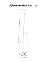
MartinLogan ElectroMotion ESL X Manuel utilisateur
- Taper
- Manuel utilisateur

user’s manual
®

2
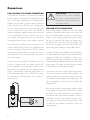
The lightning bolt flash with arrowhead
symbol, within an equilateral triangle,
is intended to alert the user to the
presence of potentially “dangerous voltage” within the
product’s enclosure that may be sufficient to constitute
a risk of electric shock.
The exclamation point within an
equilateral triangle is intended to alert
the user to the presence of important
operating and maintenance (servicing) instructions in
the literature accompanying the appliance.
In accordance with the European Union
WEEE (Waste Electrical and Electronic
Equipment) directive effective August 13,
2005, we would like to notify you that
this product may contain regulated materials which
upon disposal, according to the WEEE directive,
require special reuse and recycling processing.
For this reason Martin Logan has arranged with our
distributors in European Union member nations to
collect and recycle this product at no cost to you.
To find your local distributor contact the dealer from whom
you purchased this product, email [email protected]
or visit the distributor locator at www.martinlogan.com.
Please note, only this product itself falls under the
WEEE directive. When disposing of packaging and
other related shipping materials we encourage you to
recycle these items through the normal channels.
Installation in Brief ..................... 4
Introduction .......................... 5
Connections .........................6
Low-Voltage (DC) Power Connection .......6
Speaker Level Conneciton ..............6
Jumper Clips .......................7
Single Wire Connection ...............7
Bi-wire Connection ..................7
Passive Bi-amplification ................7
Active Bi-amplification ................8
Placement & Room Acoustics .............8
Listening Position ....................8
The Wall Behind the Listener ............8
The Wall Behind the Speakers ..........8
The Side Walls ....................8
Experimentation ....................9
Final Placement ...................11
The Extra “Tweak” .................11
Room Acoustics ......................13
Your Room .......................13
Terminology ......................13
Rules of Thumb ...................13
Dipolar Speakers and Your Room ........14
Solid Footing .....................14
Dispersion Interactions ................. 15
Controlled Horizontal Dispersion ........15
Controlled Vertical Dispersion ..........15
Three Major Types of Dispersion ........15
Home Theater .......................16
Electrostatic Advantages ...............17
MartinLogan Exclusives ................18
Full Range Operation ................18
CLS™ (Curvilinear Line Source) .........19
XStat Transducer ...................20
MicroPerf Stator ...................20
Vacuum Bonding ...................20
AirFrame™ Technology ..............20
Electrostatic Loudspeaker History .........20
Frequently Asked Questions .............23
Troubleshooting ...................... 25
General Information ..................26
Warranty and Registration ............26
Serial Number ....................26
Service .........................26
Specifications .......................27
Glossary of Audio Terms ...............27
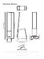
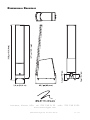
Dimensional Drawings .................30
WARNING! Do not use your EM-ESL
X loudspeakers outside of the country
of original sale—voltage requirements
vary by country. Improper voltage can cause
damage that will be potentially expensive to repair.
The EM-ESL X is shipped to authorized MartinLogan
distributors with the correct power supply for use
in the country of intended sale. A list of authorized
distributors can be accessed at www.martinlogan.
com or by e-mailing info@martinlogan.

Serial Number:_____________________________
Record your serial number here for easy reference. You will need this information when filling out your
warranty registration. The serial number is located near the binding posts and on the product carton.
x 1
3

4
We know you are eager to hear your new
ElectroMotion ESL X (EM-ESL X) speakers, so this
section is provided to allow fast and easy set up.
Once you have them operational, please take the
time to read, in depth, the rest of the information in
this manual. It will give you perspective on how to
attain the greatest possible performance from this
most exacting transducer.
If you should experience any difficulties in the setup
or operation of your EM-ESL X speakers, please
refer to the Room Acoustics, Placement or Operation
sections of this manual. Should you encounter a
persistent problem that cannot be resolved, please
contact your authorized MartinLogan dealer. They
will provide you with the appropriate technical anal-
ysis to alleviate the situation.
WARNING!
• Hazardous voltages exist
inside—do not remove cover.
• Refer servicing to a qualified
technician.
• To prevent fire or shock hazard, do not
expose this module to moisture.
• Turn amplifier off and unplug speaker
should any abnormal conditions occur.
• Turn amplifier off before making or
breaking any signal connections!
• Do not operate if there is any visual
damage to the electrostatic panel element.
• Do not drive speaker beyond its rated power.
• The power cord should not be installed,
removed, or left detached from the speaker
while the other end is connected to an AC
power source.
• No candles or other sources of open flame
should be placed on the speaker.
• No liquids either in glasses or vases should
be placed on speaker.
• Speaker should not be exposed to dripping
or splashing liquids.
• The terminals marked with the lightning bolt
symbol should be connected by an instructed
person or by way of ready made terminals.
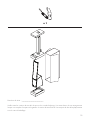
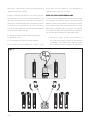
Step 1: Unpacking
Remove your new EM-ESL X speakers from their
packaging.
Step 2: Placement
Place each EM-ESL X at least two feet from the
back wall and angle them slightly toward your
listening area. This is a good place to start. Please
see the Placement section of this manual for more
details.
Step 3: Power Connection (see warning)
Your EM-ESL X speakers require power to energize
their electrostatic cells. Using the power cords
provided, plug them in first to the power receptacle
on the rear panel of the speaker, making sure that
you have made a firm connection, and then to a
wall outlet. Please see Low-Voltage (DC) Power
Connection (page 6) for more details.
InstallatIon In BrIef
WARNING! Do not use your EM-ESL X loudspeakers outside of the country of
original sale—voltage requirements vary by country. Improper voltage can cause
damage that will be potentially expensive to repair. The EM-ESL X is shipped to
authorized MartinLogan distributors with the correct power supply for use in the
country of intended sale. A list of authorized distributors can be accessed at www.
martinlogan.com or by emailing [email protected].

5
Step 4: Signal Connection
Use the best speaker cables you can. Higher
quality cables, available from your specialty
dealer, are recommended and will give you
superior performance.
Attach your speaker cables to the signal input
section on the rear panel. Be consistent when
connecting speaker leads to the terminals on the
back of the EM-ESL X. Take great care to assign
the same color to the (+) terminal on both the left
and right channels. If bass is nonexistent and you
cannot discern a tight, coherent image, you may
need to reverse the (+) and (–) leads on one side
to bring the system into proper polarity.
For detailed setup instructions, please turn to the
Speaker Level Connection section (page 6) of this
manual for more details.
Step 5: Listen and Enjoy
Now, you may turn on your system and enjoy!
Congratulations! You have invested in one of the
world’s premier speaker systems.
The ElectroMotion ESL X (EM-ESL X) represents
an advanced combination of sonic technologies
establishing an unprecedented direction for
audiophile design. The result of years of research,
the new EM-ESL X hybrid electrostatic loudspeaker
delivers new standards for efficiency, dynamics
and precision in a floor standing loudspeaker.
Housed within a radical, ultra-rigid extruded
aluminum and composite AirFrame™, the EM-ESL
X’s CLS XStat™ transducer builds upon the legacy
of MartinLogan’s electrostatic heritage with the
incorporation of advanced vacuum bonding and
MicroPerf stat panels, providing even greater
efficiency and precision. The integration electrical
interface technology developed by MartinLogan’s
CLX engineering team extends effortless dynamics
and purity, resulting in even higher sonic standards
of efficiency and precision.
Featuring an advanced crossover topology,
MartinLogan carefully builds each EM-ESL X
crossover utilizing precision components to
flawlessly preserve sonic subtleties while effortlessly
handling the broadest range of dynamics
contained within even the most demanding sonic
source.
The materials in your new EM-ESL X speakers are
of the highest quality and will provide years of
enduring enjoyment and deepening respect. The
cabinetry is constructed from the highest quality
composite material for acoustical integrity.
Through rigorous testing, the curvilinear electrostatic
panel has proven itself to be one of the most
durable and reliable transducers available today.
Fabricated from a custom tool punched high-grade
steel, the patented panel is then coated with a
special polymer that is applied via a proprietary
electrostatic bonding process. This panel assembly
houses a membrane just 0.0005 of an inch thick.
The other sections of your User’s Manual explain
in detail the operation of your EM-ESL X speakers
and the philosophy applied to their design. A clear
understanding of your speakers will insure that you
obtain maximum performance and pleasure from
this most exacting transducer. It has been designed
and constructed to give you years of trouble-free
listening enjoyment.
IntroductIon

6
connectIons
LOW-VOLTAGE (DC) POWER CONNECTION
Your EM-ESL X speakers use external low-voltage
power supplies to energize their electrostatic pan-
els. For this reason the proper low-voltage power
supplies are provided. A power supply should be
firmly inserted into the ‘DC Power In’ receptacle on
the rear connection panel of each speaker, then
to any convenient AC wall outlet. Your EM-ESL X
speakers integrate a signal sensing circuit which will
switch the EM-ESL X off after a few minutes of no
music signal, and requires less than two seconds to
recharge the panels when a music signal is present.
Your EM-ESL X speakers are provided with a
power supply for the power service supplied in the
country of original consumer sale. The AC power
requirements applicable to a particular unit is
specified both on the packing carton and on the
DC power supply.
If you remove your EM-ESL X speakers from the
country of original sale, be certain that the AC
power supplied in any subsequent location is suit-
able before connecting the low-voltage power
supply. Substantially impaired performance or
severe damage may occur to a EM-ESL X speak-
er if operation is attempted from an incorrect AC
power source.
WARNING! The DC power
supply should not be installed,
removed, or left detached from
the speaker while connected to an
AC power source.
SPEAKER LEVEL CONNECTION
Use the best speaker cables you can. The length
and type of speaker cable used in your system will
have an audible effect. Under no circumstance
should a wire of gauge higher (thinner) than #16
be used. In general, the longer the length used,
the greater the necessity of a lower gauge, and
the lower the gauge, the better the sound, with
diminishing returns setting in around #8 to #12.
A variety of cables are available whose manufactur-
ers claim better performance than standard heavy
gauge wire. We have verified this in many cases,
and the improvements available are often more
noticeable than the differences between wires of dif-
ferent gauge. The effects of cables may be masked
if equipment is not of the highest quality.
Connections are done at the signal input section
on the rear electronics panel of the speaker. Use
spade connectors for optimum contact and ease
of installation. Hand tighten the binding posts, but
do not overtighten—do not use a tool to tighten the
binding posts.
Be consistent when connecting the speaker cables
to the signal input terminals. Take care to assign
the same color cable lead to the (+) terminal on
both the left and right channel speakers. If bass is
nonexistent and you cannot discern a tight, coher-
ent image, you may need to reverse the (+) and
(–) leads on one speaker to bring the system into
proper polarity.
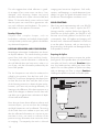
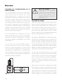
Fig. 1

7
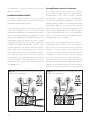
JUMPER CLIPS
In some countries federal law prohibits
MartinLogan from supplying jumper clips. If none
are found installed under your speakers binding
posts, please refer to ‘Bi-Wire Connection’ for con-
nection instructions.
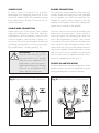
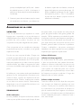
SINGLE WIRE CONNECTION
Please take note of the jumper clips installed
under the binding posts. These clips attach the
high-frequency and low-frequency sections of the
crossover together. Leaving these in place, con-
nect the (+) wire from your amplifier to either red
(+)binding post and the (–) wire from your ampli-
fier to either black (–) binding post (Fig. 2).
WARNING! Only after jumper
clips are removed may you con-
nect individual runs of speaker
cable from your amplifiers to the
high-frequency and low-frequency
signal input binding posts. Damage
will occur to your amplifiers if the
jumper clips are not removed.
BI-WIRE CONNECTION
This connection method replaces the jumper clips
installed under the binding posts with individual
runs of speaker wire from your amplifier. This
doubles the signal carrying conductors from the
amplifier to the speaker, thus direct-coupling each
portion of the crossover to the amplifier.
To bi-wire you must first loosen the binding posts
and remove the jumper clips. Connect one set of
wires to the upper set of binding posts which con-
nect to the high-frequency drivers. Then connect
a second set of wires to the lower binding posts
which connect to the low-frequency drivers. Next,
connect both sets of wires to the appropriate termi-
nals on your amplifier. Please take care to connect
both (+) wires to the (+) amplifier terminals and
both (–) wires to the (–) amplifier terminals. This is
known as a parallel connection (Fig. 3.
PASSIVE BI-AMPLIFICATION
For those that desire ultimate performance, these
speakers may be passively bi-amplified using the
existing internal passive crossover elements.
Fig. 2: Single-wire connection. One channel shown.
Fig. 3: Bi-wire connection. One channel shown.

8
This method takes the bi-wiring concept one step
further. You will have a dedicated channel of
amplification directly connected to the high- and
low-frequency sections of the crossover. There
are two different methods for bi-amping with two
stereo amplifiers. The first and most common is
referred to as Horizontal Bi-amping. The second
method is referred to as Vertical Bi-amping. With
either method you may use two stereo amplifiers or
four mono amplifiers, or two mono amplifiers and
one stereo amplifier. Get the idea? With either
form of passive bi-amplification, your preamplifier
must have dual outputs. If your preamplifier is not
so equipped, you must either purchase or construct
a “Y” adapter.
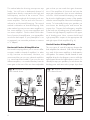
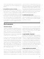
Horizontal Passive Bi-Amplification
Horizontal bi-amping allows you to use two differ-
ent types, models or brands of amplifiers (i.e. tubes
on top, transistor on the bottom). However, we
recommend that you use two identical amplifiers
(i.e. same brand and model). If you must use two
different amplifiers, it is essential that they have the
same gain or that one of the two have adjustable
gain so that you can match their gain character-
istics. If the amplifiers of choice do not have the
same gain characteristics, then a sonic imbalance
will occur. With horizontal bi-amping, one ampli-
fier drives the high-frequency section of the speaker
while the second amplifier drives the low-frequency
section. To horizontally bi-amp your speakers you
must loosen the binding posts and remove the
jumper clips. Connect the low-frequency amplifier
to the lower set of binding posts of both speakers.
Connect the high-frequency amplifier to the upper
set of binding posts. Next, connect the left and
right preamplifier outputs to the appropriate left
and right inputs of both amplifiers (Fig. 4).
Vertical Passive Bi-Amplification
The very nature of vertical bi-amping dictates that
both amplifiers be identical. With vertical bi-amp-
ing, each of the stereo amplifiers is dedicated to
one speaker. For instance, the left channel of each
amplifier drives the low-frequency section while the
right channel drives the high-frequency section. To
vertically bi-amp your speakers you must loosen the
binding posts and remove the jumper clips from
Fig. 4: Horizontal bi-amplification connection.
One channel shown.
Fig. 5: Vertical bi-amplification connection.
One channel shown.

9
Placement
LISTENING POSITION
Your speakers should be placed approximately
two to three feet from the front wall, the wall in
front of the listening position, and about two feet
from the side walls. Your sitting distance should
be further than the distance between the speakers
themselves. You are trying to attain the impression
of good center imaging and stage width.
There is no exact distance between speakers
and listener, but there is a relationship. In long
rooms, naturally, that relationship changes. The
distance between the speakers will be far less
than the distance from you to the speaker system.
However, in a wide room, you will still find that
if the distance from the listener to the speakers
becomes smaller than the distance between the
speakers themselves, the image will no longer
focus in the center.
Now that you have positioned your speaker
system, spend time listening. Wait to make an
major changes in your initial setup for the next
few days as the speaker system itself will change
subtly in its sound. Over the first 72 hours of play
the actual tonal quality will change slightly with
deeper bass and more spacious highs resulting.
After a few days of listening you can begin to
make refinements and hear the differences.
THE WALL BEHIND THE LISTENER
Near-field reflections can also occur from your
back wall (the wall behind the listening position).
If your listening position is close to the back wall,
these reflections can cause problems and confuse
imaging quality. It is better for the wall behind you
to be absorptive than to be reflective. If you have a
hard back wall and your listening position is close
to it, experiment with devices that will absorb
information (i.e. wall hangings and possibly even
sound absorbing panels).
THE WALL BEHIND THE SPEAKERS
The front surface, the wall behind the speakers,
should not be extremely hard or soft. A pane
of glass will cause reflections, brightness and
confused imaging. Curtains, drapery and objects
such as bookshelves can be placed along the
wall to diffuse an overly reflective surface. A
standard sheet rock or textured wall is generally
an adequate surface if the rest of the room is not
too bright and hard. Walls can also be too soft.
If the entire front wall consists of heavy drapery,
your system can sound dull. You may hear muted
music with little ambience. Harder surfaces will
actually help in this case. The front surface ideally
should be one long wall without any doors or
openings. If you have openings, the reflection
and bass characteristics from each channel can
be different.
THE SIDE WALLS
A good rule of thumb is to have the side walls
as far away from the speaker sides as possible.
both speakers. Starting with one speaker, connect
the right channel to the lower binding posts and
the left channel to the upper binding posts. Repeat
the same procedure for the other speaker. Connect
the left preamplifier outputs to both inputs of the left
channel amplifier and the right preamplifier outputs
to both inputs of the right channel amplifier (Fig. 5).
ACTIVE BI-AMPLIFICATION
We do not recommend active bi-amplification. The
internal crossover can not be bypassed. This con-
nection method seriously degrades performance.

10
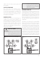
Fig. 6
However, MartinLogan’s unique controlled
dispersion electrostatic transducer inherently
minimizes side wall reflections—a position as
little as two feet from the side walls often proves
adequate. Sometimes, if the system is bright or the
imaging is not to your liking, and the side walls
are very near, try putting curtains or softening
material directly to the edge of each speaker. An
ideal side wall, however, is no side wall at all.
EXPERIMENTATION
Toe-in
Now you can begin to experiment. First begin
by toeing your speakers in towards the listening
area and then facing them straight into the room.
You will notice the tonal balance and imaging
changing. You will notice that as the speakers are
toed-out, the system becomes slightly brighter than

11
when toed-in. This design gives you the flexibility to
compensate for a soft or bright room.
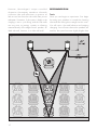
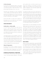
Generally it is found that the ideal listening position
is with the speakers slightly toed-in so that you are
listening to the inner third of the curved transducer
section. A simple, yet effective method to achieve
proper toe involves sitting at the listening position,
holding a flashlight under your chin and pointing
it at each speaker. The reflection of the flashlight
should be within the inner third of the panel (see
figure 7).
Imaging
In their final location, your EM-ESL X’s can
have a stage width somewhat wider than the
speakers themselves. On well recorded music,
the instruments can extend beyond the edges of
each speaker (left and right), yet a vocalist should
appear directly in the middle. The size of the
instruments should be neither too large nor too
small, subject to the intent and results of each
unique audio recording.
Additionally, you should find good clues as to
stage depth. Make sure that the vertical alignment,
distance from the front wall, and toe-in is exactly
the same for both speakers. This will greatly
enhance the quality of your imaging.
Bass Response
Your bass response should neither be one note
nor should it be too heavy. It should extend to
the deepest organ passages and yet be tight
and well defined. Kick-drums should be tight and
percussive—string bass notes should be uniform
and consistent throughout the entirety of the run
without booming or thudding.
Tonal Balance
Voices should be natural and full and cymbals
should be detailed and articulate yet not bright
and piercing, pianos should have a nice transient
characteristic and deep tonal registers. This will give
you clues on how to get closer to these ideal virtues.
FINAL PLACEMENT
After the full break in period, obtaining good wall
treatments, and the proper toe-in angle, begin to
experiment with the distance from the wall behind
the speakers Move your speaker slightly forward
into the room. What happened to the bass
response? What happened to the imaging? If the
imaging is more open and spacious and the bass
response is tightened, that is a superior position.
Move the speakers back six inches from the initial
setup position and again listen to the imaging and
bass response. There will be a position where
you will have pinpoint imaging and good bass
response. That position is the point of the optimal
placement from the front wall.
Now experiment with placing the speakers farther
apart. As the speakers are positioned farther apart,
listen again, not so much for bass response but
for stage width and good pinpoint focusing. Your
ideal listening position and speaker position will
be determined by:
• Tightness and extension of bass response
• Width of the stage
• Pinpoint focusing of imaging
Once you have determined the best of all three
of these considerations, you will have your best
speaker location.
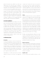
THE EXTRA “TWEAK”
This extra “tweak” may be useful when your
speakers are placed in a dedicated listening room.
Use the following procedure and measurements
for your speakers placement to see what can
happen to your system’s performance. These
formulas will help determine optimum placement
of your speakers to minimize standing waves.

12
1 Distance from the front wall (in front of the
listening position) to the center of the curvilinear
transducer: To determine distance from the front
wall, measure the ceiling height (inches) and
multiply the figure by 0.618 (i.e. ceiling height
(inches) x 0.618 = the distance from the front
wall to the center of the curvilinear transducer).
2 Distance from the side-walls to the center of the
curvilinear transducer: To determine distance
from the side walls, measure the width of
your room in inches and divide by 18. Next,
multiply the quotient by 5 (i.e. room width in
inches / 18 x 5 = the distance from the side-
walls to the center of the curvilinear transducer).
Fig. 7

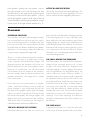
13
YOUR ROOM
This is one of those areas that requires both a little
background to understand and some time and
experimentation to obtain the best performance
from your system.
Your room is actually a component and an important
part of your system. It can dramatically add to, or
subtract from, a great musical experience.
All sound is composed of waves. Each note
has its own wave size, with the lower bass
notes literally encompassing from 10’ feet to as
much as 40’ feet. Your room participates in this
wave experience like a three dimensional pool
with waves reflecting and becoming enhanced
depending on the size of the room and the types
of surfaces in the room. Remember, your audio
system can literally generate all of the information
required to recreate a musical event in time,
space, and tonal balance. Ideally, your room
should not contribute to that information. However,
every room does contribute to the sound to some
degree. Fortunately MartinLogan had designed the
EM-ESL X to minimize these anomalies.
TERMINOLOGY
Standing Waves
The parallel walls in your room will reinforce
certain notes to the point that they will sound louder
than the rest of the audio spectrum and cause “one
note bass”, “boomy bass” or “bloated bass”. For
instance, 100Hz represents a 10 feet wavelength.
Your room will reinforce that specific frequency if
one of the dominant dimensions is 10 feet. Large
objects in the room such as cabinetry or furniture
can help to minimize this potential problem. Some
serious “audiophiles” will literally build a special
room with no parallel walls just to help eliminate
this phenomenon.
Reflective Surfaces (near-field reflections)
The hard surfaces of your room, particularly if close
to your speaker system, will reflect some waves
back into the room over and over again, confusing
the clarity and imaging of your system. The smaller
sound waves are mostly affected here, and occur in
the mid and high frequencies. This is where voice
and frequencies as high as the cymbals occur.
Resonant Surfaces and Objects
All of the surfaces and objects in your room are
subject to the frequencies generated by your
system. Much like an instrument, they will vibrate
and “carry on” in syncopation with the music, and
contribute in a negative way to the music. Ringing,
boominess, and even brightness can occur simply
because they are “singing along” with your music.
Resonant Cavities
Small alcoves or closet type areas in your room can
be chambers that create their own “standing waves”
and can drum their own “one note” sounds.
Clap your hands. Can you hear an instant echo
respond back? You have near-field reflections.
Stomp your foot. Can you hear a “boom”? You
have standing waves or large panel resonances
such as a poorly supported wall. Put your head in a
small cavity area and talk loudly. Hear a booming?
You’ve just experienced a cavity resonance.
RULES OF THUMB
Hard vs. Soft Surfaces
If the front or back wall of your listening room
is soft, it might benefit you to have a hard or
reflective wall in opposition. The ceiling and floor
should follow the same basic guideline as well.
However, the side walls should be roughly the
same in order to deliver a focused image.
room acoustIcs

14
This rule suggests that a little reflection is good.
As a matter of fact, some rooms can be so “over
damped” with carpeting, drapes and sound
absorbers that the music system can sound dull and
lifeless. On the other hand, rooms can be so hard
that the system can sound like a gymnasium with
too much reflection and brightness. The point is
that balance is the optimum environment.
Breakup Objects
Objects with complex shapes, such as
bookshelves, cabinetry and multiple shaped walls
can help break up those sonic gremlins and diffuse
any dominant frequencies.
DIPOLAR SPEAKERS AND YOUR ROOM
MartinLogan electrostatic loudspeakers are known
as dipolar radiators. This means that they produce
sound from both their fronts and their backs.
Consequently, musical information is reflected by
the wall behind them and may arrive, either in or
out of step, with the information produced by the
front of the speaker.
The low frequencies can either be enhanced or
nulled by the position from the front wall. Your
EM-ESL X’s have been designed to be placed two
to three feet from the front wall (the wall in front
of the listening position) to obtain the best results;
however, your room may see things differently. So
listening to the difference of the bass response as a
result of the changes in distance from the front wall
can allow you to get the best combination of depth
of bass and tonal balance.
Now that you know about reflective surfaces and
resonant objects, you can see how the midrange
and high frequencies can be affected. The timing
of the initial wave as it radiates to your ears, and
then the reflected information as it arrives at your
ears later in time, can result in confusion of the
precious timing information that carries the clues
to imaging. Consequently the result is blurred
imaging and excessive brightness. Soft walls,
curtains, wall hangings, or sound dampeners (your
dealer can give you good information here) can
be effective if these negative conditions occur.
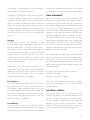
SOLID FOOTING
After living and experimenting with your EM-ESL
X speakers, you may want to expose the ETC
(energy transfer coupler) Spikes (see figure 8).
With the use of these spikes, the EM-ESL X will
become more firmly planted on the floor and,
consequently, bass will tighten and imaging will
become more coherent and detailed. It is best not
to use the spikes, however, until you are secure in
the positioning, as the spikes can damage the floor
if the speaker is moved.
Exposing the Spikes
Remove the rubber bumpers to expose the spikes
(see figure 6). If the speaker does not sit level loosen
one spike until level is achieved. Caution: Make
sure your hands and any cabling are clear of the
spikes. Do not slide speaker as spikes are sharp
and can damage your floor or carpet. Caution:
Walking the speaker may result in a broken spike.
Fig. 8

15
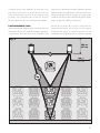
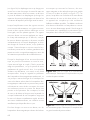
CONTROLLED HORIZONTAL DISPERSION
Your EM-ESL X’s launch a 30 degree horizontal
dispersion pattern. This horizontal dispersion field
gives a choice of good seats for the performance
while minimizing interactions with side walls (see
figure 13). Make sure both speakers stand exactly
at the same vertical angle, otherwise the image
can be skewed or poorly defined. The wave
launch of both speakers is extremely accurate in
both the time and spectral domain. Consequently,
small refined adjustments can result in noticeable
sonic improvements.
CONTROLLED VERTICAL DISPERSION
As you can see from the illustrations, your EM-ESL
X speakers project a controlled dispersion pattern
(see figure 14). Each EM-ESL X is a 34 inch line
source. This vertical dispersion profile minimizes
interactions with the floor and the ceiling.
THREE MAJOR TYPES OF DISPERSION
It is a known fact that as the sound wave becomes
progressively smaller than the transducer producing
it, the dispersion of that wave becomes more and
more narrow, or directional. This fact occurs as
long as the transducer is a flat surface. Large flat
panel speakers exhibit venetian blind effects due
to this phenomenon. This is one reason why many
manufacturers opt for small drivers (i.e. tweeters
and midrange) to approximate what is known as a
point source wave launch.
Historically, most attempts to achieve smooth dis-
persion from large flat panel transducers resulted
in trade-offs. After exhaustive testing of many differ-
ent methods, we conceived an elegantly simple, yet
intensely hand crafted process. By curving the radiat-
ing surface, we create the effect of a horizontal arc.
This allows the engineers at MartinLogan to control the
high frequency dispersion pattern of our transducers.
dIsPersIon InteractIons
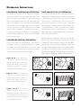
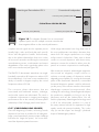
Figure 9–10. As can be seen here,
point source concepts invite a great
deal of room interaction. While deliv-
ering good frequency response to a
large listening audience, imaging is
consequently confused and blurred.
Figure 11–12. Even though they
suffer from “venetian blind” effect,
angled multiple panel speakers can
deliver good imaging, but only to
specific spots in the listening area.
Figure 13–14. A controlled 30
degree cylindrical wave-front, a
MartinLogan exclusive, offers optimal
sound distribution with minimal room
interaction. The result is solid imaging
with a wide listening area.

16
Home tHeater
It had long been the practice of stereo buffs to
connect their television to a stereo system. The
advantage was the use of the larger speakers and
more powerful amplifier of the stereo system. Even
though the sound was greatly improved, it was still
mono and limited by the broadcast signal.
In the late 1970’s and early 1980’s two new
home movie formats became widely available to
the public: VCR and laser disc.
By 1985, both formats had developed into very
high quality audio/video sources. In fact, the sonic
performance of some video formats exceeded
audio-only formats. Now, with theater-quality
sound available at home, the only element missing
was the “surround sound” presentation found in
movie houses.
Fortunately, Dolby and DTS encoded DVD’s
emerged with the same surround sound
information encoded on home releases as the
theatrical release. Additionally, new high-
resolution home-viewing formats such as Blu-ray
as well as high-definition content provided via
cable or satellite have evolved which include multi-
channel encoded audio that is virtually master
tape quality. All that is required to retrieve this
information is a decoder and additional speakers
and amps to reproduce it.
Home theater is a complex purchase and we
recommend that you consult your local MartinLogan
dealer, as they are well versed in this subject.
Each piece of a surround system can be purchased
separately. Take your time and buy quality. No
one has ever complained that the movie was too
real. The following list and descriptions will give
you only a brief outline of the responsibilities and
demands placed on each speaker.
Front Left and Front Right
If these speakers will be the same two used for
your stereo playback, they should be of very high
quality and able to play loudly (over 102 dB) and
reproduce bass below 80 Hz.
Center Channel
This is the most important speaker in a home
theater system, as almost all of the dialogue and
a large portion of the front speaker information is
reproduced by the center channel. It is important
that the center speaker be extremely accurate and
mate well with the front speaker, and that it is
recommended for use as a center speaker. This is
not the place to cut corners.
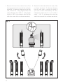
Surround Speakers
We recommend (along with the film industry) that
the surround speakers play down to at least 80
Hz. Surround speakers contain the information that
makes it appear that planes are flying over your
Figure 15. MartinLogan peakers as front, center, and
surround channels, and MartinLogan subwoofers in the
front corners as the 0.1 (effects) channel.

17
head. Some may suggest that this is the place to
save money and purchase small, inexpensive
speakers. If you choose to do so, be prepared
to upgrade in the future as discrete multi-channel
digital encoding is proliferating rapidly and the
demands on surround speakers have increased.
Subwoofer
With any good surround system you will need high-
quality subwoofers (the .1 in a 5.1, 6.1, or 7.1
channel surround system). Most movie soundtracks
contain large amounts of bass information as part of
the special effects. Good subwoofers will provide a
foundation for the rest of the system.
electrostatIc advantages
How can sound be reproduced by something that
you are able to see through? Electrostatic energy
makes this possible.
Where the world of traditional loudspeaker
technology deals with cones, domes, diaphragms
and ribbons that are moved with magnetism, the
world of electrostatic loudspeakers deals with
charged electrons attracting and repelling each other.
To fully understand the electrostatic concept, some
background information will be helpful. Remember
when you learned in a science or physics class
that like charges repel each other and opposite
charges attract each other? Well, this principle is
the foundation of the electrostatic concept.
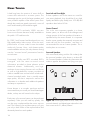
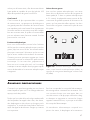
An electrostatic transducer consists of three pieces:
stators, the diaphragm and spacers (see figure
16). The diaphragm is what actually moves to
excite the air and create music. The stator’s job
is to remain stationary, hence the word stator,
and to provide a reference point for the moving
diaphragm. The spacers provide the diaphragm
with a fixed distance in which to move between
the stators.
As your amplifier sends music signals to an
electrostatic speaker, these signals are changed
into two high-voltage signals that are equal in
strength but opposite in polarity. These high
voltage signals are then applied to the stators.
Figure 16. Cut away view of an electrostatic
transducer. Notice the simplicity due to minimal
parts usage.
Figure 17. Cut away view of a typical moving
coil driver. Notice the complexity due to the high
number of parts.

18
martInlogan exclusIves
FULL RANGE OPERATION
Another significant advantage of MartinLogan’s
exclusive transducer technology reveals itself
when you look at examples of other loudspeaker
products on the market today. The EM-ESL X uses
no crossover networks above 400 Hz because
they are not needed. The EM-ESL X consists
of a single, seamless electrostatic membrane
reproducing all frequencies above 400 Hz
simultaneously. How is this possible?
First we must understand that music is not composed
of separate high, mid and low frequency pieces.
In fact, music is comprised of a single complex
waveform with all frequencies interacting
simultaneously.
The electrostatic transducer of the EM-ESL X
essentially acts as an exact opposite of the
microphones used to record the original event. A
microphone, which is a single working element,
transforms acoustic energy into an electrical signal
that can be amplified or preserved by some type
of storage media. The EM-ESL X’s electrostatic
transducer transforms electrical energy from your
amplifier back into acoustical energy.
Due to the limitations of electromagnetic drivers,
no single unit can reproduce the full range
of frequencies. Instead, these drivers must be
designed to operate within a narrow, fixed
bandwidth of the frequency range, and then
combined electrically so that the sum of the parts
equals the total signal. While nice in theory, we
must deal with real-world conditions.
In order to use multiple drivers, a crossover
network is enlisted to attempt a division of the
The resulting electrostatic field, created by the
opposing high voltage on the stators, works
simultaneously with and against the diaphragm,
consequently moving it back and forth, producing
music. This technique is known as push-pull
operation and is a major contributor to the sonic
purity of the electrostatic concept due to its
exceptional linearity and low distortion.
Since the diaphragm of an electrostatic speaker
is uniformly driven over its entire area, it can be
extremely light and flexible. This allows it to be
very responsive to transients, thus perfectly tracing
the music signal. As a result, great delicacy,
nuance and clarity is possible. When you look at
the problems of traditional electromagnetic drivers,
you can easily see why this is so beneficial. The
cones and domes which are used in traditional
electromagnetic drivers cannot be driven uniformly
because of their design. Cones are driven only
at the apex. Domes are driven at their perimeter.
As a result, the rest of the cone or dome is just
“along for the ride”. The very concept of these
drivers requires that the cone or dome be perfectly
rigid, damped and massless. Unfortunately, these
conditions are not available in our world today.
To make these cones and domes move, all
electromagnetic drivers must use voice coils wound
on formers, spider assemblies, and surrounds to
keep the cone or dome in position (see figure 17).
These pieces, when combined with the high mass
of the cone or dome materials used, make it an
extremely complex unit with many weaknesses and
potential for failure. These faults contribute to the
high distortion products found in these drivers and
is a tremendous disadvantage when you are trying
to change motion as quickly and as accurately as
a loudspeaker must (40,000 times per second!).

19
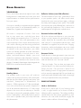
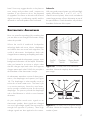
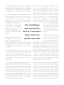
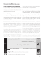
MartinLogan ElectroMotion ESL X Conventional Loudspeaker
crossover point (2,000–5,000 Hz)
crossover point (100–500 Hz)
Critical Zone: 400 Hz–20 kHz
crossover point (400 Hz)
Woofer
EM-
Panel
EXL
Woofer
Midrange
Tweeter
Figure 18. This diagram illustrates how a conventional
speaker system must use multiple crossover networks that
have negative effects on the musical performance.
complex musical signal into the separate pieces
(usually highs, mids, and lows) that each specific
driver was designed to handle. Unfortunately,
due to the phase relationships that occur within
all crossover networks and during the acoustical
recombination process, nonlinearities and severe
degradation of the music signal take place in the
ear’s most critical zone (see figure 18).
The EM-ESL X’s electrostatic transducer can single-
handedly reproduce all frequencies above 400
Hz simultaneously. You have in one transducer the
ability to handle in elegant simplicity the critical
frequencies above 400 Hz.
The crossover phase aberrations that are
associated with traditional tweeter, midrange,
and woofer systems are eliminated. The result is
a dramatic improvement in imaging and staging
performance due to the minutely accurate phase
relationship of the full-range panel wave launch.
CLS™ (CURVILINEAR LINE SOURCE)
Since the beginning of audio, achieving smooth
dispersion has been a problem for all designers.
Large panel transducers present unique challenge
because the larger the panel, the more direc-
tional the dispersion pattern becomes.
Wide range electrostats have long been one of
the most problematic transducers because they
attain their full range capabilities via a large
surface area. It looked as if they were in direct
conflict to smooth dispersion and almost every
attempt to correct this resulted in either poor dis-
persion or a serious compromise in sound quality.
After extensive research, MartinLogan engineers
discovered an elegantly simple solution to
achieve a smooth pattern of dispersion without
degrading sound quality. By curving the horizontal
plane of the electrostatic transducer, a controlled
horizontal dispersion pattern could be achieved,
yet the purity of the almost massless electrostatic
diaphragm remained uncompromised. After
creating this technology, MartinLogan developed
the production capability to bring it out of the
laboratory and into the market place. You will
find this proprietary MartinLogan technology used
in all of our electrostatic products. It is one of
the many reasons behind our reputation for high
quality sound with practical usability. This is also
why you see the unique “see through” cylindrical
shape of MartinLogan products.

20
In the late 1800’s, any loudspeaker was
considered exotic. Today, most of us take the
wonders of sound reproduction for granted.
It was 1880 before Thomas Edison had invented
the first phonograph. This was a horn-loaded
diaphragm that was excited by a playback
stylus. In 1898, Sir Oliver Lodge invented a
cone loudspeaker, which he referred to as a
“bellowing telephone”, that was very similar to
the conventional cone loudspeaker drivers that we
know today. However, Lodge had no intention for
his device to reproduce music because in 1898
there was no way to amplify an electrical signal!
As a result, his speaker had nothing to offer over
the acoustical gramophones of the period. It was
not until 1906 that Dr. Lee DeForrest invented the
triode vacuum tube. Before this, an electrical signal
could not be amplified. The loudspeaker, as we
know it today, should have ensued then, but it did
not. Amazingly, it was almost twenty years before
this would occur.
In 1921, the electrically cut phonograph record
became a reality. This method of recording was
far superior to the mechanically cut record and
possessed almost 30 dB of dynamic range.
The acoustical gramophone couldn’t begin to
reproduce all of the information on this new disc.
As a result, further developments in loudspeakers
were needed to cope with this amazing new
recording medium.
By 1923, the decision to develop a complete
electrostatIc HIstory
XSTAT™ TRANSDUCER
XStat™ transducers incorporate a myriad of
technology and design innovations including
CLS™, MicroPerf, Generation 2 Diaphragms,
ClearSpars™, and Vacuum Bonding.
MICROPERF STATOR
Sleek. Compact. MicroPerf stator technology,
featured in EM-ESL X’s electrostatic transducer,
reveals more open playable area in each panel,
offering increased performance from even more
compact stat panels. It is significant to note that the
electrostatic transducer in the radical new EM-ESL
X loudspeaker supports the bandwidth and
dynamics associated with traditional electrostatic
panels nearly twice its size.
VACUUM BONDING
To achieve the power, precision, and strength of
the electrostatic transducer, two insulated high-
purity carbon steel stators along with a proprietary
plasma bonded diaphragm and ClearSpar™
spacers are fused into a curved geometry with
an aerospace adhesive whose strength exceeds
that of welding. Our proprietary Vacuum Bonding
process guarantees uniform diaphragm tensioning
and extremely precise construction tolerances,
resulting in unequivocal precision, linearity and
efficiency.
AIRFRAME™ TECHNOLOGY
Ultra-rigid extruded aerospace grade aluminum
alloy AirFrame™ technology rigidifies and secures
the electrostatic panel to the woofer cabinet while
at the same time providing sonic and electrical
isolation. Advanced AirFrame™ technology
maximizes the electrostatic panels playable
surface area and dipole dispersion pattern while
minimizing potentially acoustically destructive
intermodulated distortion caused by spurious
vibrations and resonance. The result? Ultimate
imaging capability, low-level detail resolution,
improved efficiency and overall accuracy.
La page charge ...
La page charge ...
La page charge ...
La page charge ...
La page charge ...
La page charge ...
La page charge ...
La page charge ...
La page charge ...
La page charge ...
La page charge ...
La page charge ...
La page charge ...
La page charge ...
La page charge ...
La page charge ...
La page charge ...
La page charge ...
La page charge ...
La page charge ...
La page charge ...
La page charge ...
La page charge ...
La page charge ...
La page charge ...
La page charge ...
La page charge ...
La page charge ...
La page charge ...
La page charge ...
La page charge ...
La page charge ...
La page charge ...
La page charge ...
La page charge ...
La page charge ...
La page charge ...
La page charge ...
La page charge ...
La page charge ...
-
 1
1
-
 2
2
-
 3
3
-
 4
4
-
 5
5
-
 6
6
-
 7
7
-
 8
8
-
 9
9
-
 10
10
-
 11
11
-
 12
12
-
 13
13
-
 14
14
-
 15
15
-
 16
16
-
 17
17
-
 18
18
-
 19
19
-
 20
20
-
 21
21
-
 22
22
-
 23
23
-
 24
24
-
 25
25
-
 26
26
-
 27
27
-
 28
28
-
 29
29
-
 30
30
-
 31
31
-
 32
32
-
 33
33
-
 34
34
-
 35
35
-
 36
36
-
 37
37
-
 38
38
-
 39
39
-
 40
40
-
 41
41
-
 42
42
-
 43
43
-
 44
44
-
 45
45
-
 46
46
-
 47
47
-
 48
48
-
 49
49
-
 50
50
-
 51
51
-
 52
52
-
 53
53
-
 54
54
-
 55
55
-
 56
56
-
 57
57
-
 58
58
-
 59
59
-
 60
60


MartinLogan ElectroMotion ESL X Manuel utilisateur
- Taper
- Manuel utilisateur
dans d''autres langues
Documents connexes
-
 MartinLogan EM-ESL Manuel utilisateur
-
 MartinLogan CLASSIC9WAL Le manuel du propriétaire
-
 MartinLogan Theos Manuel utilisateur
-
 MartinLogan NEOLITH Manuel utilisateur
-
 MartinLogan Classic ESL 9 Manuel utilisateur
-
 MartinLogan ElectroMotion ESL C Manuel utilisateur
-
 MartinLogan Motion 50XT Manuel utilisateur
-
MartinLogan Motion 35XT Manuel utilisateur
-
MartinLogan Motion 60XT Manuel utilisateur
-
 MartinLogan 40 Manuel utilisateur


Autres documents
-
Sony SS-M9ED Manuel utilisateur
-
Telex E-V Five-A Manuel utilisateur
-
 Bowers & Wilkins XT2 Manuel utilisateur
-
Yamaha NS-F901 Le manuel du propriétaire
-
 Pro-Linear PTX55CBE/CBL Le manuel du propriétaire
-
 Bowers & Wilkins Emphasis Le manuel du propriétaire
-
 Bowers & Wilkins DM630 Manuel utilisateur
-
DAVIS HERA 70 frene clair X2 Le manuel du propriétaire
-
 Mosscade HD-C36 Manuel utilisateur
-


