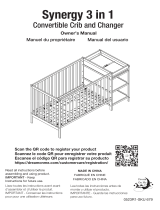
Delta Children Abby Crib N Changer Assembly Instructions
- Catégorie
- Meubles de bébé
- Taper
- Assembly Instructions

Read all instructions
before assembly and use.
KEEP INSTRUCTIONS FOR
FUTURE USE.
Lisez toutes les instructions avant
l’assemblage et l’utilisation.
CONSERVEZ LES INSTRUCTIONS
POUR UN USAGE ULTERIEUR.
Lea todas las instrucciones
antes de ensamblar y usar.
MANTENGA LAS INSTRUCCIONES
PARA SU USO FUTURO.
When contacting Delta Consumer Experience Center please reference the above information. Before contacting
Delta Consumer Experience Center please ensure that the information above matches the information found on the
label on the product, please reference the information found on the product when contacting Delta Consumer
Experience Center.
Lorsque vous contactez le Service client de Delta, veuillez faire référence aux informations ci-dessus. Avant de
contacter le Service client de Delta, veuillez vous assurer que les informations ci-dessus correspondent aux
informations indiquées sur l’étiquette qui se trouve sur le produit; veuillez faire référence aux informations indiquées
sur le produit lorsque vous contactez le Service client de Delta.
Al contactar al servicio al cliente de Delta, entregue la información anteriormente mencionada. Antes de
contactar al servicio de atención al cliente de Delta, asegúrese de que la información anteriormente mencionada
calza con la que aparece en la etiqueta en el producto; al contactar al centro de atención al cliente de Delta,
mencione la información que aparece en el producto.
CONSUMER EXPERIENCE CENTER
Delta Children’s Products Corp |114 West 26th Street New York, NY 10001
(646) 435-8727 | [email protected] | www.DeltaChildren.com
Style #:
Lot:
Date:
___________
___________
___________
C
REV
This product is not intended for institutional or commercial use.
Ce produit ne pas destine a un usage institutionnel ou commercial.
Este producto no esta hecho para uso institucional o comercial.
ADULT ASSEMBLY REQUIRED
Due to the presence of small parts during assembly, keep out
of reach of children until assembly is complete.
L’ASSEMBLAGE DOIT ETRE FAIT
PAR UN ADULTE
A cause de la presence de petites pieces, pendant l’assemblage
gardez hors de portee des enfants jusqu'a ce que celui-ci soit
termine.
DEBE SER ENSAMBLADO
POR UN ADULTO
Debido a la presencia de piezas pequeñas durante el
ensamblaje, mantenga fuera del alcance de los niños hasta que
complete el ensamblaje.
NEED EXTRA HELP?
We make assembly easy with
our tips & tricks video
https://www.deltachildren.com/
pages/instructions
BESOIN D'AIDE SUPPLÉMENTAIRE?
Nous facilitons l'assemblage avec
nos trucs et astuces vidéo
https://www.deltachildren.com/
pages/instructions
¿NECESITA AYUDA EXTRA?
Hacemos el montaje fácil con
nuestros consejos y trucos video
https://www.deltachildren.com/
pages/instructions
June 17, 2020, 40769, R2
©2020 DELTA ENTERPRISE CORP.
ASSEMBLY INSTRUCTIONS • INSTRUCTIONS DE MONTAGE • INSTRUCCIONES DE MONTAJE
Crib N Changer
Lit de bébé et Table à Langer
Cuna y cambiador
La page est en cours de chargement...
La page est en cours de chargement...

CONSEILS POUR FAIRE DORMIR
VOTRE BÉBÉ EN TOUTE SÉCURITÉ
Conseils de l’AAP: Placez toujours votre bébé
sur le dos pour dormir. Consultez votre médecin.
Visitez Deltachildren.Com/Pages/Crib-Safety-Tips pour plus d’information
NE déposez aucun objet
dans le Lit de Bébé
Votre bébé doit dormir
sur un matelas ferme.
Des oreillers et
couvertures ont parfois
été responsables
d’étouffements de
nourrissons. N’en utilisez
JAMAIS dans un lit de
bébé.
Les lits d’adultes ne sont
pas un lieu sûr pour les
bébés: NE dormez
JAMAIS ensemble.
NE placez JAMAIS le Lit de
Bébé à proximité d’une
fenêtre ou de tentures.
L’endroit le plus sûr pour
faire dormir votre bébé,
c’est dans un Lit de
Bébé approuvé par
JPMA.
Des pièces manquantes
ou cassées?APPELEZ Delta
Children Consumer Care.
Lisez tous les
avertissements et
respectez toutes les
consignes de sécurité.
ASSEMBLY INSTRUCTIONS • INSTRUCTIONS DE MONTAGE • INSTRUCCIONES DE MONTAJEASSEMBLY INSTRUCTIONS • INSTRUCTIONS DE MONTAGE • INSTRUCCIONES DE MONTAJEASSEMBLY INSTRUCTIONS • INSTRUCTIONS DE MONTAGE • INSTRUCCIONES DE MONTAJE
4

LE RENVERSEMENT DU MEUBLE PEUT ENTRAÎNER DES
BLESSURES GRAVES OU MORTELLES.
NE déposez PAS de
postes de télévision ou
d’autres objets lourds sur
des meubles de
chambre à coucher ou
de chambre d’enfants.
Utilisez TOUJOURS les
dispositifs de
non-renversement
fournis.
NE laissez JAMAIS les
enfants monter sur ou se
suspendre aux tiroirs,
portes et ou tablettes.
Placez les objets les
plus lourds dans les
tiroirs du bas.
N’OUVREZ JAMAIS plus
d’un tiroir en même
temps
NE laissez PAS les tiroirs
ouverts lorsque vous
ne les utilisez pas.
Visitez Deltachildren.Com/Pages/Leaders-In-Safety pour plus d’information
ASSEMBLY INSTRUCTIONS • INSTRUCTIONS DE MONTAGE • INSTRUCCIONES DE MONTAJEASSEMBLY INSTRUCTIONS • INSTRUCTIONS DE MONTAGE • INSTRUCCIONES DE MONTAJE
Lisez tous les
avertissements et
respectez toutes les
consignes de sécurité.
Des pièces manquantes
ou cassées?APPELEZ Delta
Children Consumer Care.
CONSEILS DE SÉCURITÉ RELATIFS
AUX MEUBLES
5
La page est en cours de chargement...
La page est en cours de chargement...
La page est en cours de chargement...

ASSEMBLY INSTRUCTIONS • INSTRUCTIONS DE MONTAGE • INSTRUCCIONES DE MONTAJEASSEMBLY INSTRUCTIONS • INSTRUCTIONS DE MONTAGE • INSTRUCCIONES DE MONTAJEASSEMBLY INSTRUCTIONS • INSTRUCTIONS DE MONTAGE • INSTRUCCIONES DE MONTAJE
DELTA CHILDREN
@deltachildren
SUIVEZ NOUS POUR AVOIR PLUS DE CHANCES DE GAGNER /
SÍGANOS PARA TENER MAS CHANCES DE GANAR
SCANNEZ ICI / ESCANEE AQUÍ
Pour plus d'informations et
pour voir tous nos produits
Para más información y para
ver todos nuestros productos
ÉCONOMISEZ BEAUCOUP AVEC
AHORRE MUCHO CON
Visitez Deltachilren.com Pour Commencer Vos Achats
Visita Deltachilren.com Para Comenzar A Comprar
FAMILLE DELTA
Bienvenue dans la
Voici Notre Cadeau Pour Vous
Votre Prochain Achat Chez
*Subject to Change
*Exclusions Apply
*Des exclusions s’appliquent
*Sujet à changement
Aquí Está Nuestro Regalo Para Usted
FAMILIA DELTA
Bienvenido a la
Su Próxima Compra En
DeltaChildren.com
DELTA10
UTILISEZ LE CODE:
UTILICE EL CÓDIGO:
ECRIVEZ UN COMMENTAIRE CLIENT pour ce produit sur le site web du magasin où il a été acheté
CALIFIQUE EL PRODUCTO en la página web de la tienda donde haya sido comprado
1
FAITES UNE CAPTURE D’ECRAN de votre commentaire client et mettez la en ligne sur www.DeltaChildren.com/Review
HAGA UNA CAPTURA DE PANTALLA de su calificación y cárguela a la pagina www.DeltaChildren.com/Review
2
C’EST AUSSI SIMPLE QUE ÇA! Dès que c’est fait vous serez instantanément INSCRIT POUR GAGNER 2500$
ES ASÍ DE FÁCIL! En cuanto lo envíe ya estará instantáneamente PARTICIPANDO PARA GANAR $2.500
3
REGLEMENT DE PARTICIPATION / REGLAS PARA PARTICIPAR
LAISSEZ UN COMMENTAIRE CLIENT POUR GAGNER $2500
CALIFIQUE EL PRODUCTO PARA GANAR $2500
9

ASSEMBLY INSTRUCTIONS • INSTRUCTIONS DE MONTAGE • INSTRUCCIONES DE MONTAJE
10
PARTS: MAKE SURE THAT ALL PRE-ASSEMBLED PARTS ARE TIGHT
PIÈCES : VÉRIFIEZ QUE TOUTES LES PIÈCES PRÉ-MONTÉES SONT BIEN SERRÉES.
PIEZAS: ASEGÚRESE DE QUE TODAS LAS PIEZAS PRE-ENSAMBLADAS ESTÁN BIEN APRETADAS.
ASSEMBLY INSTRUCTIONS • INSTRUCTIONS DE MONTAGE • INSTRUCCIONES DE MONTAJE
A. Common Side x 1
Côté commun x 1
Lado común x 1
40766
B. Changer End x 1
Extrémité de la table à langer x 1
Extremo del cambiador x 1
40872
C. Changer Top Rail x 2
Traverse supérieure de la table à langer x 2
Barras superiores del cambiador x 2
26451
D. Changer Surface Rail x 2
Barrière de la surface de la table à langer x 2
Barra de la superficie del cambiador x 2
26452
E. Changer Middle Shelf Rail x 2
Traverse de l’étagère centrale de la table à langer x 2
Barra del estante central del cambiador x 2
26453
H. Changer Back Bottom Rail x 1
Traverse arrière inférieure de la table à langer x 1
Barra trasera inferior del cambiador x 1
26457
F. Changer Front Middle Rail x 1
Traverse centrale frontale de la table à langer x 1
Barra central frontal inferior del cambiador x 1
26454
G. Changer Front Bottom Rail x 1
Traverse frontale inférieure de la table à langer x 1
Barra frontal inferior del cambiador x 1
26455
J. Changer Center Top Rail x 1
Traverse centrale supérieure de la table à langer x 1
Barra central superior del cambiador x 1
26456
K. Changer Center Bottom Rail x 1
Traverse centrale inférieure de la table à langer x 1
Barra central inferior del cambiador x 1
26458

ASSEMBLY INSTRUCTIONS • INSTRUCTIONS DE MONTAGE • INSTRUCCIONES DE MONTAJE
11
ASSEMBLY INSTRUCTIONS • INSTRUCTIONS DE MONTAGE • INSTRUCCIONES DE MONTAJE
M. Changer Middle Front Shelf x 1
Étagère centrale frontale de la table à langer x 1
Estante central del frente del cambiador x 1
26447
N. Changer Bottom Shelf x 1
Étagère inférieure de la table à langer x 1
Estante del fondo del cambiador x 1
26449
L. Changer Middle Back Shelf x 1
Étagère centrale arrière de la table à langer x 1
Estante central trasero del cambiador x 1
26448
R. Changer Surface with Strap x 1
Surface de la table à langer avec sangle x 1
Superficie del cambiador con correa x 1
26446
P. Changer Center Panel x 1
Panneau central de la table à langer x 1
Panel central del cambiador x 1
26450
S. Changer Pad x 1
Matelas à langer x 1
Almohadilla para cambiador x 1
25083
U. Crib Front Rail x 1
Barrière avant du lit de bébé x 1
Barandilla frontal de la cuna x 1
26441
W. Crib Top Back Rail x 1
traverse supérieure arrière du lit de bébé x 1
barandilla posterior superior x 1
26037
X. Crib Back Rail x 1
Barrière arrière du lit de bébé x 1
Barandilla posterior de la cuna x 1
26027
V. Stabilizer Bar x 1
Barre stabilisatrice x 1
Barra estabilizadora x 1
26024
T. Left Crib Side x 1
Côté gauche du lit de bébé x 1
Costado izquierdo de la cuna x 1
40765

Pouch attached to mattress suport- keep instructions
in this pouch after assembly. Warnings related to the
safe use ofthis crib are printed on the pouch.
Pochette fixée au support du matelas - une fois le
montage terminé, conserver les instructions dans
cette pochette. Les avertissements concernant
l'utilisation sécuritaire de la couchette sont imprimés
sur cette pochette.
Funda adjunta al colchón Soporte: guarde las
instrucciones en esta funda después de armar. Las
advertencies Relacionadas con el uso seguro de
esta cuna están impresas en la funda.
ASSEMBLY INSTRUCTIONS • INSTRUCTIONS DE MONTAGE • INSTRUCCIONES DE MONTAJE
12
ASSEMBLY INSTRUCTIONS • INSTRUCTIONS DE MONTAGE • INSTRUCCIONES DE MONTAJE
DD. Mattress Support x 1
Support du matelas x 1
Soporte del Colchón x 1
24242
BB. Drawer Right Side x 2
Panneau droit du tiroir x 2
Lado derecho de la gaveta x 2
40768
AA. Drawer Left Side x 2
Panneau gauche du tiroir x 2
Lado izquierdo de la gaveta x 2
40767
Y. Drawer Front x 2
Panneau avant du tiroir x 2
Panel frontal de la gaveta x 2
29056
Z. Drawer Back x 2
Panneau arrière du tiroir x 2
Panel posterior de la gaveta x 2
26460
CC. Drawer Bottom Panel x 2
Panneau inférieur du tiroir x 2
Panel inferior de la gaveta x 2
26463
EE. Left Back Post x 1
Montant arrière gauche x 1
Poste posterior izquierdo x 1
26052
FF. Left Front Post x 1
Montant avant gauche x 1
Poste frontal izquierdo x 1
26442

No drills necessary. Do not use power screwdriver.
Flat Head Screwdriver (not supplied)
Aucun forage n’est nécessaire. Ne pas utiliser de tournevis
électrique. Tournevis à tête plate (non fourni)
No hace falta taladrar No utilice destornilladores eléctricos
Destornillador plano (no suministrado)
ASSEMBLY INSTRUCTIONS • INSTRUCTIONS DE MONTAGE • INSTRUCCIONES DE MONTAJE
13
Parts: Hardware kits part#26464
Pièces: L'ensemble de quincaillerie - pièce n°26464
Piezas: El kit de herramientas - Pieza #26464
ASSEMBLY INSTRUCTIONS • INSTRUCTIONS DE MONTAGE • INSTRUCCIONES DE MONTAJE
M4 Allen Wrench (Supplied)
clé hexagonale M4 (Fournie)
Llave Allen M4 (se Incluye)
1177
TT. 25 mm Screw x 8
Vis de 25 mm x 8
Tornillo de 25 mm x 8
5495
UU. 40 mm Screw x 8
Vis de 40 mm x 8
Tornillo de 40 mm x 8
5513
WW. Plastic Barrel Nut x 8
écrous à portée cylindrique en plastique x 8
Tuerca cilíndrica plástica x 8
5497
GG. Knob x 2
Bouton x 2
Perilla x 2
26440
JJ. M6 x 80 mm Bolt x 18
Boulon M6 x 80 mm x 18
Perno M6 x 80mm x 18
5473
KK. M6 x 60 mm Bolt x 4
Boulon M6 x 60 mm x 4
Perno M6 x 60mm x 4
5469
LL. M6 x 55 mm Bolt x 4
Boulon M6 x 55 mm x 4
Perno M6 x 55mm x 4
5468
MM. M6 x 40 mm Bolt x 3
Boulon M6 x 40 mm x 3
Perno M6 x 40mm x 3
5465
PP. M6 x 18 mm Bolt x 4
Boulon M6 x 18 mm x 4
Perno M6 x 18mm x 4
5763
RR. Φ4x30 mm Metal Pin x 16
chevilles de metal Φ4 x 30 mm x 16
Φ4x30 mm Clavija metálica x 16
5493
HH.Knob Bolt x 2
Vis de Bouton x 2
Tornillo para Perilla x 2
SS. M6x17mm Barrel Nut x 22
Écrous À Portée Cylindrique M6x17 mm x 22
Tuerca Cilíndrica M6x17mm x 22
5479
NN. M6 x 30 mm Bolt x 2
Boulon M6 x 30 mm x 2
Perno M6 x 30mm x 2
5463
Phillips Screwdriver
Tournevis’Phillips’
Destornillardor’Phillips’

ASSEMBLY INSTRUCTIONS • INSTRUCTIONS DE MONTAGE • INSTRUCCIONES DE MONTAJEASSEMBLY INSTRUCTIONS • INSTRUCTIONS DE MONTAGE • INSTRUCCIONES DE MONTAJE
14
Parts and tools required to complete step
Pièces et outils nécessaires au montage
Piezas y herramientas necesarias para completar este paso
Section 1: Changing Table Assembly, Step 1
Section 1 : Montage de la table à langer, Étape 1
Sección 1: Armado del cambiador, Paso 1
M4 Allen Wrench (included)
Clé Allen M4 (inclus)
Llave Allen M4 (incluido)
RR. Φ4x30 mm Metal Pin x 6
chevilles de metal Φ4 x 30 mm x 6
Φ4x30 mm Clavija metálica x 6
SS. M6x17mm Barrel Nut x 5
Écrous À Portée Cylindrique M6x17 mm x 5
Tuerca Cilíndrica M6x17mm x 5
A. Common Side x 1
Côté commun x 1
Lado común x 1
C. Changer Top Rail x 2
Traverse supérieure de la table à langer x 2
Barandilla superior del cambiador x 2
JJ. M6 x 80 mm Bolt x 4
Boulon M6 x 80 mm x 4
Perno M6 x 80mm x 4
KK. M6 x 60 mm Bolt x 2
Boulon M6 x 60 mm x 2
Perno M6 x 60mm x 2
LL. M6 x 55 mm Bolt x 1
Boulon M6 x 55 mm x 1
Perno M6 x 55mm x 1
NN. M6 x 30 mm Bolt x 1
Boulon M6 x 30 mm x 1
Perno M6 x 30mm x 1
E. Changer Middle Shelf Rail x 2
Traverse de l’étagère centrale de la table à langer x 2
Barra del estante central del cambiador x 2
H. Changer Back Bottom Rail x 1
Traverse arrière inférieure de la table à langer x 1
Barra trasera inferior del cambiador x 1
G. Changer Front Bottom Rail x 1
Traverse frontale inférieure de la table à langer x 1
Barra frontal inferior del cambiador x 1
J. Changer Center Top Rail x 1
Traverse centrale supérieure de la table à langer x 1
Barra central superior del cambiador x 1
K. Changer Center Bottom Rail x 1
Traverse centrale inférieure de la table à langer x 1
Barra central inferior del cambiador x 1

15
ASSEMBLY INSTRUCTIONS • INSTRUCTIONS DE MONTAGE • INSTRUCCIONES DE MONTAJEASSEMBLY INSTRUCTIONS • INSTRUCTIONS DE MONTAGE • INSTRUCCIONES DE MONTAJE
C
A
J
C
K
G
H
E
E
RR
JJ
SS
SS
RR
KK
RR
JJ
SS
RR
SS
JJ
KK
RR
RR
JJ
SS
LL
NN
Attach (2) Changer Top Rails (Part C), (2) Changer Middle Shelf Rails (Part E), (1) Changer Front Bottom Rail (Part G), (1) Changer
Back Bottom Rail (Part H), (1) Changer Center Top Rail (Part J) and (1) Changer Center Bottom Rail (Part K) to the Common Side
(Part A) using (6) Φ4x30 mm Metal Pins (Part RR), (1) M6 x 30 mm Bolt (Part NN), (1) M6 x 55 mm Bolt (Part LL), (2) M6 x 60 mm Bolts
(Part KK), (4) M6 x 80 mm Bolt (Part JJ) and (5) M6 x 17 mm Barrel Nuts (Part SS). Tighten with the M4 Allen Wrench. Use the Flat
Head Screwdriver to hold the Barrel Nut in the proper alignment.
Fixez (2) traverses supérieures de la table à langer (pièce C), (2) Traverses de l’étagère centrale de la table à langer (pièce E),
(1) traverse frontale inférieure de la table à langer (pièce G), (1) traverse arrière inférieure de la table à langer (pièce H), (1)
traverse centrale supérieure de la table à langer (pièce J), et (1) traverse centrale inférieure de la table à langer (pièce K) au
côté commun (pièce A) à l’aide de (6) chevilles métalliques Φ4x30 mm (pièce RR), (1) boulon M6 x 30mm (pièce NN), (1) boulon
M6 x 55mm (pièce LL), (2) boulons M6 x 60mm (pièce KK), (4) boulons M6 x 80mm (pièce JJ) et (5) écrous à portée cylindrique
M6 x 17mm (pièce SS). Serrez avec la clé Allen M4. Utilisez le tournevis à tête plate pour tenir l’écrou à portée cylindrique
proprement aligné.
Unir (2) barras superiores del cambiador (pieza C), (2) barras del estnate central del cambiador (pieza E), 1 barra frontal inferior
del cambiador (pieza G), (1) barra trasera inferior del cambiador (pieza H), (1) barra central superior del cambiador (pieza J) y
(1) barra central inferior del cambiador (pieza K) al lado común (pieza A) utilizando (6) clavijas metálicas de Φ4x30 mm (pieza
RR), (1) perno M6 x 30 mm (pieza NN), (1) perno M6 x 55 mm (pieza LL), (2) pernos M6 x 60 mm (pieza KK), (4) pernos M6 x 80 mm
(pieza JJ) y (5) tuercas cilíndricas M6 x 17 mm (pieza SS). Apretar con la llave Allen M4. Utilice el destornillador de cabeza plana
para mantener la tuerca cilíndrica debidamente alineada.

ASSEMBLY INSTRUCTIONS • INSTRUCTIONS DE MONTAGE • INSTRUCCIONES DE MONTAJEASSEMBLY INSTRUCTIONS • INSTRUCTIONS DE MONTAGE • INSTRUCCIONES DE MONTAJE
16
Parts and tools required to complete step
Pièces et outils nécessaires au montage
Piezas y herramientas necesarias para completar este paso
Section 1: Changing Table Assembly, Step 2
Section 1 : Montage de la table à langer, Étape 2
Sección 1: Armado del cambiador, Paso 2
From Step 1
À partir de l’étape 1
Desde el paso 1
R. Changer Surface with Strap x 1
Surface de la table à langer avec sangle x 1
Superficie del cambiador con correa x 1
D. Changer Surface Rail x 2
Barrière de la surface de la table à langer x 2
Barra de la superficie del cambiador x 2
F. Changer Front Middle Rail x 1
Traverse centrale frontale de la table à langer x 1
Barra central frontal inferior del cambiador x 1
Lay Common Side (Part A) on its side and loosely insert (2) Changer Surface Rails (Part D) and
(1) Changer Front Middle Rail (Part F) as shown. Slide Changer Surface with Strap (Part R) into
Changer Surface Rails (Part D) grooves as shown.
Posez le côté commun (pièce A) sur son côté et insérez sans serrer (2) barrières de la surface
de la table à langer (pièce D) et (1) traverse centrale frontale de la table à langer (pièce F)
comme illustré. Glissez la surface avec sangle de la table à langer (pièce R) dans les rainures
des barrières de la surface de la table à langer (pièce D) comme illustré.
Colocar el lado común (pieza A) en su lado e insertar holgadamente (2) barras de la
superficie del cambiador (pieza D) y (1) barra central frontal inferior del cambiador
(pieza F) como se muestra. Deslizar la superficie del cambiador con correa (pieza R) en las
ranuras de los barrases de la superficie del cambiador (pieza D) como se muestra.
La page est en cours de chargement...

ASSEMBLY INSTRUCTIONS • INSTRUCTIONS DE MONTAGE • INSTRUCCIONES DE MONTAJEASSEMBLY INSTRUCTIONS • INSTRUCTIONS DE MONTAGE • INSTRUCCIONES DE MONTAJE
18
Parts and tools required to complete step
Pièces et outils nécessaires au montage
Piezas y herramientas necesarias para completar este paso
Section 1: Changing Table Assembly, Step 3
Section 1 : Montage de la table à langer, Étape 3
Sección 1: Armado del cambiador, Paso 3
From Step 2
À partir de l’étape 2
Desde el paso 2
M. Changer Middle Front Shelf x 1
Étagère centrale frontale de la table à langer x 1
Estante central del frente del cambiador x 1
N. Changer Bottom Shelf x 1
Étagère inférieure de la table à langer x 1
Estante del fondo del cambiador x 1
L. Changer Middle Back Shelf x 1
Étagère centrale arrière de la table à langer x 1
Estante central trasero del cambiador x 1
P. Changer Center Panel x 1
Panneau central de la table à langer x 1
Panel central del cambiador x 1
Slide Changer Center Panel (Part P) into Changer Surface with Strap (Part R) and Changer
Center Bottom Rail (Part K) grooves as shown.
Slide Changer Middle Front Shelf (Part M) into Changer Middle Shelf Rail (Part E) and Changer
Center Top Rail (Part J) grooves as shown.
Slide Changer Middle Back Shelf (Part L) into Changer Middle Shelf Rail (Part E) and Changer
Center Top Rail (Part J) grooves as shown.
Slide Changer Bottom Shelf (Part N) into Changer Center Bottom Rail (Part K) and Changer
Back Bottom Rail (Part H) grooves as shown.
Glissez le panneau central de la table à langer (pièce P) dans la surface avec sangle de la
table à langer (pièce R) et les rainures de la barrière centrale inférieure de la table à langer
(pièce K) comme illustré.
Glissez l’étagère centrale frontale de la table à langer (pièce M) dans le rail central de
l’étagère (pièce E) et les rainures du rail supérieur central de la table à langer (pièce J)
comme illustré.
Glissez l’étagère centrale arrière de la table à langer (pièce L) dans le rail central de la table
à langer (pièce E) et les rainures du rail central supérieur de la table à langer (pièce J)
comme illustré.
Glissez l’étagère inférieure de la table à langer (pièce N) dans le rail central inférieur de la
table à langer (pièce K) et les rainures du rail arrière inférieur (pièce H) comme illustré.
La page est en cours de chargement...

ASSEMBLY INSTRUCTIONS • INSTRUCTIONS DE MONTAGE • INSTRUCCIONES DE MONTAJEASSEMBLY INSTRUCTIONS • INSTRUCTIONS DE MONTAGE • INSTRUCCIONES DE MONTAJE
20
Parts and tools required to complete step
Pièces et outils nécessaires au montage
Piezas y herramientas necesarias para completar este paso
Section 1: Changing Table Assembly, Step 4
Section 1 : Montage de la table à langer, Étape 4
Sección 1: Armado del cambiador, Paso 4
Attach Changer End (Part B) to the assembly from step 3 using (6) Φ4x30 mm Metal Pins (Part
RR), (1) M6 x 30 mm Bolt (Part NN), (1) M6 x 55 mm Bolt (Part LL), (2) M6 x 60 mm Bolt (Part KK),
(4) M6 x 80 mm Bolt (Part JJ) and (5) M6 x 17 mm Barrel Nuts (Part SS). Tighten with the M4
Allen Wrench. Use the Flat Head Screwdriver to hold the Barrel Nut in the proper alignment.
Note: Before assembly, Carefully align all panels, tabs and pins with the holes and slots in the
Changer End (Part B).
Fixez l’extrémité de la table à langer (pièce B) à l’ensemble monté à l’étape 3 à l’aide de (6)
chevilles en métal Φ4 x 30 mm (pièce RR), de (1) boulon M6 x 30 mm (pièce NN), de (1)
boulon M6 x 55 mm (pièce LL), de (2) boulons M6 x 60 mm (pièce KK), de (4) boulons M6 x 80
mm (pièce JJ) et de (5) écrous à portée cylindrique M6 x 17 mm (Pièce SS). Serrez à l’aide de
la clé Allen M4. Utilisez le tournevis à tête plate pour maintenir les écrous à portée cylindrique
dans l’alignement approprié.
Remarque: Avant le montage, alignez avec soin tous les panneaux, languettes et chevilles
sur les trous et les fentes qui se trouvent sur l’extrémité de la table à langer (pièce B).
M4 Allen Wrench (included)
Clé Allen M4 (inclus)
Llave Allen M4 (incluido)
RR. Φ4x30 mm Metal Pin x 6
chevilles de metal Φ4 x 30 mm x 6
Φ4x30 mm Clavija metálica x 6
SS. M6x17mm Barrel Nut x 5
Écrous À Portée Cylindrique M6x17 mm x 5
Tuerca Cilíndrica M6x17mm x 5
From Step 3
À partir de l’étape 3
Desde el paso 3
B. Changer End x 1
Extrémité de la table à langer x 1
Extremo del cambiador x 1
JJ. M6 x 80 mm Bolt x 4
Boulon M6 x 80 mm x 4
Perno M6 x 80mm x 4
KK. M6 x 60 mm Bolt x 2
Boulon M6 x 60 mm x 2
Perno M6 x 60mm x 2
LL. M6 x 55 mm Bolt x 1
Boulon M6 x 55 mm x 1
Perno M6 x 55mm x 1
NN. M6 x 30 mm Bolt x 1
Boulon M6 x 30 mm x 1
Perno M6 x 30mm x 1
La page est en cours de chargement...

ASSEMBLY INSTRUCTIONS • INSTRUCTIONS DE MONTAGE • INSTRUCCIONES DE MONTAJEASSEMBLY INSTRUCTIONS • INSTRUCTIONS DE MONTAGE • INSTRUCCIONES DE MONTAJE
22
Parts and tools required to complete step
Pièces et outils nécessaires au montage
Piezas y herramientas necesarias para completar este paso
Attach (1) Left Back Post (Part EE) to (1) Left Crib Side (Part T) using (3) M6 x 40mm Bolts (Part
MM), (2) M6 x 55mm Bolts (Part LL) and (2) M6 x17 mm Barrel Nuts (Part SS). Tighten with the M4
Allen Wrench. Use the Flat Head Screwdriver to hold the Barrel Nut in the proper alignment.
Fixez (1) montant arrière gauche (pièce EE) à (1) côté gauche du lit de bébé (pièce T) à l’aide
de (3) boulons M6 x 40 mm (pièce MM), (2) boulons M6 x 55 mm (pièce LL) et de (2) écrous à
portée cylindrique M6 x17 mm (pièce SS). Serrez à l’aide de la clé hexagonale M4. Utilisez le
tournevis à tête plate pour maintenir les écrous à portée cylindrique dans l’alignement
approprié.
Fije (1) poste posterior izquierdo (Pieza EE) a (1) costado izquierdo de la cuna (Pieza T)
utilizando (3) pernos M6 x 40 mm (Pieza MM), (2) pernos M6 x 55 mm (Pieza LL) y (2) tuercas de
barril M6 x 17 mm (Pieza SS). Apriete todos los pernos utilizando la Llave Allen M4. Utilice el
destornillador de cabeza plana para sostener la tuerca de barril en la alineación adecuada.
Section 2: Crib Assembly, Step 1
Section 2: Montage du lit de bébé, Étape 1
Sección 2: Montaje de la cuna, Paso 1
M4 Allen Wrench (Supplied)
clé hexagonale M4 (Fournie)
Llave Allen M4 (se Incluye)
SS. M6x17mm Barrel Nut x 2
Écrous À Portée Cylindrique M6x17 mm x 2
Tuerca Cilíndrica M6x17mm x 2
T. Left Crib Side x 1
Côté gauche du lit de bébé x 1
Costado izquierdo de la cuna x 1
EE. Left Back Post x 1
Montant arrière gauche x 1
Poste posterior izquierdo x 1
FF. Left Front Post x 1
Montant avant gauche x 1
Poste frontal izquierdo x 1
LL. M6 x 55 mm Bolt x 2
Boulon M6 x 55 mm x 2
Perno M6 x 55mm x 2
MM. M6 x 40 mm Bolt x 3
Boulon M6 x 40 mm x 3
Perno M6 x 40mm x 3
La page est en cours de chargement...

ASSEMBLY INSTRUCTIONS • INSTRUCTIONS DE MONTAGE • INSTRUCCIONES DE MONTAJEASSEMBLY INSTRUCTIONS • INSTRUCTIONS DE MONTAGE • INSTRUCCIONES DE MONTAJE
24
Parts and tools required to complete step
Pièces et outils nécessaires au montage
Piezas y herramientas necesarias para completar este paso
1. Attach (1) Crib Front Rail (Part U) to (1) Stabilizer Bar (Part V) using (2) Φ4x30 mm Metal Pins (Part RR).
2. Attach (1) Left Crib Side (
From Section 2: Step 1
), (1) Crib Front Rail (Part U) and (1) Stabilizer Bar (Part
V) to the assembly from section 1 step 4 using (4) M6 x 80 mm Bolts (Part JJ) and (4) M6 x 17mm Barrel
Nuts (Part SS). Tighten with the M4 Allen Wrench. Use the Flat Head Screwdriver to hold the Barrel Nut in
the proper alignment.
1. Fixer (1) barrière avant du lit de bébé (pièce U) à (1) barre stabilisatrice (pièce V) à l’aide de (2)
chevilles en métal Φ 4 x 30 mm (pièce RR).
2. Fixez (1) Côté gauche du lit de bébé (
À partir de Section 2: l’étape 1
), (1) barrière avant du lit de
bébé (pièce U) et (1) barre stabilisatrice (pièce V) à l’ensemble monté à la section 1 de l’étape 4 à
l’aide de (4) boulons M6 x 80 mm (pièce JJ) et de (4) écrous à portée cylindrique M6 x 17 mm (pièce
SS). Serrez à l’aide de la clé Allen M4. Utilisez le tournevis à tête plate pour maintenir les écrous à portée
cylindrique dans l’alignement approprié.
1. Fije (1) barandilla frontal de la cuna (Pieza U) a (1) barra estabilizadora (Pieza V) utilizando (2)
pasadores metálicos Φ4x30 mm (Pieza RR).
2. Fije (1) Costado izquierdo de la cuna (
Desde el Sección 2: paso 1
), (1) barandilla frontal de la cuna
(Pieza U) y (1) barra estabilizadora (Pieza V) al conjunto de piezas de la sección 1, paso 4, utilizando (4)
pernos M6 x 80 mm (Pieza JJ) y (4) Tuercas cilíndrica M6 x 17 mm (Pieza SS). Apriete todos los pernos
utilizando la Llave Allen M4. Utilice el destornillador de cabeza plana para sostener la tuerca cilíndrica
en la alineación adecuada.
Section 2: Crib Assembly, Step 2
Section 2: Montage du lit de bébé, Étape 2
Sección 2: Montaje de la cuna, Paso 2
RR. Φ4x30 mm Metal Pin x 2
chevilles de metal Φ4 x 30 mm x 2
Φ4x30 mm Clavija metálica x 2
From Section 1: Step 4
À partir de Section 1: l’étape 4
Desde el Sección 1: paso 4
Left Crib Side (
From Section 2: Step 1
)
Côté gauche du lit de bébé (
À partir de Section 2: l’étape 1
)
Costado izquierdo de la cuna (
Desde el Sección 2: paso 1
)
U. Crib Front Rail x 1
Barrière avant du lit de bébé x 1
Barandilla frontal de la cuna x 1
M4 Allen Wrench (included)
Clé Allen M4 (inclus)
Llave Allen M4 (incluido)
SS. M6x17mm Barrel Nut x 6
Écrous À Portée Cylindrique M6x17 mm x 6
Tuerca Cilíndrica M6x17mm x 6
JJ. M6 x 80 mm Bolt x 6
Boulon M6 x 80 mm x 6
Perno M6 x 80mm x 6
V. Stabilizer Bar x 1
Barre stabilisatrice x 1
Barra estabilizadora x 1

25
ASSEMBLY INSTRUCTIONS • INSTRUCTIONS DE MONTAGE • INSTRUCCIONES DE MONTAJEASSEMBLY INSTRUCTIONS • INSTRUCTIONS DE MONTAGE • INSTRUCCIONES DE MONTAJE
U
V
U
U
V
RR
RR
JJ
BACK!
Both ends
Deux extrémités
Ambos extremos
Both ends
Deux extrémités
Ambos extremos
JJ
SS
JJ
SS
JJ
SS
SS
JJ
SS
JJ

M4 Allen Wrench (Supplied)
clé hexagonale M4 (Fournie)
Llave Allen M4 (se Incluye)
PP. M6 x 18 mm Bolt x 4
Boulon M6x18 mm x 4
Perno M6x18mm x 4
ASSEMBLY INSTRUCTIONS • INSTRUCTIONS DE MONTAGE • INSTRUCCIONES DE MONTAJEASSEMBLY INSTRUCTIONS • INSTRUCTIONS DE MONTAGE • INSTRUCCIONES DE MONTAJE
26
Section 2: Crib Assembly, Step 3
Section 2: Montage du lit de bébé, Étape 3
Sección 2: Montaje de la cuna, Paso 3
Parts and tools required to complete step
Pièces et outils nécessaires au montage
Piezas y herramientas necesarias para completar este paso
Attach the Mattress Support (Part DD) in all corners using (1) M6x18 mm Bolt (Part PP) in each
corner.Tighten with the M4 Allen Wrench.
The WARNINGS printed on the pouch attached to the mattress support must face up, the
springs must face up. This crib has (3) adjustment positions, use the highest only for newborns,
move the mattress down as the child grows.
Fixer le support du matelas (Pièce DD) dans tous les coins à l'aide d' (1) boulon M6 x 18 mm
(Pièce PP) dans chaque coin. Serrez à l'aide de la clé hexagonale M4.
Les AVERTISSEMENTS qui se trouvent sur la pochette fixée au support du matelas doivent être
tournés vers le haut, les ressorts doivent être tournés vers le haut. La couchette possède (3)
positions d'ajustement, la plus haute ne doit servir que pour les nouveaux-nés. Il faut descendre
le matelas au fur et à mesure que l'enfant grandit.
Una el Soporte del Colchón (Pieza DD) en todas las esquinas utilizando (1) Perno M6 x 18 mm
(Pieza PP) en cada una de las esquinas. Utilice la Llave Hexagonal M4 para el proceso de
apriete.
Las ADVERTENCIAS impresas en la bolsa unida al soporte del colchón deben quedar boca
arriba y los resortes boca abajo. La cuna tiene (3) posiciones de ajuste, utilice las más altas solo
para recién nacidos y baje el colchón a medida que el niño vaya creciendo.
DD. Mattress Support x 1
Support du matelas x 1
Soporte del Colchón x 1
From Section 2: Step 2
À partir de Section 2: l’étape 2
Desde el Sección 2: paso 2

UP
27
ASSEMBLY INSTRUCTIONS • INSTRUCTIONS DE MONTAGE • INSTRUCCIONES DE MONTAJEASSEMBLY INSTRUCTIONS • INSTRUCTIONS DE MONTAGE • INSTRUCCIONES DE MONTAJE
Fall Hazard: When child is able to pull to a standing position, set mattress to lowest position and
remove bumper pads, large toys and other objects.
Danger de chute: lorsque l'enfant est capable de se tenir debout, placer le matelas en
position la plus basse et retirer les tours de lit, les gros jouets et les autres objets qui pourraient
l'aider à grimper hors du lit.
Riesgo de Caída: Cuando el niño pueda ponerse de pie, ponga la cuna en la posición más
baja y saque las almohadillas de protección, juguetes grandes y otros objetos que puedan
servir como escalones.
WARNINGS ON POUCH MUST FACE UP.
LES AVERTISSEMENTS INSCRITS SUR LA POCHETTE
DOIVENT ÊTRE TOURNÉS VERS LE HAUT
LAS ADVERTENCIAS DE LA BOLSA DEBEN QUEDAR
BOCA ARRIBA.
ALL CORNERS
TOUS LES COINS
TODAS LAS ESQUINAS
To adjust the mattress support to 1 of the 3 height positions remove
the 18mm bolts (Part PP). Then install in the desired location.
Pour ajuster le support du matelas a 1 du les 3 positions de hauteur
retirer les boulons 18mm (Pièce PP). Installez ensuite le support du
matelas à la position souhaitée.
Para ajustar el Soporte del Colchón a 1 de los 3 posiciones de la
altura saque los pernos 18mm (Pieza PP). Luego, instale el Soporte
del Colchón en la posición deseada.
WARNING:
AVERTISSEMENT:
ADVERTENCIA:
DD
PP
1
2
3

ASSEMBLY INSTRUCTIONS • INSTRUCTIONS DE MONTAGE • INSTRUCCIONES DE MONTAJEASSEMBLY INSTRUCTIONS • INSTRUCTIONS DE MONTAGE • INSTRUCCIONES DE MONTAJE
28
Section 2: Crib Assembly, Step 4
Section 2: Montage du lit de bébé, Étape 4
Sección 2: Montaje de la cuna, Paso 4
Parts and tools required to complete step
Pièces et outils nécessaires au montage
Piezas y herramientas necesarias para completar este paso
Attach (1) Crib Back Rail (Part X) to the assembly from section 2 step 3 using (2) M6 x 80 mm
Bolts (Part JJ) and (2) M6 x 17mm Barrel Nuts (Part SS). Tighten with the M4 Allen Wrench. Use
the Flat Head Screwdriver to hold the Barrel Nut in the proper alignment. Do not tighten the
bolts installed in the pervious step.
Fixez (1) barrière arrière du lit de bébé (pièce X) à l’ensemble monté à la section 2 de l’étape
3 à l’aide de (2) boulons M6 x 80 mm (pièce JJ) et de (2) écrous à portée cylindrique M6 x 17
mm (pièce SS). Serrez à l’aide de la clé Allen M4. Utilisez le tournevis à tête plate pour
maintenir les écrous à portée cylindrique dans l’alignement approprié. Ne pas serrer les
boulons installés à l'étape précédente.
Fije (1) barandilla posterior de la cuna (Pieza X) al conjunto de piezas de la sección 2, paso 3,
utilizando (2) pernos M6 x 80 mm (Pieza JJ) y (2) Tuercas cilíndrica M6 x 17 mm (Pieza SS).
Apriete todos los pernos utilizando la Llave Allen M4. Utilice el destornillador de cabeza plana
para sostener la tuerca cilíndrica en la alineación adecuada. No apriete los pernos
instalados en el paso anterior.
JJ. M6 x 80 mm Bolt x 2
Boulon M6 x 80 mm x 2
Perno M6 x 80mm x 2
SS. M6x17mm Barrel Nut x 2
Écrous À Portée Cylindrique M6x17 mm x 2
Tuerca Cilíndrica M6x17mm x 2
From Section 2: Step 3
À partir de Section 2: l’étape 3
Desde el Sección 2: paso 3
M4 Allen Wrench (included)
Clé Allen M4 (inclus)
Llave Allen M4 (incluido)
X. Crib Back Rail x 1
Barrière arrière du lit de bébé x 1
Barandilla posterior de la cuna x 1
La page est en cours de chargement...

ASSEMBLY INSTRUCTIONS • INSTRUCTIONS DE MONTAGE • INSTRUCCIONES DE MONTAJEASSEMBLY INSTRUCTIONS • INSTRUCTIONS DE MONTAGE • INSTRUCCIONES DE MONTAJE
30
Section 2: Crib Assembly, Step 5
Section 2: Montage du lit de bébé, Étape 5
Sección 2: Montaje de la cuna, Paso 5
Parts and tools required to complete step
Pièces et outils nécessaires au montage
Piezas y herramientas necesarias para completar este paso
Attach (1) Crib Top Back Rail (Part W) to the assembly from section 2 step 4 using (2) Φ4x30
mm Metal Pin(Part RR), (2) M6 x 80 mm Bolts (Part JJ) and (2) M6 x 17 mm Barrel Nuts (Part SS).
Tighten all bolts, including the bolt installed loosely in section 2 step 2, with the M4 Allen
Wrench. Use the Flat Head Screwdriver to hold the Barrel Nut in the proper alignment.
Fixez (1) traverse supérieure arrière du lit de bébé (pièce W) à l’ensemble monté à la section
2 de l’étape 4 à l’aide de (2) chevilles en métal Φ4 x 30 mm (pièce RR), de (2) boulons M6 x
80 mm (pièce JJ) et de (2) écrous à portée cylindrique M6 x 17 mm (pièce SS). Serrez tous les
boulons, y compris ceux installés sans être serrés à la section 2 de l’étape 2 à l’aide de la clé
Allen M4.Utilisez le tournevis à tête plate pour maintenir les écrous à portée cylindrique dans
l’alignement approprié.
Fije (1) barandilla posterior superior (Pieza W) al conjunto de piezas de la sección 2, paso 4,
utilizando (2) pasadores metálicos Φ4x30 mm (Pieza RR), (2) pernos M6 x 80 mm (Pieza JJ) y
(2) Tuercas cilíndrica M6 x 17 mm (Pieza SS). Apriete todos los pernos, incluyendo al instalado
con soltura en la sección 2, paso 2, con la llave Allen M4.Utilice el destornillador de cabeza
plana para sostener la tuerca cilíndrica en la alineación adecuada.
RR. Φ4x30 mm Metal Pin x 2
chevilles de metal Φ4 x 30 mm x 2
Φ4x30 mm Clavija metálica x 2
JJ. M6 x 80 mm Bolt x 2
Boulon M6 x 80 mm x 2
Perno M6 x 80mm x 2
SS. M6x17mm Barrel Nut x 2
Écrous À Portée Cylindrique M6x17 mm x 2
Tuerca Cilíndrica M6x17mm x 2
From Section 2: Step 4
À partir de Section 2: l’étape 4
Desde el Sección 2: paso 4
M4 Allen Wrench (included)
Clé Allen M4 (inclus)
Llave Allen M4 (incluido)
W. Crib Top Back Rail x 1
traverse supérieure arrière du lit de bébé x 1
barandilla posterior superior x 1
La page est en cours de chargement...
La page est en cours de chargement...
La page est en cours de chargement...
La page est en cours de chargement...
La page est en cours de chargement...
La page est en cours de chargement...
La page est en cours de chargement...
La page est en cours de chargement...
La page est en cours de chargement...
La page est en cours de chargement...
La page est en cours de chargement...
La page est en cours de chargement...
La page est en cours de chargement...
La page est en cours de chargement...
La page est en cours de chargement...
La page est en cours de chargement...
La page est en cours de chargement...
La page est en cours de chargement...
La page est en cours de chargement...
La page est en cours de chargement...
La page est en cours de chargement...
La page est en cours de chargement...
La page est en cours de chargement...
La page est en cours de chargement...
La page est en cours de chargement...
La page est en cours de chargement...
La page est en cours de chargement...
La page est en cours de chargement...
La page est en cours de chargement...
La page est en cours de chargement...
La page est en cours de chargement...
La page est en cours de chargement...
La page est en cours de chargement...
La page est en cours de chargement...
La page est en cours de chargement...
La page est en cours de chargement...
La page est en cours de chargement...
La page est en cours de chargement...
La page est en cours de chargement...
La page est en cours de chargement...
La page est en cours de chargement...
La page est en cours de chargement...
-
 1
1
-
 2
2
-
 3
3
-
 4
4
-
 5
5
-
 6
6
-
 7
7
-
 8
8
-
 9
9
-
 10
10
-
 11
11
-
 12
12
-
 13
13
-
 14
14
-
 15
15
-
 16
16
-
 17
17
-
 18
18
-
 19
19
-
 20
20
-
 21
21
-
 22
22
-
 23
23
-
 24
24
-
 25
25
-
 26
26
-
 27
27
-
 28
28
-
 29
29
-
 30
30
-
 31
31
-
 32
32
-
 33
33
-
 34
34
-
 35
35
-
 36
36
-
 37
37
-
 38
38
-
 39
39
-
 40
40
-
 41
41
-
 42
42
-
 43
43
-
 44
44
-
 45
45
-
 46
46
-
 47
47
-
 48
48
-
 49
49
-
 50
50
-
 51
51
-
 52
52
-
 53
53
-
 54
54
-
 55
55
-
 56
56
-
 57
57
-
 58
58
-
 59
59
-
 60
60
-
 61
61
-
 62
62
-
 63
63
-
 64
64
-
 65
65
-
 66
66
-
 67
67
-
 68
68
-
 69
69
-
 70
70
-
 71
71
-
 72
72
Delta Children Abby Crib N Changer Assembly Instructions
- Catégorie
- Meubles de bébé
- Taper
- Assembly Instructions
dans d''autres langues
- English: Delta Children Abby Crib N Changer
- español: Delta Children Abby Crib N Changer
Documents connexes
-
 Delta Children Mercer 6-in-1 Convertible Crib Assembly Instructions
-
 Delta Children Mason Convertible Baby Crib N Changer Assembly Instructions
-
 Delta Children Mason Convertible Baby Crib N Changer Assembly Instructions
-
 Delta Children Crib N Changer Assembly Instructions
-
 Delta Children Abby Crib N Changer Assembly Instructions
-
 Delta Children Abby Crib N Changer Assembly Instructions
-
 Delta Children Bentley S Crib N Changer Assembly Instructions
-
 Delta Children Bridgeport Crib N Changer Assembly Instructions
-
 Delta Children Layla Crib N Changer Assembly Instructions
-
 Delta Children Gramercy 82160 Assembly Instructions


