
Installation Guide
For Software Version 3.4
Pool & Spa Control System
158--01540
http://waterheatertimer.org/Digital-control-centers-and-manuals.html#PE953

Intermatic
7777 Winn Road
Spring Grove, IL 60081
(815) 675-2321
Need Technical help?
Phone: 815-675-2321
Fax: 815-675-7001
(8:00 am through 4:30 pm CT, Monday through Friday)
Connect with us
Intermatic.com
©2014 Intermatic Incorporated 158--01540

3Warranty
WARRANTY REGISTRATION
Owner’s Name___________________________________ Signature_____________________________________________
Street Address__________________________________________ Date of Purchase ______________________________
City__________________________________ State_____ Zip ______________ Phone _________________________
Authorized Dealer ________________________________________ Sales Rep ___________________________________
City__________________________________ State_____ Zip ______________ Phone _________________________
How did you hear about our product? (Please check all that apply.)
___Pool Store Employee ___Pool Builder ___Pool Service ___Direct Mail Ad ___In-Store Display
___Friend/Relative ___Magazine ___Newspaper ___Radio ___TV ___Catalog ___Other: ___________
To activate your warranty, please return this portion to:
Intermatic, Inc.
7777 Winn Road
Spring Grove, IL 60081
or by FAX: 815-675-7055
Two-Year Limited Warranty
If within the warranty period specied on the package, this product fails due to a defect in material or
workmanship, Intermatic Incorporated will repair or replace it, at its sole option, free of charge. This warranty
is extended to the original purchaser only and is not transferable. This warranty does not apply to: (a) damage
to units caused by accident, dropping or abuse in handling, acts of God or any negligent use; (b) units which
have been subject to unauthorized repair, opened, taken apart, or otherwise modied; (c) units not used in
accordance with instructions; (d) damages exceeding the cost of the product; (e) sealed lamps and/or lamp
bulbs, LEDs and batteries; (f) the nish on any portion of the product, such as surface and/or weathering,
as this is considered normal wear and tear; (g) transit damage, initial installation costs, removal costs, or re-
installation costs.
INTERMATIC INCORPORATED WILL NOT BE LIABLE FOR INCIDENTAL OR CONSEQUENTIAL DAMAGES. SOME STATES DO
NOT ALLOW THE EXCLUSION OR LIMITATION OF INCIDENTAL OR CONSEQUENTIAL DAMAGES, SO THE ABOVE LIMITATION
OR EXCLUSION MAY NOT APPLY TO YOU. THIS WARRANTY IS IN LIEU OF ALL OTHER EXPRESS OR IMPLIED WARRANTIES.
ALL IMPLIED WARRANTIES, INCLUDING THE WARRANTY OF MERCHANTABILITY AND THE WARRANTY OF FITNESS FOR A
PARTICULAR PURPOSE, ARE HEREBY MODIFIED TO EXIST ONLY AS CONTAINED IN THIS LIMITED WARRANTY, AND SHALL BE
OF THE SAME DURATION AS THE WARRANTY PERIOD STATED ABOVE. SOME STATES DO NOT ALLOW LIMITATIONS ON THE
DURATION OF AN IMPLIED WARRANTY, SO THE ABOVE LIMITATION MAY NOT APPLY TO YOU.
This warranty service is available by either (a) returning the product to the dealer from whom the unit was
purchased or (b) completing a warranty claim on-line at www.intermatic.com.
This warranty is made by: Intermatic Incorporated, Customer Service 7777 Winn Rd., Spring Grove, Illinois
60081-9698. For warranty service go to: http://www.Intermatic.com or call 815-675-7000.
Because of our commitment to continuing research and improvements, Intermatic Incorporated reserves the
right to make changes, without notice, in the specications and material contained herein, and shall not be
responsible for any damages, direct or consequential, caused by reliance on the material presented.
(CUT ALONG DASHED LINE)

4
ENREGISTREMENT DE LA GARANTIE
Nom du propriétaire________________________________ Signature___________________________________________
Adresse de domicile__________________________________________ Date d’achat______________________________
Ville___________________________ Province_____ Code postal_____________ Téléphone___________________
Revendeur autorisé______________________________________ Repr. commercial______________________________
Ville___________________________ Province_____ Code postal_____________ Téléphone___________________
Comment avez-vous entendu parler de ce produit? (Cochez toutes les options pertinentes.)
___ Personnel de magasin ___Piscinier ___Service d’entretien ___Publipostage ___Présentoir
de piscines de piscine en magasin
___Ami/parent ___Magazine ___Journal ___Radio ___TV ___Catalogue ___Autre: ___________
Pour activer la garantie, veuillez renvoyer cette portion à:
Intermatic, Inc.
7777 Winn Road
Spring Grove, IL 60081
ou par télécopie: 815-675-7055
Garantie limitée deux ans
Si, durant la période de garantie indiquée sur l’emballage, ce produit présente un défaut de matériau ou de fabrication,
Intermatic Incorporated s’engage à le réparer ou à le remplacer, à sa seule discrétion, sans frais. Cette garantie s’applique
uniquement à l’acheteur original et elle est incessible. Cette garantie ne s’applique pas : (a) aux dommages au dispositif
causés par un accident, une chute ou une mauvaise manipulation, une catastrophe naturelle ou une utilisation négligente; (b)
aux dispositifs soumis à des réparations non autorisées, qui ont été ouverts, démontés ou modiés de quelconque manière;
(c) aux dispositifs qui n’ont pas été utilisés conformément aux instructions; (d) aux dommages dépassant le coût du produit;
(e) aux lampes scellées et/ou aux ampoules, aux LED et aux piles; (f) à la nition de l’une des parties du dispositif, telle que
la surface ou les caractéristiques de résistance aux intempéries, ce qui est considéré comme de l’usure normale; (g) aux
dommages causés par le transport, aux coûts d’installation initiale, aux coûts de démontage ou de remontage.
INTERMATIC INCORPORATED NE POURRA ÊTRE TENUE RESPONSABLE DE DOMMAGES INDIRECTS OU CONSÉCUTIFS. CERTAINES JURIDICTIONS
N’AUTORISENT PAS L’EXCLUSION OU LA LIMITATION DES DOMMAGES INDIRECTS OU CONSÉCUTIFS. DANS CE CAS, LES LIMITES CI-DESSUS NE
S’APPLIQUENT PAS. LA PRÉSENTE GARANTIE REMPLACE TOUTES LES AUTRES GARANTIES EXPRESSES OU IMPLICITES. TOUTES LES GARANTIES
IMPLICITES, NOTAMMENT GARANTIE DE QUALITÉ MARCHANDE ET GARANTIE D’ADAPTATION À UNE FIN PARTICULIÈRE, SONT MODIFIÉES AUX
PRÉSENTES POUR EXISTER UNIQUEMENT TELLES QUE COMPRISES DANS LA GARANTIE LIMITÉE, ET AURONT LA MÊME DURÉE QUE LA PÉRIODE
DE GARANTIE INDIQUÉE CI-DESSUS. CERTAINES JURIDICTIONS N’AUTORISENT PAS LES LIMITES DE DURÉE D’UNE GARANTIE IMPLICITE. DANS
CE CAS, LES LIMITES CI-DESSUS NE S’APPLIQUENT PAS.
Le recours à la présente garantie se fait soit (a) par renvoi du produit au vendeur auprès duquel il a été acheté, soit (b) en
remplissant le formulaire de réclamation en ligne à www.intermatic.com.
La présente garantie est offerte par : Intermatic Incorporated, Customer Service 7777 Winn Rd., Spring Grove, Illinois 60081-
9698. Pour recourir à la garantie, aller à: http://www.intermatic.com ou composer le 815-675-7000.
En raison de son attachement constant à la recherche et à l’amélioration de ses produits, Intermatic, Inc. se réserve le droit
de modier, sans préavis, les caractéristiques et le contenu de la présente documentation et décline toute responsabilité pour
d’éventuels dommages, directs ou consécutifs, liés au contenu présenté.
(DÉCOUPER SUIVANT LA LIGNE POINTILLÉE)

5Contents
Contents
Two-Year Limited Warranty . . . . . . . . . . . . . . . . . . . . . . . . . . . . . . . . . . . . . . 3
Garantie limitée deux ans . . . . . . . . . . . . . . . . . . . . . . . . . . . . . . . . . . . . . . . 4
Important Safety and Service Information . . . . . . . . . . . . . . . . . . . . . . . . . . . . . 7
Informations importantes sur la sécurité et l’entretien . . . . . . . . . . . . . . . . . . . . .8
Chapter 1:
Overview . . . . . . . . . . . . . . . . . . . . . . . . . . . . . . . . . . . . . . . . . . . . . . . . 9
MultiWave Components . . . . . . . . . . . . . . . . . . . . . . . . . . . . . . . . . . . . . . 10
(PE953) Controller . . . . . . . . . . . . . . . . . . . . . . . . . . . . . . . . . . . . . . . 10
(PE653) Receiver . . . . . . . . . . . . . . . . . . . . . . . . . . . . . . . . . . . . . . . . 10
(P5043ME) Expansion Module (Optional) . . . . . . . . . . . . . . . . . . . . . . . . . . 10
(PA122) Water Temperature Sensor . . . . . . . . . . . . . . . . . . . . . . . . . . . . . 11
(178PA28A) Freeze (Air Temperature) Sensor . . . . . . . . . . . . . . . . . . . . . . . . 11
(PA122) Solar (Air Temperature) Sensor (Optional) . . . . . . . . . . . . . . . . . . . . . 11
(PE24VA) 24-Volt Valve Actuator (Optional) . . . . . . . . . . . . . . . . . . . . . . . . . 12
(PE30000) Load Center (Optional) . . . . . . . . . . . . . . . . . . . . . . . . . . . . . . 12
Chapter 2:
Mounting . . . . . . . . . . . . . . . . . . . . . . . . . . . . . . . . . . . . . . . . . . . . . . . 13
Mounting the PE653RC System . . . . . . . . . . . . . . . . . . . . . . . . . . . . . . . 13
Mounting the PE30000 Load Center . . . . . . . . . . . . . . . . . . . . . . . . . . . . . 14
Mounting the PE653 Receiver on the Load Center . . . . . . . . . . . . . . . . . . . . . 15
Chapter 3:
Installing — Ratings, 120V/240V Wiring, Power In/Out . . . . . . . . . . . . . . . . . 16
Ratings . . . . . . . . . . . . . . . . . . . . . . . . . . . . . . . . . . . . . . . . . . . . . 16
120V Wiring Applications . . . . . . . . . . . . . . . . . . . . . . . . . . . . . . . . . . . 17
240V Wiring Applications . . . . . . . . . . . . . . . . . . . . . . . . . . . . . . . . . . . 19
Power to/from PE653RC . . . . . . . . . . . . . . . . . . . . . . . . . . . . . . . . . . . 19
Connecting a P5043ME Expansion Module Communication Cable to Receiver . . . . 20
Power to/from PE653RC with P5043ME . . . . . . . . . . . . . . . . . . . . . . . . . . 21
Chapter 4:
Filter Pump Installations . . . . . . . . . . . . . . . . . . . . . . . . . . . . . . . . . . . 22
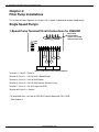
Single Speed Pumps . . . . . . . . . . . . . . . . . . . . . . . . . . . . . . . . . . . . . . . . . 22
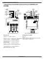
1-Speed Pump Terminal/Circuit Connections for PE653RC . . . . . . . . . . . . . . . . 22
1-Speed Pump Terminal/Circuit Connections for PE653RC with P5043ME . . . . . . . 24
2-Speed Pumps . . . . . . . . . . . . . . . . . . . . . . . . . . . . . . . . . . . . . . . . . . . . 26
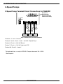
2-Speed Pump Terminal/Circuit Connections for PE653RC . . . . . . . . . . . . . . . . 26
2-Speed Pump Terminal/Circuit Connections for PE653RC with P5043ME . . . . . . . 28
Variable Speed Pumps . . . . . . . . . . . . . . . . . . . . . . . . . . . . . . . . . . . . . . . . 30
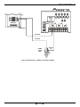
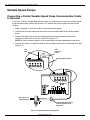
Connecting a Pentair Variable Speed Pump Communication Cable to Receiver . . . . 30
External Variable Speed Pump Hookup . . . . . . . . . . . . . . . . . . . . . . . . . . 31

www.intermatic.com
6
MultiWave Control System Installation Guide
Chapter 5:
Basic Wiring — 240V Cleaner/Lights/Actuators
. . . . . . . . . . . . . . . . . . . . 34
Cleaner . . . . . . . . . . . . . . . . . . . . . . . . . . . . . . . . . . . . . . . . . . . . . . . . . 34
Lights . . . . . . . . . . . . . . . . . . . . . . . . . . . . . . . . . . . . . . . . . . . . . . . . . . 35
Pool/Spa Actuators . . . . . . . . . . . . . . . . . . . . . . . . . . . . . . . . . . . . . . . . . 37
Chapter 6:
Heaters . . . . . . . . . . . . . . . . . . . . . . . . . . . . . . . . . . . . . . . . . . . . . . . . 38
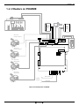
1 Heater on PE653 . . . . . . . . . . . . . . . . . . . . . . . . . . . . . . . . . . . . . . . . . . 38
1 or 2 Heaters on P5043ME . . . . . . . . . . . . . . . . . . . . . . . . . . . . . . . . . . . . . 39
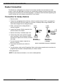
Heater Connection . . . . . . . . . . . . . . . . . . . . . . . . . . . . . . . . . . . . . . . . . . 40
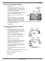
Connection for Jandy
®
Heaters . . . . . . . . . . . . . . . . . . . . . . . . . . . . . . . 40
Connection for Raypak
®
Heaters . . . . . . . . . . . . . . . . . . . . . . . . . . . . . . . 41
Connection for Hayward
®
Heaters . . . . . . . . . . . . . . . . . . . . . . . . . . . . . . 41
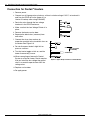
Connection for Pentair
®
Heaters . . . . . . . . . . . . . . . . . . . . . . . . . . . . . . . 42
Connection for Sta-Rite/Pentair
®
Heater with DDTC . . . . . . . . . . . . . . . . . . . . 43
Chapter 7:
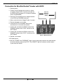
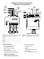
Blower/Chlorinator/Sensors . . . . . . . . . . . . . . . . . . . . . . . . . . . . . . . . . 44
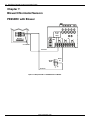
PE653RC with Blower . . . . . . . . . . . . . . . . . . . . . . . . . . . . . . . . . . . . . . . . 44
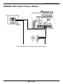
PE653RC with Cleaner Pump or Blower . . . . . . . . . . . . . . . . . . . . . . . . . . . . . 45
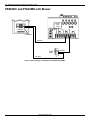
PE653RC and P5043ME with Blower . . . . . . . . . . . . . . . . . . . . . . . . . . . . . . . 46
Chlorinator . . . . . . . . . . . . . . . . . . . . . . . . . . . . . . . . . . . . . . . . . . . . . . 47
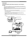
Connecting AutoPilot Salt Chlorine Generator Control Cable to Receiver . . . . . . . . 47
Sensors . . . . . . . . . . . . . . . . . . . . . . . . . . . . . . . . . . . . . . . . . . . . . . . . 48
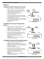
Installing the Water Temperature Sensor . . . . . . . . . . . . . . . . . . . . . . . . . . 48
Installing the Freeze (Air Temperature) Sensor . . . . . . . . . . . . . . . . . . . . . . . 48
Installing the Solar (Air Temperature) Sensor . . . . . . . . . . . . . . . . . . . . . . . . 48
NOTE: All trademarks are the property of their respective owners.

7Safety
Important Safety and Service Information
• IMPORTANT SAFETY INSTRUCTIONS, READ
AND FOLLOW ALL INSTRUCTIONS, SAVE THESE
INSTRUCTIONS
• Disconnect power at the circuit breaker(s) or disconnect switch(es) before installing or servicing.
• This control must be installed according to the National Electrical Code (NEC) and local code requirements. For
Canadian installations, section 10 & 68 of the CEC. IMPORTANT: This installation is subject to the approval by
the local inspection authority.
• The control panel to be a minimum of 3m (in Canada) or 5ft (in USA) from the inside wall of the pool, spa, or
pond, unless separated from the body of water by a fence, wall or other permanent barrier that will make the
unit inaccessible to persons in the water.
• Use up to #8 AWG wires, rated at least 90°C - COPPER Conductors ONLY.
• The control is not provided with integral GFCI protection for the lighting circuit. When this control is used to
power or switch an underwater luminaire, suitable GFCI protection shall be provided in the eld.
• This control should not be connected to any equipment which would cause bodily injury or property damage
should it be activated unexpectedly.
• For outdoor locations, raintight, or wet locations, conduit hubs that comply with requirements of the UL514B
(standard for tting for conduit and outlet boxes) are to be used.
• Bonding between conduit connections is not automatic and must be provided as part of the installation.
• If the power disconnect point is out of sight, lock it in the “OFF” position and tag it to prevent unexpected
application of power.
• This unit is not a safety disconnect. A proper sized fused disconnect or breaker of no more than 125A capacity
must be provided in the power supply circuit. Proper gauge wire should be based on local code requirements
of amperage and wire length.
• Do NOT exceed the maximum current carrying capacity of this control.
• Receiver must be mounted in a vertical (upright) position on top of the enclosure.
• KEEP DOOR CLOSED AT ALL TIMES when not servicing and secure with lock or tie-wrap.
WARNING
Risk of Fire or Electric Shock
NOTICE
• Do NOT touch circuit board components; contact can create a static discharge, which can damage the
microprocessor.

www.intermatic.com
8
MultiWave Control System Installation Guide
Informations importantes sur la sécurité et l’entretien
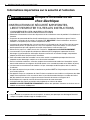
AVERTISSEMENT
Risque d’incendie ou de
choc électrique
AVIS
• INSTRUCTIONS DE SÉCURITÉ IMPORTANTES,
LIRE ET RESPECTER TOUTES LES INSTRUCTIONS,
CONSERVER CES INSTRUCTIONS
• Débrancher l’alimentation au niveau des disjoncteurs ou des sectionneurs avant de procéder à l’installation ou à
l’entretien.
• Ce panneau de commande doit être installé conformément aux codes de l’électricité en vigueur. Pour les
installations au Canada, voir les sections 10 et 68 du CCE. IMPORTANT : Cette installation est soumise au
contrôle et à l’acceptation par les autorités compétentes locales.
• Le panneau de commande doit être à un minimum de 3 m (au Canada) ou de 5 pi (aux États-Unis) de la paroi
intérieure de la piscine, du spa ou du bassin, sauf s’il est séparé de l’eau par une clôture, un mur ou autre
barrière permanente qui rend l’appareil inaccessible aux personnes se trouvant dans l’eau.
• Utiliser des ls jusqu’au n° 8 AWG, classés 90 °C minimum - Conducteurs en CUIVRE UNIQUEMENT.
• La commande n’est pas équipée d’un disjoncteur différentiel (GFCI) intégré pour la protection du circuit
d’éclairage. Si la commande est utilisée pour alimenter ou commuter un luminaire immergé, une protection
adaptée par GFCI devra être prévue dans l’installation.
• Cette commande ne doit être raccordée à aucun autre matériel susceptible de provoquer des blessures
corporelles ou des dommages matériels en cas d’activation inattendue.
• Pour les installations extérieures, utiliser des embouts de raccordement de conduit anti-intempéries ou pour
zone humide conformes aux exigences d’UL514B (norme sur les raccords de conduit et les boîtiers de prises).
• La liaison entre les raccordements de conduits n’est pas automatique et doit être prévue dans le cadre de
l’installation.
• Si le point de coupure n’est pas visible, le condamner en position ARRÊT et l’étiqueter pour éviter tout remise
sous tension imprévue.
• Cet appareil n’est pas un sectionneur de sûreté. Prévoir un sectionneur avec fusible ou un disjoncteur de calibre
adapté d’une capacité de 125 A au maximum dans le circuit d’alimentation électrique. Le calibre de l utilisé
doit être conforme aux normes en vigueur concernant l’intensité de courant et la longueur de l.
• Ne PAS dépasser la capacité maximale d’intensité de courant de cette commande.
• Le récepteur doit être montée en position verticale (debout) sur le dessus du boîtier.
• GARDER LA PORTE FERMÉE EN PERMANENCE en-dehors des opérations d’entretien et sécuriser avec un
cadenas ou une attache autobloquante.
• Ne pas toucher les composants du circuit imprimé ; le contact peut provoquer une décharge d’électricité
statique susceptible d’endommager le microprocesseur.

9
Chapter 1:
Overview
IMPORTANT: The installer must fill out the MultiWave Pool & Spa Control System
Worksheet for Programming at the back of this guide so that the controller can be
programmed.
The MultiWave Control System brings wireless control to a new level of simplicity. It features
push button control and a clear, easy-to-read backlit display panel. This manual provides
guidelines and instructions for installing the MultiWave Control System.
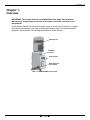
(PE653) Receiver
(2T2485GA)
Enclosure
Figure 1-1. PE653RC MultiWave Control System.
Water Temperature
Sensor (PA122)
PE953 Controller
Overview

www.intermatic.com
10
MultiWave Control System Installation Guide
MultiWave Components
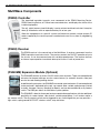
(PE953) Controller
The hand-held controller transmits user commands to the PE653 Receiving Device,
PE650 Receiving Device, or Z-Wave home control devices, and displays the status of the
installed equipment.
The unit, which features a backlit display, is water resistant and shock resistant. It requires
three (3) AA batteries with an expected battery life of one year.
When the components of a specic system are linked to a network, unique network ID
codes supplied by the receiver prevent unauthorized use of the system by neighboring
systems.
(PE653) Receiver
The PE653 receiver is the central hub of the MultiWave. It receives commands from the
PE953 controller to activate circuits. The receiver controls the ON/OFF operation of up to
ve circuits. It can also communicate with variable speed pumps. The receiver features
an internal supercapacitor to maintain data up to 8 hours in case of power loss.
(P5043ME) Expansion Module (Optional)
The P5043ME controls up to four 24 VAC water valve actuators. There are two dedicated
actuators for the pool and spa, one for a water feature (i.e. waterfall, fountain, slide) and
one for the solar heating/cooling feature.
In addition to the actuators, the P5043ME can control up to two heaters (1 heater dedicated
to the pool and 1 dedicated to the spa), can control other variable speed pumps (limited
to Jandy, Hayward, Century, Marathon or Speck), and can be controlled by a dry contact
switch. The USB port allows for MultiWave system updates.
The P5043ME is ideal for those pool and spa combination applications with the additional
possibility of a water feature, solar feature, variable speed pump, 1 or 2 heaters and/or a
dry contact switch. The dry contact switch can be triggered by any switching device you may provide —
light switch, spring wound AUTO/OFF, wireless switch, relay and more.

11 Overview
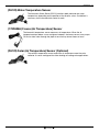
(PA122) Water Temperature Sensor
The Intermatic Water Sensor (PA122) monitors both pool and spa water
temperature, depending on the position of the diverter valves. Installation is
necessary for the thermostatic control to work.
(178PA28A) Freeze (Air Temperature) Sensor
The freeze/air temperature sensor measures air temperature. When the air
temperature drops below a user-congured setpoint, the freeze sensor turns pumps
ON to circulate water through the pipes to ensure they do not freeze or burst.
(PA122) Solar (Air Temperature) Sensor (Optional)
The solar/air temperature sensor measures air temperature near the solar
collector. It can be congured for either heating or cooling solar applications.

www.intermatic.com
12
MultiWave Control System Installation Guide
(PE24VA) 24-Volt Valve Actuator (Optional)
Designed with quality in mind, Intermatic’s 24-volt valve actuators provide
reliable control of 2-way and 3-way diverter valves for pool/spa combinations
and water features. The water ow can be altered for specic applications
through the adjustable cam, which rotates diverter valves to multiple degree
settings. The cam settings can be easily adjusted by simply removing the lid.
These valve actuators are compatible with all pool/spa valves currently offered in
the industry and will retrot into all pool/spa control systems.
• 24 VAC Input Voltage
• Automates compatible diverter valves for pool/
spa combos
• Adjustable cam rotates diverter valves to
multiple degree settings
• Designed to operate most 2-way and 3-way
diverter valves
• Shipping Weight - 3 lbs. (1.4 kg)
• Agency Approval - CSA/C-US
(PE30000) Load Center (Optional)
The PE30000 load center provides a safe and efcient environment for the control
components of MultiWave Pool/Spa Series Kits which include expansion module
and/or relay modules.
The PE30000 Series panel includes an eight-position 80 Amp breaker base, two
mechanism slots, and four décor knockouts for GFCIs and switches.
The panel provides a low voltage raceway for low voltage control lines (i.e. actuators,
sensors, etc…) and a convenient side knockout for an outdoor receptacle.
The panel is rated for indoor/outdoor use and is suitable for pool equipment control and for direct
connection to a wet-niche or no-niche luminaire.

13 Mounting
Chapter 2:
Mounting
Mounting the PE653RC System
Follow this procedure to mount the MultiWave enclosure and PE653 receiver.
1. Select a location to mount the receiver that is near the pool/spa equipment; at least 3m
(in Canada) or 5 ft (in USA) from the inside wall of the pool, spa, or pond, unless separated
from the body of water by a fence, wall, or other permanent barrier that will make the unit
inaccessible to persons in the water. NOTE: The receiver must be mounted in a vertical
(upright) position on top of the enclosure.
2. Select the knockouts to be used and insert a athead screwdriver into the slot and carefully
punch the 1/2" knockout loose and remove the slug.
NOTE: If a 3/4" knockout is required, remove the outer ring with pliers after removing the
1/2" knockout. Smooth the edge with a le if required.
NOTE: If a low voltage circuit or a heater control circuit is to be used, remove the low
voltage knockout from the PE653 enclosure.
3. Install conduit hub to knockout rated for outdoor locations, raintight, or wet locations that
complies with the requirements in UL 514B (standard for tting for conduit and outlet box).
4. Place the metal enclosure in the desired mounting location and mark the three mounting
holes. Install the top screw rst and then hang the enclosure by the keyhole. Then install the
bottom screws, tightening all screws for a secure mounting.
5. Install conduit as needed to comply with national and local electrical and safety codes.
6. Bond the enclosure in accordance with your state and local codes. Where required, connect a
No. 8 AWG solid copper wire to the enclosure with a Bonding Lug (part number 156T11047A).
Connect the bonding wire to an approved earth ground.
7. Identify and install all wires necessary to complete the installation. Allow a length of
approximately 18" (46 cm) of each wire at the metal enclosure for required connections of
junctions.
8. Connect wiring for circuits as required. Refer to the diagrams in Chapter 3 and Chapter 4 for
wiring suggestions for specic equipment combinations. All splices and wire nut connections
should be in the metal enclosure, not in the PE653 enclosure.
9. Check and tighten all connections and circuits.
10. Apply power.

www.intermatic.com
14
MultiWave Control System Installation Guide
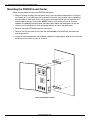
Mounting the PE30000 Load Center
Follow this procedure to mount the PE30000 load center.
1. Select a location to mount the load center that is near the pool/spa equipment; at least 3m
(in Canada) or 5 ft (in USA) from the inside wall of the pool, spa, or pond, unless separated
from the body of water by a fence, wall, or other permanent barrier that will make the unit
inaccessible to persons in the water. NOTE: Choose a at vertical surface or structure
capable of supporting the load center and allow space above the load center so that the
receiver can be mounted in a vertical (upright) position on top of the load center.
2. Remove the empty PE30000 enclosure from the kit.
3. Remove the #10 hex head screws from the outside back of the enclosure and attach the
mounting brackets.
4. Using the mounting brackets and hardware capable of supporting the load center, mount the
enclosure to the vertical surface or structure.
Figure 2-1. Mounting the load center.

15 Mounting
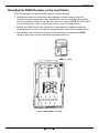
Mounting the PE653 Receiver on the Load Center
Follow this procedure to mount the PE653 Receiver on the load center.
1. Looking at the load center mounted on the supporting structure/surface, remove the
knockout located on the top right side. If no knockout is present, there should be a dimple
to use as a guide for drilling a 1-3/8" hole with a hole saw or punch. NOTE: DO NOT remove
the left-side knockout, as this is used to gain access to the low voltage raceway.
2. Remove the PE653 Receiver from the top of its small beige steel standard enclosure by
removing the plastic hub nut. Discard the standard enclosure and retain the plastic hub nut.
3. Use the plastic hub nut to mount the receiver to the top right of the load center. NOTE:
Gasket is required for rain tight connection for outdoor enclosures.
Figure 2-2. Mounting PE653 on load center.
Gasket

www.intermatic.com
16
MultiWave Control System Installation Guide
Ratings
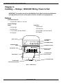
Chapter 3:
Installing — Ratings, 120V/240V Wiring, Power In/Out
Figure 3-1. PE653 Receiver.
Low Voltage Divider
(can be removed)
Load ON Indicator
(Green LEDs)
Circuit ON/OFF Switches
Include/Exclude Switch
AC Power & Status
Indicator (Red)
Low Voltage Knockout
Antenna Section
Threaded Conduit
Connection Bushing and Hub
120/240 VAC Selector
Switch
Fuse (250 VAC - 0.1 A)
Wiring Terminals
Controller Power In:
•
120/240 VAC, 50/60 Hz, 5 W max.
Contact Ratings:
Load 1
•
120/240 VAC
•
20 A Resistive
•
17 Full Load A, 80 Lock Rotor A
•
5A Tungsten
Loads 2-5
•
120/240 VAC
•
15 A Resistive
•
10 Full Load A, 60 Lock Rotor A
•
5A Tungsten
IMPORTANT: The installer must fill out the MultiWave Pool & Spa Control System Worksheet
for Programming at the back of this guide so that the controller can be programmed.

17 Installing — Ratings, 120V/240V Wiring, Power In/Out
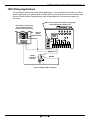
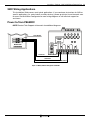
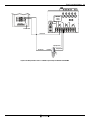
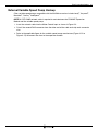
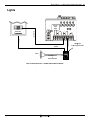
120V Wiring Applications
This Installation Guide covers most typical applications. If you need more instructions for 120V or
specic applications (i.e. water feature, auxiliary devices), please go to http://www.intermatic.com
to access the MultiWave Congurator for more wiring diagrams or call technical support for
assistance.
1 2
3
4
5
1234 56
78
9
Make sure that voltage selector switch is in 120V position
before applying power to terminals 1 & 2
Select breaker to match wire size
and load requirement. Observe
maximum control circuit capacity.
Single Pole
Breaker
120 VAC
1-Speed Pump
(Circuit 1)
HOT (Circuit 1)
NEUTRAL
RECEIVER
POWER
SUPPLY
NEUTRAL BUS
120V
240V
Figure 3-2. Wiring for 120V 1-Speed Pump

www.intermatic.com
18
MultiWave Control System Installation Guide
12 34 5
123456789
Make sure that voltage selector switch is in 120V position
before applying power to terminals 1 & 2
Select breaker to match wire size
and load requirement. Observe
maximum control circuit capacity.
1-Pole Breaker
1-Pole
Breakers
15 A. Max.
120 VAC
1-Speed Pump
(Circuit 1)
HOT (Circuit 1)
NEUTRAL
Aux.
(Circuit 2)
NOTE: The combined load on terminals 6 & 7
must NOT exceed 15 amps resistive
Aux.
(Circuit 3)
Aux.
(Circuit 4)
Aux.
(Circuit 5)
120 VAC
120 VAC
120 VAC
120 VAC
RECEIVER
POWER
SUPPLY
NEUTRAL BUS
120V
240V
Figure 3-3. Wiring for 120V 1-Speed Pump + Any 4 120V Auxiliary Components

19 Installing — Ratings, 120V/240V Wiring, Power In/Out
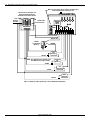
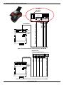
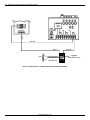
240V Wiring Applications
This Installation Guide covers most typical applications. If you need more instructions for 240V or
specic applications (i.e. water feature, auxiliary devices), please go to http://www.intermatic.com
to access the MultiWave Congurator for more wiring diagrams or call technical support for
assistance.
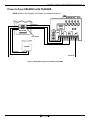
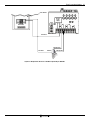
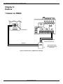
Power to/from PE653RC
NOTE: Contact Tech Support at Intermatic for additional diagrams.
Hot Line #1
2-Pole Breaker
Hot Line #2
Hot Line #1
RECEIVER
POWER
SUPPLY
NEUTRAL BUS
120V
240V
Figure 3-4. Wiring 240V incoming power to PE653RC.

www.intermatic.com
20
MultiWave Control System Installation Guide
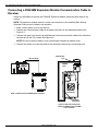
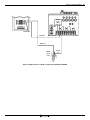
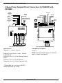
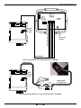
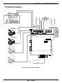
Connecting a P5043ME Expansion Module Communication Cable to
Receiver
Follow this procedure to connect the P5043ME Expansion Module communication cable to the
receiver.
NOTE: The expansion module connects to the same terminals as the AutoPilot Salt Chlorine
Generator. Both can be installed in the terminals.
1. Make sure the power is off at the receiver.
2. Connect the communication cable to the proper terminals on the expansion module. See
Figure 3-5.
3. Connect the green wire from the unattached end of the communication cable to the connector
terminal next to the Cat 5 cable. See Figure 3-5.
NOTE: Be sure to observe polarity when connecting the expansion module wires.
4. Connect the yellow wire from the cable to the connector terminal next to the green wire.
1 2 3 4 5 6 7 8 9
1 2 3 4 5
Observe Polarity
Power
Supply
120V
240V
Communication
Lines
PE30000
Series
Low Voltage
Compartment
High Voltage
Compartment
Figure 3-5. PE653 Receiver to P5043ME wiring connections.
Figure 3-6. High and low voltage wire
routing from PE653 Receiver to PE30000
Series Load Center.
La page est en cours de chargement...
La page est en cours de chargement...
La page est en cours de chargement...
La page est en cours de chargement...
La page est en cours de chargement...
La page est en cours de chargement...
La page est en cours de chargement...
La page est en cours de chargement...
La page est en cours de chargement...
La page est en cours de chargement...
La page est en cours de chargement...
La page est en cours de chargement...
La page est en cours de chargement...
La page est en cours de chargement...
La page est en cours de chargement...
La page est en cours de chargement...
La page est en cours de chargement...
La page est en cours de chargement...
La page est en cours de chargement...
La page est en cours de chargement...
La page est en cours de chargement...
La page est en cours de chargement...
La page est en cours de chargement...
La page est en cours de chargement...
La page est en cours de chargement...
La page est en cours de chargement...
La page est en cours de chargement...
La page est en cours de chargement...
La page est en cours de chargement...
La page est en cours de chargement...
-
 1
1
-
 2
2
-
 3
3
-
 4
4
-
 5
5
-
 6
6
-
 7
7
-
 8
8
-
 9
9
-
 10
10
-
 11
11
-
 12
12
-
 13
13
-
 14
14
-
 15
15
-
 16
16
-
 17
17
-
 18
18
-
 19
19
-
 20
20
-
 21
21
-
 22
22
-
 23
23
-
 24
24
-
 25
25
-
 26
26
-
 27
27
-
 28
28
-
 29
29
-
 30
30
-
 31
31
-
 32
32
-
 33
33
-
 34
34
-
 35
35
-
 36
36
-
 37
37
-
 38
38
-
 39
39
-
 40
40
-
 41
41
-
 42
42
-
 43
43
-
 44
44
-
 45
45
-
 46
46
-
 47
47
-
 48
48
-
 49
49
-
 50
50


dans d''autres langues
- English: Intermatic PE24VA Installation guide
Documents connexes
-
Intermatic MULTIWAVE PE653RC Programming And Usage Instructions
-
-
-
-
-
-
-
-
-
Intermatic IG2200 Manuel utilisateur
Autres documents
-
Miller H8HK Information produit
-
Astralpool CTX Series Mode d'emploi
-
Hayward RC9740WCCUB Le manuel du propriétaire
-
Jandy TruClear Installation & Operation Manual
-
Pentair Pool Color Sync Controller Guide d'installation
-
Pentair Color Sync Controller Color LED Pool Lights Guide d'installation
-
Jandy LXI Mode d'emploi
-
-
Jandy AquaLink RS Control Systems Manuel utilisateur
-
Bestway Chlorinator Le manuel du propriétaire