Bircher Reglomat ESM Translation Of The Original Instructions
- Taper
- Translation Of The Original Instructions

1
Vor Beginn der Installationsarbeiten muss diese Anleitung komplett gelesen werden.
Vor Installationsbeginn oder bei Vorbereitung der abzusichernden Fläche müssen
folgende Vorkehrungen getroffen werden:
• Die Anlage ist vor Beginn der Arbeiten spannungsfrei zu schalten.
• Die Anlage muss gegen Wiedereinschalten gesichert sein.
• Anschliessend muss die Spannungsfreiheit festgestellt werden.
• Die Phasen müssen geerdet und kurzgeschlossen werden.
• Benachbarte, unter Spannung stehende Teile müssen abgedeckt oder abgesperrt werden.
Sicherheitshinweise
• Voraussetzung für die Installation in industriellen
Anwendungen ist die Kenntnis der Normen
EN ISO 13849-1 und EN1760-1
• Die Montage, Inbetriebnahme, Änderung
und Nachrüstung darf nur von einer Fachkraft
ausgeführt werden.
• Die Sicherheitsvorschriften der Berufsgenossen-
schaft und für elektrische Installationen müssen be-
rücksichtigt werden.
• Nichtbeachtung der Sicherheitsvorschriften kann
zu Tod, schwerer Körperverletzung oder hohen
Sachschäden führen.
• Die Betriebsanleitung ist zu späterer
Wiederverwendung aufzubewahren.
Sicherheits-Systeme
Ein Sicherheits-System setzt sich immer aus
Schaltgerät, Matte und Abschlusswiderstand
zusammen. Bircher Reglomat Sicherheits-
Schalt
mattensysteme entsprechen dem PL e,
Kat. 3 nach EN ISO 13849-1.
Für Sicherheits-Systeme nach Maschinenrichtlinie
siehe auch Benutzerinformation unter:
www.bircher-reglomat.com
CE/FCC Zertifikat bezieht sich auf:
«ADVISORY for COMPLIANCE to COUNTRY
DIRECTIVE(S)»
Verpackung /Transport
Die Matten werden in speziell dafür hergestellten Ver-
packungen ausgeliefert.
Gewährleistung und Haftung
1. Die Gewährleistung und Haftung der Bircher Reglomat AG rich-
ten sich nach dem Kaufvertrag.
2. Die Gewährleistung und Haftung erlischt vorzeitig, wenn der
Kunde oder Dritte das Produkt nicht gemäss der vorliegenden
Betriebsanleitung einsetzen und/oder bedienen, der Kunde oder
Dritte unsachgemässe Änderungen oder Reparaturen vorneh-
men, der Kunde oder Dritte, falls ein Mangel aufge treten ist,
nicht umgehend alle geeigneten Massnahmen
zur Schadensminderung treffen und der Bircher Reglomat AG
Gelegenheit geben, den Mangel zu beheben.
3. Von der Gewährleistung und Haftung ausgeschlossen sind Schä-
den, die nicht nachweisbar infolge schlechten Materials, fehler-
hafter Konstruktion oder mangelhafter Ausführung entstanden
sind sowie Schäden, die aus anderen Gründen entstanden sind,
welche die Bircher Reglomat AG nicht zu ver treten hat.
4. Eine Haftung für Folgeschäden ist ausgeschlossen, soweit zwin-
gende produktehaftpflichtrechtliche Bestimmungen dem nicht
entgegenstehen.
5. Die Gewährleistungsansprüche aus dem Kaufvertrag gegen über
dem Händler werden durch diese Bestimmungen nicht berührt.
6. Bircher Reglomat AG entwickelt ihre Produkte zum Nutzen ihrer
Kunden stetig weiter. Bircher Reglomat AG behält sich das Recht
vor, ohne vorherige Ankündigung, an jedem in dieser Dokumen-
tation erwähnten Produkt, Änderungen vorzunehmen.
Bircher Reglomat AG, Wiesengasse 20, CH-8222 Beringen
Tel. +41(0)52 687 11 11, Fax +41(0)52 687 11 12
ESM-Matten
Originalbetriebsanleitung
Schaltmatten zur Aktivierung von
Maschinen und automatischen Türen.
DEUTSCH
209326Q
08/13

2
2
z
u empfehlen
– Lagertemperatur 0°C bis 40°C
– Matten in der angelieferten Verpackung zum
Montageort transportieren
– Ideale Lagerung: trocken, sauber und flach
– Nicht mehr als 10 Matten aufeinander stapeln
n
icht zu empfehlen
– Starkes Durchbiegen von Matten
– Matten vertikal lagern
– Stapeln verschieden grosser Matten
– Extreme Temperaturschwankungen
– Aussenlagerung
– Matten am Kabel ziehen
Vorbereitung zur Montage
1
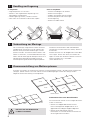
Handling und Lagerung
3
Zusammenstellung von Mattensystemen
Die zur Montage vorgesehene Fläche soll keine
Unebenheiten aufweisen und soll trocken sein.
Partikel sowie punktuelle Erhöhungen müssen
entfernt werden. Sind Kanten oder Löcher in der
Fläche zu erkennen, wird ein Bodenabstrich
emp-
fohlen. Vor der Montage der Rampenschiene
und
Ver legung der Verlängerungskabel wird eine
Funktionsprüfung der Mattenanlage empfohlen.
Detaillierte Informationen über die Bodenbe-
schaffenheit sind der Norm DIN 18202, Zeile 4 zu
entnehmen.
Matten kommen mit der Noppenseite nach oben
zum Liegen. Achten Sie darauf, dass beim Ver -
legen zwischen den einzelnen Matten immer ein
kleiner Luftspalt von 1 mm bleibt
(siehe Abschnitt 4.3)
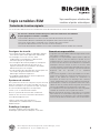
Es dürfen nur Matten zu Sicherheits-Systemen zusammengefügt werden, die über aktive Schaltkanten
verfügen. Matten dürfen nie an den Seiten mit den Kabelausgängen zueinander verlegt werden.
Folgende Zusammenstellung wird empfohlen:
ESM
ESM
ESM
ESM
ESM
ESM
Die Seite mit dem Kabelaustritt
ist NICHT schaltaktiv.
Schaltaktive Kante nach Norm EN1760-1
Die schaltaktiven Kanten sind an folgenden Merk-
malen zu erkennen:
– Matten mit Noppenoberflächenstruktur:
Die aussenliegenden Noppenreihen sind
gegenüber den übrigen Noppen abgesetzt.
– Matten ohne Oberflächenstruktur:
Die Matten sind auf der Mattenunterseite mit
einem Typenschild versehen.
aktive Kante
richtig
falsch

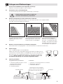
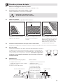
4
Verlegen von Mattenanlagen
V
ermassen und Markieren der Eckpunkte der Anlage
(Abstand zu Maschine, grobes Layout erstellen)
P
ositionieren der ersten Mattenbahn
(Ist die Ausrichtung, Vermassung bzw. Markierung in Ordnung?)
Matten mit Verbindungsstreifen miteinander verbinden
Die gezeigte Verbindungstechnologie ist von der Norm EN1760-1 nicht vorgeschrieben,
wird aber von Bircher Reglomat empfohlen.
Matten vor dem Anschliessen auf Funktion überprüfen
(Multimeter oder Durchgangsprüfer – Vorsicht bei Matten mit Abschlusswiderstand)
Kabel verlegen
(evtl. zu Kabelsträngen zusammenbinden)
Neben der elektrischen Signalübertragung findet über das Kabel auch ein
Luftaustausch zwischen Matte und Umgebung statt. Dies verhindert, dass
bei Änderungen der Umgebungstemperatur in der Matte ein Überdruck
entsteht. Wird das Kabel in eine elektrische Verteilbox geführt, darf
die Kabelverschraubung nur von Hand festgedreht werden.
Fixierung am Boden
Vorgebohrte Rampenschiene Z-Schiene
1. Sämtliche Rampenschienen um die 1. Schienen zu Maschinenseite hin anordnen
Mattenanlage anordnen 2. Bohrlöcher anzeichnen
2. Bohrlöcher anzeichnen 3. Fixierlöcher bohren
3. Fixierlöcher bohren
Kabelausgänge wenn immer möglich auf
der Seite der Z-Schienen positionieren.
Ankleben der einen Seite des
Verbindungsstreifens unter
der Matte.
Mittels Distanzierhilfe die nächste
Matte positionieren (Hilfsmittel:
Nylon-Hammer und Holzbrett)
Positionierte Matte belasten
damit sie nicht verschoben wer-
den kann, zu verbindende Seite
anheben, Schutzfolie vom Verbin-
dungsband abziehen, Matte vor-
sichtig ablegen und anpressen.
1mm
1 2 3
3
Rampenschiene
Kabel
Montageanschlag (ermöglicht
die Ausdehnung der Matte bei
Temperaturveränderungen)
KabelLuftspalt von ca. 0.5 mm
Z-Schiene
Matte
4
.1
4
.2
4.3
4.4
4.5
4.6

4
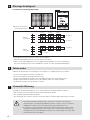
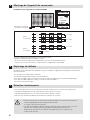
I
nstallation mit Schaltgeräten ESD3
• Schaltgerät auf DIN-Hutschine (35mm) aufschnappen.
• Mehrere Signalgeber können in Serie verdrahtet werden.
• Wird nur ein Signalgeber-Kanal am Schaltgerät ESD3 belegt, muss der andere Kanal
mit einem Widerstand 8.2 kOhm überbrückt werden (ist dem Schaltgerät beigelegt).
A
bschlusswiderstand
(intern oder extern)
Arbeitet die Matte oder das Schaltgerät nicht korrekt, sind folgende Punkte zu prüfen:
• Ist das System gemäss Schema verdrahtet?
• Stimmt die effektive Versorgungsspannung?
• Sind die Signalgeber so verlegt, dass die Kabel nicht geknickt oder verletzt sind?
• Liegen die Sicherheitsmatten flach auf dem Boden oder sind diese gewölbt?
• Ist Verschmutzung unter der Matte zu finden?
Vor Beginn der Wartungsarbeiten, muss dieser Abschnitt komplett gelesen werden!
• Die Sicherheitsfunktion jeder einzelnen Matte periodisch prüfen.
• Auf sichtbare Defekte periodisch prüfen.
• Zur Reinigung des Systems müssen sämtliche Anbau und Montagewinkel entfernt werden.
1
2
3
4
ESM 1 ESM 2 ESM 3
8.2 kOhm
8.2 kOhm
1
2
3
4
8.2 kOhm
8.2 kOhm
5
Montage Schaltgerät
6
Fehlersuche
7
Unterhalt /Wartung
• Sämtliche entfernten Abdeckungen, Schienen und Winkel, die während
den Wartungs- und Reini gungs arbeiten entfernt wurden, müssen wieder so
angebracht werden, dass die Sicherheitsfunktion gewährleistet ist.
• Es dürfen nur vom Hersteller zugelassene Teile ausgetauscht werden. Nicht
zugelassene Bauteile können dazu führen, dass die Sicherheitseinrichtung
nicht gemäss den Anforderungen funktioniert und die Anlage nicht mehr dem
Sicherheitszertifikat entspricht.
ESD 3
2 Systeme
ESD 3
1 System

5
Please read through these instructions fully before starting installation work.
Take the following safety precautions before starting installation or when preparing
the area to be protected:
• De-energise the system before starting work.
• The system must be safeguarded to prevent it from being switched on by a third party.
• Then it must be checked that power supply is not connected.
• The phases must be earthed and short-circuited.
• Adjacent live components must be covered or blocked off.
Safety Instructions
• Knowledge of standards
EN ISO 13849-1
and EN 1760-1
is a precondition for installation in industrial
applications
• Mounting, startup, modification and retrofitting of
the system may only be carried out by a specialist.
• The safety regulations issued by the Trade
Association and those for electrical installations
must be adhered to.
• Failure to comply with the safety regulations may
result in severe or fatal injury or serious damage
to property.
• Keep these instructions available
for further reference.
Safety Systems
A safety system is always composed of a switching
device, a mat and a terminating resistor. Bircher
Reglomat safety mat systems correspond to
PL e, cat.
3 acc. to EN ISO 13849-1.
For safety-systems acc. to machinery directive see
also user information under:
www.bircher-reglomat.com
CE/FCC Certification refers to:
«ADVISORY for COMPLIANCE to COUNTRY
DIRECTIVE(S)»
Packaging /Transport
The mats are delivered in specially constructed
packaging.
Bircher Reglomat AG, Wiesengasse 20, CH-8222 Beringen, Switzerland
Phone +41(0)52 687 11 11, Fax +41(0)52 687 11 12
Warranty and Liability
1. The warranty and liability of Bircher Reglomat AG are based
on the sales contract.
2.The warranty and liability shall expire prematurely,
should the client or third parties not use and/or operate the
product in compliance with existing operating instructions,
should incorrect changes or repairs be made by the client
or third parties, should the client or third parties, when a
fault has occurred, not take suitable steps at once for a re-
duction of possible damage/ losses and offer Bircher Reglo-
mat AG a chance for remedying the said fault.
3.The warranty and liability shall exclude any damage for
which there is no proof that it is due to poor materials,
faulty construction, poor workmanship, and any damage
caused by other reasons, for which Bircher Reglomat AG
cannot be held liable.
4.No liability can be assumed for any consequential damage,
provided this is not governed otherwise by applicable prod-
uct liability laws and regulations.
5.Warranty claims made against the seller on the basis of the
sales agreement are not affected by these regulations.
6.For the benefit of its customers Bircher Reglomat AG con-
stantly develops its products further. Bircher Reglomat AG
reserves the right to make changes to any of the products
described in this document without prior notice.
ESM mats
Translation of the original instructions
Switching mats for activation of
machinery and automatic doors
ENGLISH

6
2
R
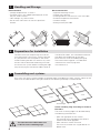
ecommended
– Storage temperature 0°C to 40°C
– Transport mats in the supplied packaging to where
they are to be installed
– Ideal storage: dry, clean and flat
– Do not stack more than 10 mats on top of one
another
N
ot recommended
– Significant bending of mats
– Storing mats vertically
– Stacking different sizes of mats in the same pile
– Extreme temperature fluctuations
– Outdoor storage
– Pulling mats by the cable
Preparations for installation
1
Handling and Storage
3
Assembling mat systems
The area where you are planning to install the
mat should have a flat and dry surface. Remove
any dirt particles and raised points. We
recom-
mend recoating the floor if it contains any cracks
or holes. We recommend conducting a function
test on the mat system before installing the edge
ramp
and lay ing the connection cables. Refer to
standard DIN 18202, line 4 for detailed informa-
tion about the composition of the floor.
Place the mats with the nubbing facing up.
Take care to leave a gap of 1 mm between
individual mats when laying them
(see section 4.3).
Only mats with active switching edges are allowed to be assembled into safety systems. Never lay the
sides with the cable outputs facing one another. The following assembly is recommended:
E
S
M
E
S
M
ESM
ESM
E
S
M
ESM
The side where the cable comes out
is NOT an active switching edge.
Active switching edge according to standard
EN 1760-1
The active switching edges can be detected by
the following characteristics:
– Mats with grip pads on the surface:
The outlying rows of grip pads are offset in
relation to the other grip pads.
– Mats without a surface structure:
The mats are marked with a type label on its
bottom side.
Active edge
Right
Wrong

7
4
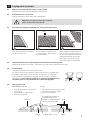
Laying mat systems
M
easure and mark out the corners of the system
(Distance from the machine, prepare a rough layout)
Position the first row of mats
(Are the alignment, dimensions and marking OK?)
J
oin the mats together optionally the using connection stripe
Check that the mats are functioning correctly before connecting them
(Multimeter or continuity tester – take care if the mats have a terminating resistor)
Lay the cables
(Combine into cable harnesses if necessary)
As well as their use for electrical signal transmission, the cables also
exchange air between the mat and the environment. This prevents
excessive pressure build-up in the mat due to changes in ambient
temperature. If the cable is routed to an electrical distribution box,
the cable gland is only allowed to be screwed finger-tight.
Fixing to the floor
Pre-drilled ramp rail Z-rail
1. Arrange all ramp rails around the 1. Arrange rails on the machine side
mat system 2. Mark the holes to be drilled
2. Mark the holes to be drilled 3. Drill the fixing holes
3. Drill the fixing holes
W
henever possible, position the outgoing
cables on the side of the Z-rails.
Stick one side of the connection
stripe under the mat.
Use a template to position the
next
mat (tools: nylon hammer
and wood board).
Apply weight to the positioned
mat so that it cannot move. Lift
up the side to be connected, pull
the backing foil off the connec-
tion stripe, carefully put down
the mat and press it into place.
1mm
1 2 3
ramp rail
Cables Cables
Gap of about 0.5mm
Z-rail
Mat
4
.1
4.2
4
.3
4.4
4.5
4.6
The expansion of the mat,
while the temperature
changes, is made possible
with the mounting stop.

8
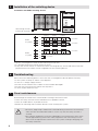
I
nstallation with ESD3 switching devices
• Clip the switching device onto the DIN mounting rail (35 mm).
• It is possible to connect several sensors in series.
• If only one sensor channel is used on the ESD3 switching device, the unused channel must be
jumpered with an 8.2kohm resistor (supplied with the switching device).
Terminating resistor
(
internal or external)
Please check the following points if the mat or the switching device do not operate correctly:
• Is the system wired up as shown in the diagram?
• Is the r.m.s. voltage supply correct?
• Are the sensors laid out so the cables are not kinked or damaged?
• Are the mats lying flat on the floor or are they bent?
• Is there any dirt under the mat?
Read through the whole of this section before starting maintenance work!
• Check the safety function of each individual mat at periodic intervals.
• Check for visible defects at periodic intervals.
• Remove all mounting and installation brackets when cleaning the system.
1
2
3
4
E
SM 1 ESM 2 ESM 3
8.2 kOhm
8.2 kOhm
1
2
3
4
8.2 kOhm
8.2 kOhm
5 Installation of the switching device
6
Troubleshooting
7 Care/ maintenance
• All covers, edge ramps and brackets removed during maintenance and cleaning
work must be reinstalled afterwards in such a way that the safety function is
assured.
• Only replace components with parts approved by the manufacturer. Parts which
are not approved may prevent the safety equipment from functioning in accor-
dance with the requirements and result in the system no longer complying with
the safety certificate.
ESD 3
2 systems
ESD 3
1 system

9
Ces instructions doivent être lues entièrement avant de commencer les travaux d’installation.
Les mesures suivantes doivent être prises avant de commencer l’installation
ou pour préparer la surface à surveiller:
• L’installation doit être mise hors tension avant de commencer les travaux.
• L’installation doit être verrouillée pour empêcher toute remise sous tension.
• S’assurer ensuite que l’installation n’est vraiment plus sous tension.
• Les phases doivent être mises à la terre et court-circuitées.
• S’assurer d’une bonne isolation vis-à-vis des installations voisines encore sous tension.
Consignes de sécurité
• Les normes EN ISO 13849-1 et EN1760-1 doivent
être connues pour toute application industrielle.
• Le montage, la mise en service, toute
modification et amélioration ne doivent être
exécutés que par un spécialiste.
• Les consignes de sécurité propres à l’entreprise
ainsi que celles édictées par les normes en
vigueur
concernant les installations électriques
doivent être prises en compte.
• Le non-respect des consignes de sécurité peut cau-
ser la mort, de graves blessures ou des
dommages matériels importants.
• Le mode d’emploi doit être conservé pour être
disponible ultérieurement.
Systèmes de sécurité
Un système de sécurité se compose toujours d’un ap-
pareil de commande, d’un tapis sensible et d’une ré-
sistance terminale. Les systèmes de tapis sen-sibles
de sécurité Bircher Reglomat correspondent
à la
PL e, cat. 3 selon EN ISO 13849-1.
Pour un système de sécurité selon la directive
machines voir aussi les informations d'utilisation:
www.bircher-reglomat.com
CE/FCC certification faire référence à:
«ADVISORY for COMPLIANCE to COUNTRY
DIRECTIVE(S)»
Emballage / transport
Les tapis sensibles sont livrés dans des
emballages spécialement fabriqués à cet effet.
Bircher Reglomat AG, Wiesengasse 20, CH-8222 Beringen, Suisse
Tél. +41(0)52 687 11 11, Fax +41(0)52 687 11 12
Garantie et responsabilité
1. La garantie et la responsabilité de Bircher Reglomat AG sont dé-
finies dans le contrat de vente.
2. La garantie et la responsabilité expirent avant le délai fixé
lorsque le client ou des tiers utilisent le produit et/ou le
manipulent sans se conformer aux instructions de service, que
le client ou des tiers effectuent des modifications ou réparations
inadéquates ainsi que lorsque le client ou des tiers, ayant
constaté un défaut, ne prennent pas immédiatement toutes les
mesures propres à limiter le dommage et per mettent à Bircher
Reglomat AG de procéder à la réparation
requise.
3. Sont exclus de la garantie et de la responsabilité tous les dom-
mages qui ne sont pas dus, conformément à des preuves y re-
latives, à des défauts de matériel, de construction ou
d’exécution, de même que les dommages dus à d’autres
causes, indépendantes de la volonté de Bircher Reglomat AG.
4. Sauf disposition contraire de la législation relative à la respon-
sabilité du fait du produit, Bircher Reglomat AG n’assume
aucune responsabilité pour les dommages consécutifs.
5. Ces stipulations ne portent pas atteinte aux droits à la garantie
résultant du contrat de vente à l’égard du revendeur.
6. Bircher Reglomat AG développe continuellement ses produits
dans l’intérêt de ses clients. Bircher Reglomat AG se réserve le
droit d’apporter des modifications, sans notification préalable,
à chacun des produits mentionnés dans cette documentation.
Tapis sensibles ESM
Traduction de la notice originale
Tapis sensible pour activation des
machines et portes automatiques
FRANCAIS

10
2
R
ecommandé
–
Température de stockage 0° C à 40°C
– Transporter les tapis sur le lieu de leur installation
dans l’emballage dans lequel ils ont été livrés
– Stockage idéal: à plat, dans un lieu propre et sec
– Ne pas empiler plus de 10 tapis les uns sur
les autres
N
on recommandé
–
Plier les tapis sensibles
– Le stockage des tapis à la verticale
– L’empilage de tapis de différentes tailles
– Les variations de température extrêmes
– Le stockage à l’extérieur
– Tirer les tapis par leur câble
Préparatifs de montage
1
Maniement et stockage
3
Assemblage de systèmes de tapis sensibles
La surface prévue pour le montage ne doit pas
présenter d’irrégularité et doit être sèche. Elimi-
ner les impuretés et les parties saillantes. Il est
recommandé de traiter le sol si des arêtes ou des
trous devaient être
détectés en surface. Contrôler
le
fonctionnement du système de tapis avant le
montage du rail anti-trébuchement et le câble de
raccordement. Des informations détaillées sur la
nature du sol se trouvent dans la norme DIN
18202, ligne 4.
Orienter le côté à nopes tes tapis vers le haut
.
Veiller
lors de la pose à ce qu’un jeu fonctionnel d’
1 mm
soit respecté entre les tapis (voir para-
graphe 4.3)
Pour l’assemblage des systèmes de sécurité il faut utiliser seulement des tapis sensibles avec des
bords actifs. Les côtés sur lesquels se trouvent les sorties de câble ne doivent jamais être posés en
face les uns des autres. L’assemblage suivant est recommandé:
ESM
ESM
ESM
ESM
ESM
ESM
Le(s) côté(s) de la sortie du
câble n’a(ont) pas de bord actif.
Bord actif selon la norme EN1760-1
Les arêtes actives se reconnaissent aux
caractéristiques suivantes:
– Tapis avec structure de surface pastillée:
Les rangées de pastilles extérieures sont plus
basses par rapport aux autres.
– Tapis avec structure lisse:
Les tapis sont marqué avec
une plaque sur le fond.
bords actifs
correct
incorrect

11
4
Pose de systèmes de tapis
M
esure et marquage des coins du système
(
distance par rapport à la machine, réaliser un marquage au sol)
Positionnement de la première rangée de tapis
Vérifier la disposition, la mesure et le marquage.
O
ption de montage
Relier les tapis entre eux par des bandes adhésives.
Contrôler le fonctionnement des tapis avant de les brancher.
(multimètre ou appareil de contrôle de continuité – attention aux tapis munis d’une résistance terminale)
Pose des câbles
(attacher éventuellement les câbles ensemble pour obtenir des faisceaux)
Le câble sert à la transmission électrique de signaux et à l’échange d’air
entre le tapis et l’environnement. Cela empêche qu’il y ait surpression en
cas de variations de la température ambiante. Si le câble est placé dans
un boitier de raccordement électrique, le presse-étoupe ne doit être
vissé qu’à la main.
Fixation au sol
Rail anti-trébuchement pré-percé Rail de fixation
1. Disposer tous les rails 1. Disposer les rails côté machine
autour du système de tapis sensible 2. Repérer les trous
2. Repérer les trous 3. Percer les trous de fixation
3. Percer les trous de fixation
Positionner si possible, les sorties
de câble du côté des rails de fixation.
Collage d’un côté de la bande
adhésive sous le tapis.
Positionner le tapis suivant en res-
pectant un jeu fonctionnel
d’ 1 mm.
Placer un poids sur le tapis afin
qu’il ne se déplace pas, soulever
légèrement le côté à coller, reti-
rer le film de protection de la
bande adhésive, poser le tapis
avec précaution et presser.
1mm
1 2 3
Rail anti-trébuchement
Câble CâbleJeu fonctionnel d’env. 0.5 mm
Rail de fixation
Tapis
4
.1
4.2
4
.3
4.4
4.5
4.6
La butée de montage
permet la dilatation du
tapis en cas de change-
ments de température.

12
Résistance terminale
(interne ou externe)
Les points suivants devront être contrôlés si le tapis sensible ou l’appareil de commande ne fonctionnent
pas correctement:
• Le système est-il câblé selon le schéma?
• La tension d’alimentation effective est-elle la bonne?
• Les tapis sensibles sont-ils installés de manière à ce que le câble ne soit pas plié ou endommagé?
• Les tapis sensibles reposent-ils à plat sur le sol ou sont-ils bombés?
• Le sol est-il sale sous le tapis?
Cette section doit avoir été lue entièrement avant de commencer les travaux de maintenance!
• Contrôler périodiquement le fonctionnement correct de tous les tapis.
• Contrôler périodiquement si les tapis présentent des défauts visibles.
• Tous les rails de montage doivent être ôtés pour nettoyer le système.
1
2
3
4
ESM 1 ESM 2 ESM 3
8.2 kOhm
8.2 kOhm
1
2
3
4
8.2 kOhm
8.2 kOhm
5
Montage de l’appareil de commande
6
Dépistage de défauts
7
Entretien / maintenance
• Tous les couvercles et rails qui ont été ôtés pendant les travaux de maintenance
et de nettoyage doivent être remontés de manière
à ce que la sécurité soit garantie.
• Les pièces échangées doivent avoir été autorisées par le constructeur. Les com-
posants non autorisés peuvent provoquer des disfonctionnements du
dispositif de sécurité et l’installation ne répondrait plus aux exigences du
certificat de sécurité.
ESD 3
2 systèmes
ESD 3
1 système
• Clipser l’appareil de commande sur le rail DIN (35 mm).
• Plusieurs tapis peuvent être câblés en série.
• Si un seul canal de l’appareil de commande est utilisé, le deuxième doit être
shunté avec une résistance de 8,2 kOhm (jointe à l’appareil de commande).
Installation avec l’appareil de commande ESD3
-
 1
1
-
 2
2
-
 3
3
-
 4
4
-
 5
5
-
 6
6
-
 7
7
-
 8
8
-
 9
9
-
 10
10
-
 11
11
-
 12
12


Bircher Reglomat ESM Translation Of The Original Instructions
- Taper
- Translation Of The Original Instructions
dans d''autres langues
- English: Bircher Reglomat ESM
- Deutsch: Bircher Reglomat ESM
Autres documents
-
BBC Bircher InTra6 Cat. 3 Manuel utilisateur
-
ASO Safety Solutions ELMON relay 41 DIN rail Le manuel du propriétaire
-
-
-
-
 Elmon rail 35-32 Le manuel du propriétaire
-
-
-
-
