Walter ICECUT 250 AUTO Le manuel du propriétaire
- Catégorie
- Outils électroportatifs
- Taper
- Le manuel du propriétaire

ICECUTTM 250 Auto
Magnetic Drilling Unit
39-D 252 (120V)
This Machine is CSA/UL certified.

2
Table of Contents
1) INTENDED USE .......................................................................................................................................... 3
2) GENERAL SAFETY RULES ........................................................................................................................... 3
3) INFORMATION PLATE SYMBOLS ............................................................................................................... 6
4) SPECIFICATIONS ........................................................................................................................................ 7
5) OPERATIONAL SAFETY PROCEDURES ........................................................................................................ 7
6) OPERATING INSTRUCTIONS ...................................................................................................................... 8
7A) CONTROL PANEL OPERATION ............................................................................................................... 10
7B) TAPPING FUNCTION.............................................................................................................................. 11
8) GEAR SELECTION ..................................................................................................................................... 12
9) MAGNET DETECTION .............................................................................................................................. 12
10) EXTENSION CABLE SELECTION .............................................................................................................. 13
11) MOUNTING OF CUTTERS ...................................................................................................................... 13
12) AUTOFEED FUNCTION........................................................................................................................... 13
13) SOLUTIONS FOR HOLE MAKING PROBLEMS ......................................................................................... 15
14) TROUBLESHOOTING .............................................................................................................................. 16
15) FITTING THE CHUCK .............................................................................................................................. 18
16) MAINTENANCE ...................................................................................................................................... 18
17) WARRANTY STATEMENT ....................................................................................................................... 20
FRANÇAIS .................................................................................................................................................... 23
ESPAÑOL ..................................................................................................................................................... 42
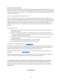
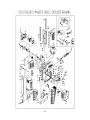
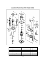
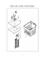
PARTS LIST ................................................................................................................................................... 62

3
1) INTENDED USE
The intended use of this magnetic drill is to drill holes in ferrous metals. The magnet is used to hold the
drill in place whilst the drill is functioning. It is designed for use in fabrication, construction, railways,
petrochemical and any other applications when drilling ferrous metal. Any deviation from its intended
use will not be covered by warranty.
2) GENERAL SAFETY RULES
WARNING! When using electric tools basic safety precautions should always be followed to reduce
the risk of fire, electric shock and personal injury. Failure to follow all instructions listed below, may
result in electric shock, fire and/or serious personal injury.
SAVE THESE INSTRUCTIONS
WORK AREA
1. Keep your work area clean and well lit. Cluttered benches and dark areas invite accidents.
2. Do not operate power tools in explosive atmospheres, such as in the presence of flammable
liquids, gases, or dust. Power tools create sparks which may ignite the dust or fumes.
3. Keep bystanders, children, and visitors away while operating a power tool. Distractions can
cause you to lose control.
ELECTRICAL SAFETY
1. Grounded tools must be plugged into an outlet properly installed and grounded in accordance
with all codes and ordinances. Never remove the grounding prong or modify the plug in any
way. Do not use any adaptor plugs. Check with a qualified electrician if you are in doubt as to
whether the outlet is properly grounded. If the tools should electrically malfunction or break
down, grounding provides a low resistance path to carry electricity away from the user.
2. Avoid body contact with grounded surfaces such as pipes, radiators, ranges and refrigerators.
There is an increased risk of electric shock if your body is grounded.
3. Don't expose power tools to rain or wet conditions. Water entering a power tool will increase
the risk of electric shock.
4. Do not abuse the cord. Never use the cord to carry the tools or pull the plug from an outlet.
Keep cord away from heat, oil, sharp edges or moving parts. Replace damaged cords
immediately. Damaged cords increase the risk of electric shock.
5. When operating a power tool outside, use an outdoor extension cord marked "W-A" or "W".
These cords are rated for outdoor use and reduce the risk of electric shock.

4
PERSONAL SAFETY
1. Stay alert, watch what you are doing and use common sense when operating a power tool. Do
not use tools when tired or under the influence of drugs, alcohol, or medication. A moment of
inattention while operating power tools may result in serious personal injury.
2. Dress properly. Do not wear loose clothing or jewelry. Contain long hair. Keep your hair,
clothing, and gloves away from moving parts. Loose clothes, jewelry or long hair can be caught in
moving parts.
3. Avoid accidental starting. Be sure switch is off before plugging in. Carrying tools with your finger
on the switch or plugging in tools that have the switch on invites accidents.
4. Remove adjusting keys or wrenches before turning the tool on. A wrench or a key that is left
attached to a rotating part of the tool may result in personal injury.
5. Do not overreach. Keep proper footing and balance at all times. Proper footing and balance
enables better control of the tool in unexpected situations.
6. Use safety equipment. Always wear eye protection. Dust mask, non-skid safety shoes, hard hat
or hearing protection must be used for appropriate conditions.
TOOL USE AND CARE
1. Use clamps or other practical way to secure and support the workpiece to a stable platform.
Holding the work by hand or against your body is unstable and may lead to loss of control.
2. Do not force tool. Use the correct tool for your application. The correct tool will do the job better
and safer at the rate in which it is designed.
3. Do not use tool if switch does not turn it on or off. Any tool that cannot be controlled with the
switch is dangerous and must be repaired.
4. Disconnect the plug from the power source before making any adjustments, changing
accessories, or storing the tool. Such preventive safety measures reduce the risk of starting the
tool accidentally.
5. Store idle tools out of reach of children and other untrained persons. Tools are dangerous in the
hands of untrained users.
6. Maintain tools with care. Keep cutting tools sharp and clean. Properly maintained tools, with
sharp cutting edges are less likely to bind and are easier to control.
7. Check for misalignment or binding of moving parts, breakage of parts, and any other condition
that may affect the tools operation.If damaged, have the tool serviced before using. Many
accidents are caused by poorly maintained tools.
8. Use only accessories that are recommended by the manufacturer for your model. Accessories
that may be suitable for one tool, may become hazardous when used on another tool.
9. Always use safety chain. Mounting can release.
SERVICE
1. Tools service must be performed only by qualified repair personnel. Service or maintenance
performed by unqualified personnel could result in a risk of injury.
2. When servicing a tool, use only identical replacement parts. Follow instructions in the
Maintenance section of this manual. Use of unauthorized parts or failure to follow Maintenance
Instructions may create a risk of electric shock or injury.

5
ADDITIONAL IMPORTANT SAFETY NOTES
1. Remove the power supply before carrying out any adjustment, servicing or maintenance.
2. Consider work area environment.
• Do not expose tools to rain.
• Do not use tools in damp or wet locations.
• Keep work area well lit (500 Lux recommended).
• Do not use tools in the presence of flammable liquids or gases.
• Ensure there is adequate space to gain access to the plug, mains and motor on/off switches.
3. Guard against electric shock:
• Avoid body contact with earthed or ground surfaces (e.g. pipes, radiators, cookers and
refrigerators). Electric safety can be further improved by using a high-sensitivity (30 m
A/0.1s) residual current device (RCD).
4. Keep other persons away. Do not let untrained persons, especially children, touch the tool or the
extension cord and keep them away from the work area.
5. Store idle tools when not in use. All tools should be stored in a dry locked-up place, out of reach of
children.
6. When using the drill, always ensure a safe operating distance from any swarf and do not reach into
the cutting area, or near the cutter, when the machine is running.
7. Connect dust extraction and collecting equipment, if devices are provided, ensuring these are
properly connected and used.
8. Do not overreach! Keep proper footing and balance at all times.
9. Maintain tools with care;
• Keep cutting tools sharp and clean for better and safer performance.
• Regularly check the machine for any wear or damage.
• Ensure the machine is clean and free from debris prior to use.
• Remove from the mains prior to any maintenance.
• Follow instructions for lubricating and changing accessories.
• Inspect tool cords periodically and if damaged have it repaired by an authorized Walter service
facility.
• Inspect extension cords periodically and replace if damaged.
• Keep handles dry, clean and free from oil and grease.
10. Disconnect tools from the power supply when not in use, before servicing or when changing
accessories such as cutters.
11. Form the habit of checking to see that keys and adjusting wrenches are removed from the tool
before turning it on.
12. Use extension leads only intended for outdoor use when the tool is used outdoors.
13. The vibration emissions during actual use can differ from the declared total value depending on the
ways in which the tool is being used.
14. Watch what you are doing, use common sense and do not operate the tool when you are tired. Do
not operate the machine when under the influence of alcohol or any illegal substances.
15. Check damaged parts

6
• Before further use of tool, it should be carefully checked to determine that it will operate
property and perform its intended function.
• Check for alignment of moving parts, binding of moving parts, breakage of parts, mounting and
any other conditions that may affect its operation.
• A guard or other part that is damaged should be properly repaired or replaced by an authorized
service centre unless otherwise indicated in this instruction manual.
• Have defective switches replaced by authorized service centre,
• Do not use the tool if the switch does no turn it on and off.
16. The use of any accessory or attachment, other than ones recommended in this instruction manual,
may present a risk of personal injury.
17. Have your machine repaired by a qualified Walter technician. This electric tool complies with the
relevant safety rules. Qualified persons using original spare parts should only carry out repairs
otherwise this may result in considerable danger to the user.
18. Never operate the machine if parts are missing or damaged.
19. Never direct jets of water or flammable liquids over the drill.
20. Operator must be physically able to handle the weight of the machine.
21. Operator should be trained in the use of the machine.
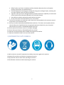
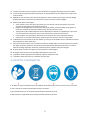
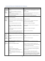
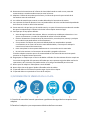
3) INFORMATION PLATE SYMBOLS
1
1 2 3 4
1 2 3 4
1. Refer to the user manual for operational and safety issues with regard to this machine.
2. Dispose of the machine and electrical components correctly.
3. Eye protection must be worn when operating the machine.
4. Ear defenders must be worn when operating the machine.

7
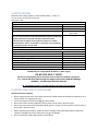
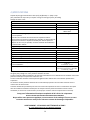
4) SPECIFICATIONS
Maximum hole cutting capacity in mild steel (Ø X DoC) = 2-3/8” x 3”
(3” DoC requires 2-piece pilot pin 05-Z 032)
Arbor bore = MT2
Motor Unit
Voltage
120V 50-60Hz
Normal full load
14A
Electro Magnet
0.53A
Size
200mm long
98mm wide
Holding Force at 20°C with 25mm minimum plate thickness
The use on any material less than 25mm thick will progressively reduce the
magnetic performance. If possible, substitute material should be
positioned under the magnet and work piece to equate to a suitable
material thickness. If this is not possible, an alternative secure method of
restraining the machine must be used.
1378kgs
Total Load (magnet + motor)
14.53 amps
Overall Dimensions
Height - maximum extended
586mm
Height - minimum
450mm
Width (including capstan fitting)
255mm
Length Overall (including guard)
395mm
Net Weight
18.5Kg
Product Code
Icecut 250 Auto (39-D 252)
Suitable only for a single phase 50-60Hz A.C. power supply
DO NOT USE ON D.C. SUPPLY
Do not use your magnetic drill on the same structure when arc welding is in progress.
D.C. current will earth back through the magnet and cause irreparable damage.
WARNING: THIS APPLIANCE MUST BE EARTHED!
NB: ANY MODIFICATIONS TO THIS MACHINE WILL INVALIDATE THE GUARANTEE
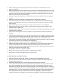
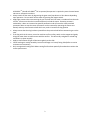
5) OPERATIONAL SAFETY PROCEDURES
READ BEFORE USING THE MACHINE
• When using electrical tools, basic safety precautions should always be followed to reduce the risk of
electric shock, fire and personal injury.
• Ensure the magnet is off before plugging in the machine.
• Do not use in wet or damp conditions. Failure to do so may result in personal injury.
• Do not use in the presence of flammable liquids, gases or in high risk environments. Failure to do so
may result in personal injury.
• Before activating the machine, inspect all electrical supply cables (including extension leads) and
replace if damaged. Do not use if there are any signs of damage.
• Only use extension cables approved for site conditions.

8
• Before activating the machine, always check the correct function of all operational systems,
switches, magnet etc.
• Before operating, the machine must be securely restrained to a fixed independent feature by using
safety strap and stationary rings. Affix the stationary rings into the magnet, uppermost side hole to
reduce the potential free movement. Should the magnet become detached from the work piece.
Failure to do so may result in personal injury.
• Always wear approved eye protectors, ear defenders and recommended PPE when operating the
machine.
• Disconnect from power source when changing cutters or working on the machine.
• Cutters and swarf are sharp, always ensure that hands are adequately protected when changing
cutters or removing swarf. Use a tool or brush where necessary to remove any swarf or the cutter
from the arbor.
• Before operating the machine, always ensure cutter-retaining screws are secured tightly.
• Regularly clear the work area and machine of swarf and dirt, paying particular attention to the
underside of the magnet base.
• Always remove tie, rings, watches and any loose adornments that might entangle with the rotating
machinery before operating.
• Always ensure that long hair is securely enclosed by an approved restraint before operating the
machine.
• Should the cutter become stuck in the work piece, stop the motor immediately to prevent personal
injury. Disconnect from power source and turn arbor to and fro. Do not attempt to free the cutter
by switching the motor on and off. Wear safety gloves to remove the cutter from the arbor.
• If the machine is accidentally dropped, always thoroughly examine the machine for signs of damage
and check that it functions correctly before resuming drilling.
• Regularly inspect the machine and check for any damaged or loose parts.
• Always ensure when using the machine in an inverted position that only the minimum amount of
coolant is used and that care is taken to ensure that coolant does not enter the motor unit.
• Cutting tools may shatter, always position the guard over the cutter before activating the machine.
Failure to do so may result in personal injury.
• On completion of the cut, a slug will be ejected.
• When not in use always store the machine in a safe and secure location.
• Always ensure that approved WALTER agents conduct repairs.
6) OPERATING INSTRUCTIONS
• Keep the inside of the cutter clear of swarf. It restricts the operating depth of the cutter.
• Ensure that the coolant bottle contains sufficient cutting oil to complete the required operating
duration. Refill as required.
• Occasionally depress the pilot to ensure cutting fluid is being correctly metered.
• To start the machine, follow the control panel operation instructions. The Icecut machine is fitted
with a dual motor protection system to fully ensure safety and extended life of the motor. The
ACCUDRILLTM protection (found on the control panel) gives a clear and visible indication to the user
of torque being applied to the motor, once the prescribed level is reached the motor is protected by
automatic cut out. To re-start your machine, the operator will simply press the start button again
(blue tapping button should a protection mode occur during tapping). If, however the speed
controller protection is activated, this is torque sensor regulated at a pre-determined value above

9
ACCUDRILLTM (should ACCUDRILLTM fail to operate) the operator is required to press the start button
twice to re-activate the machine.
• Always switch off the motor by depressing the green start/stop button or blue button depending
upon operation. Do not switch off the motor by pressing the magnet switch.
• Apply light pressure when commencing the cut of a hole until the cutter is introduced into the work
surface. Pressure can then be increased sufficiently to load the motor. Excessive pressure is
undesirable, it does not increase the speed of penetration and will cause the safety overload
protection device to stop the motor (the motor can be restarted by operating the motor start
button) and may cause excessive heat which may result in inconsistent slug ejection
• Always ensure that the slug has been ejected from the previous hole before commencing to cut the
next.
• If the slug sticks in the cutter, move the machine to a flat surface, switch on the magnet and gently
bring the cutter down to make contact with the surface. This will usually straighten a cocked slug
and allow it to eject normally.
• Apply a small amount of light oil lubricant regularly to the slide.
• Cutter breakage is usually caused by insecure anchorage or a loosely fitting slide (Refer to routine
maintenance instructions).
• Only use approved cutting fluid. Walter cutting fluid has been specially formulated to maximise the
cutters performance.

10
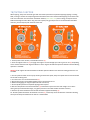
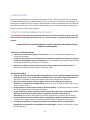
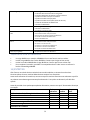
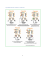
7A) CONTROL PANEL OPERATION
ACCUDRILL™ Technology
Green Zone
Perfect, try to keep in
the green zone for
the best cut and
optimum machine
performance.
Yellow Zone
A little too much
pressure on the drill,
ease off to get
backto the green
zone.
Red Zone
Overload: Back off
immediately as too
much force will cause
the motor to cut off if
you continue.
ACCUDRILL™ Technology
Designed for you to get the most out of your
machine and your cutters. ACCUDRILL has an
easy-to-read panel that indicates when you are
drilling with too much force, which will damage
the machine and the cutters. Allow the cutter to
do the work and you will find that a much
smoother hole and faster drilling time is
achieved.

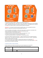
11
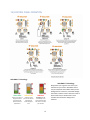
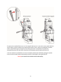
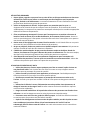
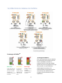
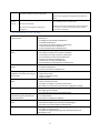
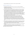
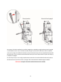
7B) TAPPING FUNCTION
When tapping, always use the lowest gear with the lowest speed. Never tap without applying tapping or cutting
fluid, ensuring a smooth cut and prolonged tool life.Drill the hole to the recommended tapping size for the thread
to be cut. Information can be found on the Walter website (www.walter.com).Once cutting, the tap will start to
feed itself through the hole. When using the reverse speed, only gentle pressure on the feed handles should be
necessary, and the tap will push itself out of the hole.
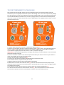
1. Ensure power to the machine, red LED will illuminate (1).
2. Press the magnet switch on (2) to engage the magnet. The LED will light up in either green or red (3). Depending
on the material thickness and magnetic adhesion. Green magnet LED indicates optimum adhesion achieved.Drilling
operation is available.
Warning if red magnet LED is illuminated this indicates optimum adhesion not achieved. Drilling operation is still
available.
3. Use the speed controller on the top cap housing to dictate the speed, always use speeds that are recommended
for the drill size being used.
4. Turn the motor on in the forward direction (4).
5. Drill the hole to the recommended tapping size for the thread to be cut.
6. Without disengaging the magnet replace the drill with the tap.
7. Set the spindle speed to the required tapping speed required.
8. Start the drill spindle in the forward direction (4) and feed the tap into the hole until it begins to cut. Once
cutting the tap will feed itself through, only gentle pressure on the feed handles should be necessary.
9. Once the tap has threaded the hole the drill should be stopped immediately (4).
10. The drill spindle should then be switched to reverse (5), and the tap can be fed back out of the hole. Allowing
the tap to be safely extracted from the hole at a reduced RPM.

12
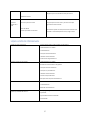
8) GEAR SELECTION
The Icecut 250Auto magnetic drill is fitted with a 2-speed gearbox.
The gear is used to reduce the output speed when using larger cutters.
Slide Selector Position
Speed Controller Setting
Level 1
Level 2
Level 3
Level 4
Level 5
Level 6
High Speed /\
200/min
260/min
320/min
380/min
440/min
500/min
Low Speed \/
100/min
133/min
166/min
199/min
232/min
265/min
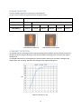
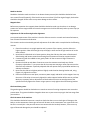
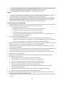
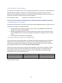
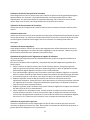
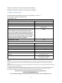
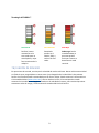
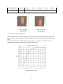
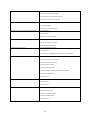
9) MAGNET DETECTION
It is advised that when working on thin material a packing piece should be used to increase the material
thickness under the magnet. Working on thin material without a packing piece will reduce the magnet
holding force.
It is advised that the drill is to be operated on ferrous material 12mm thick and above. Damage to the
magnet base, such as pitting, will affect the strength of the magnet holding force.
Slide Selector Position Up
Slide Selector Positon Down
Material Thickness in mm
Kg

13
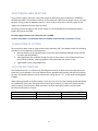
10) EXTENSION CABLE SELECTION
The machine is factory fitted with a 9-3/4 foot length of cable having three conductors 14 AWGLIVE,
NEUTRAL and EARTH. If it becomes necessary to fit an extension cable from the power source, care must
be taken in using a cable of adequate capacity. Failure to do so will result in a loss of traction by the
magnet and a reduction of power from the motor.
Assuming a normal AC supply of the correct voltage, it is recommended that the following extension
lengths shall not be exceeded:
For 120V supply:3.5 metres (11.5 feet) of 3 core x 14 AWG
ALWAYS DISCONNECT THE MACHINE FROM THE POWER SOURCE BEFORE CHANGING CUTTERS.
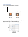
11) MOUNTING OF CUTTERS
The machine has been made to accept cutters having 19.05mm (3/4”) dia. Weldon shanks.The following
procedure is to be used when mounting cutters:
• With the machine in the upright position, ensure the Arbor Assembly (48H590) is fully inserted
into Arbor Spindle (48H596).
• Take appropriate pilot and place through the hole in cutter shank. Insert shank of cutter into
bore of Arbor Assembly, ensuring alignment of two drive flats with socket screws.
• Tighten both screws using hexagon key.
12) AUTOFEED FUNCTION
The autofeed function is an efficient way of drilling that allows for multiple units to be operated at the
same time, by one operator. The Icecut 250Auto can be operated both manually and with the autofeed
function. The autofeed function can be used for core cutting up to 2”x 2”*, as well as twist drilling (1/2”-
1” only).
When operating the drill in autofeed mode, it must be set at one of the two following speeds depending
on the diameter of the cutter being used.Prior to starting the machine, the electronic speed controller
requires setting, if the electronic speed controller is set after starting the machine, the automatic
function will not perform correctly.
Cutter Diameter
Gear box setting
Dialspeed setting
<1”
High
6
>1”
Low
6
*The Autofeed function has been optimized to work in low-to-medium carbon steels.

14
To operate the autofeed function turn on the mag drill and ensure it is set to the correct speed. With the
unit turned on, push the capstan lever towards the machine. Once in place, the autofeed is activated
and the spindle will begin to plunge.Once the drilling operation is completed, the spindle will
automatically retract until the cutter is free from the workpiece and the machine will turn off.
In the case where the spindle does not retract completely, deactivate autofeed by pulling the capstan
levers into the manual position and manually retract the cutter before turning the drill off.
Warning do not operate the autofeed function while tapping.

15
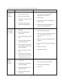
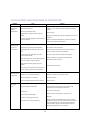
13) SOLUTIONS FOR HOLE MAKING PROBLEMS
Problem
Cause
Remedy
1) Magnetic
base won’t
hold
effectively
1. Material being cut may be too
thin for efficient holding.
2. Swarf or dirt under magnet.
3. Irregularity on magnet contact or
workpiece.
4. Insufficient current going to
magnet during drilling cycles.
1. Attach an additional piece of metal under
the magnet, or mechanically clamp
magnetic base to work-piece.
2. Clean magnet.
3. Use extreme care; file any imperfections
flush to surface.
4. Confirm power supply and output from
control unit, check supply cable.
2) Cutter skips
out of centre-
punch mark
at initiation of
cut
1. Magnetic base is not holding
effectively.
2. Worn arbor bushing and/or
ejector collar.
3. Too much feed pressure at start
of cut.
4. Cutter is dull, worn, chipped or
incorrectly sharpened.
5. Poor centre-punch mark; weak
pilot spring; pilot not centred in
centre-punch mark.
6. Worn or bent pilot, worn pilot
hole.
7. Loose bolts on motor bushing
support bracket, main casting or
loose gib adjusting set screws.
1. See causes and remedies above.
2. New arbor bushing is needed.
3. Light pressure only is needed until a groove
is cut. The groove then serves as a
stabilizer.
4. Replace or re-sharpen. Sharpening service is
available.
5. Improve centre-punch and/or replace worn
parts
6. Replace part or parts
7. Adjust where necessary
3) Excessive
drilling
pressure
required
1. Incorrectly re-sharpened, worn or
chipped cutter.
2. Coming down on swarf lying on
surface of workpiece.
3. Gib strips out of adjustment or
lack of lubrication.
4. Swarf accumulated (packed)
inside cutter.
1. Re-sharpen or replace.
2. Take care not to start a cut on swarf.
3. Adjust setscrews and lubricate.
4. Clear cutter.

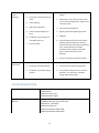
16
4) Excessive
cutter
breakage
1. Steel swarf or dirt under cutter.
2. Incorrectly re-sharpened or worn
cutter.
3. Cutter skipping.
4. Slide needs adjustment.
5. Cutter not attached tightly to
arbor.
6. Insufficient use of cutting oil or
unsuitable type of oil.
7. Incorrect speed
1. Remove cutter, clean part thoroughly and
replace.
2. Always have a new cutter on hand to refer
to for correct tooth geometry, together with
instruction sheet.
3. See causes and remedies (2).
4. Tighten grub screws supporting the slide.
5. Retighten.
6. Inject oil of light viscosity into the coolant-
inducing ring and check that oil is being
metered into cutter when pilot is depressed.
If not, check pilot groove and arbor
internally for dirt or apply oil externally.
(Even a small amount of oil is very
effective).
7. Ensure correct gear is used for the cutter.
5) Excessive
cutter wear
1. See cause and remedy above
2. Incorrectly re-sharpened cutter.
3. Insufficient or spasmodic cutting
pressure.
1. Refer to instructions
2. A new cutter for proper tooth geometry.
3. Use sufficient steady pressure to slow the
drill down. This will result in optimum
cutting speed and chip load.
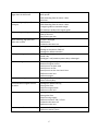
14) TROUBLESHOOTING
Magnet and motor do not function
-Damaged or defective wiring
- Defective fuse
- Defective control unit
- Defective power supply
Magnet does function, the motor
does not
- Damaged or defective wiring
- Carbon brushes are stuck or worn out
- Defective on / off switch
- Defective control unit
- Defective armature and/or field
- Defective protective reed switch

17
Hole cutters break quickly, holes are
bigger than the hole cutter
- Play in the guide
- Bent spindle
- Shaft extending from the motor is bent
- Pilot bent
Motor running roughly and/or
seizing up
- Bent spindle
- Shaft extending from the motor is bent
- Triangular guide not mounted straight
- Dirt between spindle and triangular guide
Motor making a rattling sound
- Gear ring (bottom of the armature) worn out
- Gear(s) worn out
- No grease in gear box
Motor humming, big sparks and
motor has no force
- Armature damaged
- Field burned
- Carbon brushes worn out
Motor does not start or fails.
- Damaged or defective wiring
- Damage to armature or field coil
- Damaged or defective brushes
Guiding takes a great deal of effort
- Guide is set too tight
- Guide is dry
- Guide/gear- rack/rotation system is dirty or damaged
Insufficient magnetic force
- Bottom of magnet not clean and dry
- Bottom of magnet not flat
- Work piece is not bare metal
- Work piece is not flat
- Work piece is too thin less than 3.5mm
- Defective control unit
- Defective magnet
Frame under voltage
- Damaged / defective wiring
- Motor seriously dirty
Fuse blows when magnet switch is
turned on
- Damaged or defective wiring
- Wrong value fuse
- Defective magnet switch
- Defective control unit
Fuse blows when motor is started up
- Damaged or defective wiring
- Wrong value fuse
- Motor running roughly
- Defective armature and / or field
- Carbon brushes worn out
- Defective control unit
Rotation system free stroke too long
- Loose or defective gear-rack
- Defective rotation system

18
15) FITTING THE CHUCK
1. The machine comes supplied with an Arbor Shank (48H591) & 13mm Chuck (39D008).
2. Insert 48H591 into Arbor Spindle (48H596), ensure a good and tight fit is achieved.
3. Insert 39D008 into 48H591, ensure a good and tight fit is achieved.
4. Replacing the chuck is the reverse sequence, by utilising 48H460 (Drift).
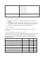
16) MAINTENANCE
In order to get the best life out of your Walter machine, always keep it in good working order.
A number of items must always be checked on Walter machines.
Before starting any job, always make sure the machine is in good working order and that there are no
damaged or loose parts. Any loose parts must be tightened.
Before proceeding with any maintenance work be certain that the power supply is disconnected.
Description
Every operation
1 week
1 Month
Visual check of
machine for damage
X
Operation of machine
X
Check brush wear
X
Check magnetic base
X
Check alignment of the
machine
X
Check grease
X
Check armature
X
Visually check the machine for damage.
The machine must be checked before operation for any signs of damage that will affect the operation of
the machine. Particular notice must be taken to the mains cable, if the machine appears to be damaged
it should not be used, failure to do so may cause injury or death.
Check operation of the machine.
The machines operation must be checked to ensure that all components are working correctly.

19
Machine Brushes
Should be checked to make sure there is no abnormal wear present (this should be checked at least
once a week if used frequently). If the brush has worn more than 2/3 of the original length, the brushes
should be changed. Failure to do so may cause damage to the machine.
Magnetic base
Before every operation the magnetic base should be checked to make sure that there is no damage
present. An uneven magnet base will cause the magnet not to hold as efficiently and may cause injury to
the operator.
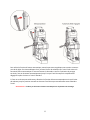
Adjustment of slide and bearing bracket alignment.
An essential requirement of the machine is that the slide can move in a smooth and controlled manner,
free of lateral movement and vibration.
This situation can be maintained by periodic adjustment of the slide and is accomplished in the following
manner:
1. Place the machine in an upright position and, by means of the capstan, raise the slide to its
highest position. Clean the brass gib strips and apply a small amount of light machine oil to the
wear surfaces.
2. Now lower the slide back to its lowest position. Bring the slide into the center of the dovetail
slide housing and loosen screws thus allowing free movement of the arbor support bracket.
3. Commencing with the middle screws, gently feed in all the screws until slight resistance is
encountered.
4. Operate the slide up and down a few times to test the movement and make any further
necessary adjustments. Try to ensure that all the screws are exerting a uniform pressure on the
slide from top to bottom. A perfectly adjusted slide will operate freely up and down without any
sideways movement.
5. Now raise the slide to its highest position. Slightly undo the arbor bearing bracket and, using
fingers only, tighten the screws.
6. Place the machine on a steel plate, connect to power supply and switch on the magnet. Start up
the motor. If the arbor is incorrectly aligned, the arbor support bracket will be seen to oscillate.
Make any necessary further adjustments to the bracket to ensure correct alignment of the
spindle and finally tighten the screws using a spanner. Lastly tighten the arbor bearing bracket.
Check machines grease.
The gearbox grease should be checked once a month to ensure all moving components are covered to
prevent wear. The grease should be changed at least once a year to ensure you gain the best usage from
your machine.
Check Armature of the machine.
This should be checked at least once a month to check that there are no visual signs of damage to the
body or to the commutator. Some signs of wear will be seen on the commutator over a period of time
but this is normal (this is the part that comes into contact with the brushes) however, if there are any
signs of abnormal damage the part should be replaced.

20
17) WARRANTY STATEMENT
Walter warrants its machines to be free from faulty parts, under normal usage of machines, for a
period of 12 months from initial date of purchase. All other parts (excluding cutters) are under
warranty for 90 days, provided that the warranty registration card (or online registration) has been
completed and returned to Walter or its designated distributor within a period of (30) days from the
purchase date. Failure to do so will void the warranty. If the stated is adhered to, Walter will repair or
replace (at its option) without charge any faulty items returned.
This Warranty does not cover:
1. Components that are subject to natural wear and tear caused by the use is not in accordance with
the operator’s instructions
2. Defects in the tool caused by non-compliance with the operating instructions, improper use,
abnormal environment conditions, inappropriate operating conditions overload or insufficient
servicing or maintenance.
3. Defects caused by using accessories, components or spare parts other than original Walter parts.
4. Tools to which changes or additions have been made.
5. Electrical components are subject to manufacturer’s warranty.
Your online registration can be submitted at www.walter.com
The warranty claim must be logged within the warranty period. This requires the submission or sending
of the complete tool in question with the original sales receipt which must indicate the purchase date
of the product. A complaint form must also be submitted prior to the return.
This can be found online at www.walter.com.Failure to complete this form will result in the delay of
your claim. All goods returned defective must be returned pre-paid to Walter, in no event shall
Walter be liable for subsequent direct, or indirect loss or damage.
THIS WARRANTY IS IN LIEU OF ANY OTHER WARRANTY, (EXPRESSED OR IMPLIED) INCLUDING ANY
WARRANTY OF MERCHANTABLITY OR FITNESS FOR A PARTICULAR PURPOSE. WALTER RESERVES THE
RIGHT TO MAKE IMPROVEMENTS AND MODIFICATIONS TO DESIGN WITHOUT PRIOR NOTICE.
“ONLY THE BEST”
La page est en cours de chargement...
La page est en cours de chargement...
La page est en cours de chargement...
La page est en cours de chargement...
La page est en cours de chargement...
La page est en cours de chargement...
La page est en cours de chargement...
La page est en cours de chargement...
La page est en cours de chargement...
La page est en cours de chargement...
La page est en cours de chargement...
La page est en cours de chargement...
La page est en cours de chargement...
La page est en cours de chargement...
La page est en cours de chargement...
La page est en cours de chargement...
La page est en cours de chargement...
La page est en cours de chargement...
La page est en cours de chargement...
La page est en cours de chargement...
La page est en cours de chargement...
La page est en cours de chargement...
La page est en cours de chargement...
La page est en cours de chargement...
La page est en cours de chargement...
La page est en cours de chargement...
La page est en cours de chargement...
La page est en cours de chargement...
La page est en cours de chargement...
La page est en cours de chargement...
La page est en cours de chargement...
La page est en cours de chargement...
La page est en cours de chargement...
La page est en cours de chargement...
La page est en cours de chargement...
La page est en cours de chargement...
La page est en cours de chargement...
La page est en cours de chargement...
La page est en cours de chargement...
La page est en cours de chargement...
La page est en cours de chargement...
La page est en cours de chargement...
La page est en cours de chargement...
La page est en cours de chargement...
La page est en cours de chargement...
La page est en cours de chargement...
La page est en cours de chargement...
La page est en cours de chargement...
La page est en cours de chargement...
La page est en cours de chargement...
La page est en cours de chargement...
La page est en cours de chargement...
-
 1
1
-
 2
2
-
 3
3
-
 4
4
-
 5
5
-
 6
6
-
 7
7
-
 8
8
-
 9
9
-
 10
10
-
 11
11
-
 12
12
-
 13
13
-
 14
14
-
 15
15
-
 16
16
-
 17
17
-
 18
18
-
 19
19
-
 20
20
-
 21
21
-
 22
22
-
 23
23
-
 24
24
-
 25
25
-
 26
26
-
 27
27
-
 28
28
-
 29
29
-
 30
30
-
 31
31
-
 32
32
-
 33
33
-
 34
34
-
 35
35
-
 36
36
-
 37
37
-
 38
38
-
 39
39
-
 40
40
-
 41
41
-
 42
42
-
 43
43
-
 44
44
-
 45
45
-
 46
46
-
 47
47
-
 48
48
-
 49
49
-
 50
50
-
 51
51
-
 52
52
-
 53
53
-
 54
54
-
 55
55
-
 56
56
-
 57
57
-
 58
58
-
 59
59
-
 60
60
-
 61
61
-
 62
62
-
 63
63
-
 64
64
-
 65
65
-
 66
66
-
 67
67
-
 68
68
-
 69
69
-
 70
70
-
 71
71
-
 72
72


Walter ICECUT 250 AUTO Le manuel du propriétaire
- Catégorie
- Outils électroportatifs
- Taper
- Le manuel du propriétaire
dans d''autres langues
Documents connexes
Autres documents
-
Evolution Power Tools EVOMAG28 Guide d'installation
-
PROPOINT 8740144 Le manuel du propriétaire
-
Ega Master 79633 Le manuel du propriétaire
-
Makita HB350 Manuel utilisateur
-
DeWalt DWE1622K Manuel utilisateur
-
Milwaukee 4203 Manuel utilisateur
-
-
-
-
Metabo MAG 32 Mode d'emploi