Makita HB350 Manuel utilisateur

Catégorie
Outils électroportatifs
Taper
Manuel utilisateur
1
A GUIDE TO
GOOD DRILLING PRACTICE
To get the best possible performance from your new Magnec
Drilling Machine, please read this carefully BEFORE using the drill.
Instruc�ons originales
Originele instruc�es
HB350
Magne�c Drilling Machine
WARNING:
For your personal safety, READ and UNDERSTAND before using.
SAVE THESE INSTRUCTIONS FOR FUTURE REFERENCE.
FR
E
S
SNOITCURTSNI LANIGIRO
EN
BEFORE YOU START
To help you get the best possible performance
from your new Magnetic Drilling Machine, this
guide contains simple, sensible pointers for the
safe, effective, and long-term use of the
equipment.
Please read it carefully before using the
drill.
Ensure that you have observed all the general
and specific safety procedures.
Explanation of the pictograms on the
specification plate of the Makita HB350
DANGER!
Indicates an imminent danger or risk to
life and health of a general nature.
ELECTRICAL DANGER!
This means a direct pending danger or
risk to life due to electricity.
CAUTION!
Indicates a possible danger or risk of
slight injury or damage to property.
WEAR EYE & EAR PROTECTORS
Always wear eye and ear protection
when using this drill.
USE SAFETY CHAIN!
For safety reasons securely attach the
tool to the workpiece.
READ THE MANUAL
Read the manual before operating the
machine.
For European Countries Only
WEEE compliance certificate:- on request
All magnetic drilling systems are fully compliant.
with RoHS regulations.
Due to the presence of hazardous components in the
equipment, used electrical and electronic equipment may
have a negative impact on the environment and human
health.
Do not dispose of electrical and electronic appliances
with household waste.
In accordance with the European Directive on waste
Electrical and electronic equipment should be collected
separately and delivered to a separate collection point
for municipal waste, operating in accordance with the
environmental protection regulations.
this is indicated by the symbol of the crossed out
wheeled bin placed on the equipment.
CONTENTS
HB350 Functional Description
The Broach Cutting Concept
General Power Tool Safety Instructions
Optional Accessories
Material and Cutting speeds
Feeds and Speeds
Fitting Safety Guard & Strap and Oil Bottle
Fitting Cutters
Panel Operation
Motor diagram & parts list
Stand diagram & parts list
FR
Instructions françaises
ES
Instrucciones en español
For Canada and the USA only: -
CSAus Declaration of Conformity
We the Makita Corporation as the responsible
manufacturer declare that the following Makita
machine:
Designation of Tool: Magnetic Drilling Machine
Model No./ Type: HB350
conforms to the following Directives:
CAN/CSA-C22.2 No. 745-2-32-95 (R2004)
UL 745-2-32 Ed.1 (R2004) (March 23, 1995)
CAN/CSA-C22.2 No. 745-1-95 (R1999)
UL 745-1Ed.1 (R1995) (March 23, 1995)
EN
HB350 FUNCTIONAL
DESCRIPTION
Cutter capacity - 1.3/8
Chuck Capacity - ½”
No load speed - 850 rpm
Power consumption - 1050w
Clamping force - 8000N (1800lb)
L
x H x W - 8.7/8” x 19.5/16” x 7.11/16
Weight - 26lb
Voltage - 120v
I
NCLUDES
:
Integral coolant system,
Warranty,
Carrying case, Allen keys, Safety strap & Guard
Due to our continuing programme of research and
development, these specifications are subject to change
without notice.
THE BROACH CUTTING CONCEPT
If you are unfamiliar with the use of annular
(or broaching) cutters, take a few minutes to
read this guide - you will benefit from the better
performance and longer life of the tool if you
understand the concept.
Annular cutters only cut material at the
periphery of the hole, rather than converting
the entire hole to shavings. As a result, the time
and energy required to make the hole is lower
than for a traditional twist drill.
The broaching capacity of a machine is
therefore greater than the twist drill capacity.
The slug ejected after the cut also has a higher
scrap value than shavings.
CUTTING TIME
CUTTING TIME
EN
GENRAL POWER TOOL SAFETY INSTRUCTIONS
. INTENDED USE
The intended use of this magnedrill is to drill holes in ferrous metals. The magnet is used to hold
the drill in pe whilst the drill is funoning. It is designed for use in fabn,onstruon,
railways, petrohem and any other applians when drilling ferrous metal.
Any devian from its intended use will not beovered by warranty.
. GENERAL SAFETY RULES
WARNING! Read and understand all instruc�ons. Failure to follow all instruc�ons listed below,
may result in electric shock, re and/or serious personal injury.
SAVE THESE INSTRUCTIONS.
Work area
1.Keep your work area clean and well lit. Cluered benhes and dark areas invite aidents.
2.Do not operate power tools in explosive atmospheres, such as in the presence of ammable
liquids, gases, or dust. Power toolste sparks wh may ignite the dust or fumes.
3.Keep bystanders, children, and visitors away while opera�ng a power tool. Distraonsan
use you to loseontrol
Electrical safety
1.Grounded tools must be plugged into an outlet properly installed and grounded in accordance
with all codes and ordinances. Never remove the grounding prong or modify the plug in any way.
Do not use any adaptor plugs. Check with a qualied electrician if you are in doubt as to whether
the outlet is properly grounded. If the tools should eleally malfunon or break down,
grounding provides a low resistane path toarry eley away from the user.
2.Avoid body contact with grounded surfaces such as pipes, radiators, ranges, and refrigerators.
There is an ineased risk of elesho if your body is grounded.
3.Don’t expose power tools to rain or wet condi�ons. Water entering a power tool will inease
the risk of elesho
4. Do not abuse the cord. Never use the cord to carry the tools or pull the plug from an outlet.
Keep cord away from heat, oil, sharp edges or moving parts. Replace damaged cords
immediately. Damagedords inease the risk of elesho
5. When opera�ng a power tool outside, use an outdoor extension cord marked” W-A” or” W”.
Theseords are rated for outdoor use and redue the risk of elesho
Personal safety
1. Stay alert, watch what you are doing and use common sense when opera�ng a power tool. Do
not use tool while red or under the inuence of drugs, alcohol, or medica�on. A moment of
inanon while operang power tools may result in serious personal injury.
2. Dress properly. Do not wear loose clothing or jewelry. Contain long hair. Keep your hair,
clothing, and gloves away from moving parts. Looseothes, jewelry, or long hair n beaught in
moving parts.
3. Avoid accidental star�ng. Be sure switch is off before plugging in. Carrying tools with your nge
r
on the swh or plugging in tools that have the swh on invites aidents.
4. Remove adjus�ng keys or switches before turning the tool on. A wrenh or a key that is le
EN
aached to a rotang part of the tool may result in personal injury.
5. Do not overreach. Keep proper foond balance at all mes. Proper foong and balance
enable beer control of the tool in unexpected situans.
6. Use safety equipment. Always wear eye protecn. Dust mask, non-skid safety shoes, hardhat,
or hearing pron must be used for appropriate condons.
Tool use and care
1.Use clamps or other pracl way to secure and support the workpiece to a stable plorm.
Holding the work by hand or against your body is unstable and may lead to loss of control.
2.Do not force tool. Use the correct tool for your applicn. The correct tool will do the job
beer and safer at the rate for which it is designed.
3.Do not use tool if switch does not turn it on or o. Any tool that cannot be controlled with the
switch is dangerous and must be repaired.
4.Disconnect the plu from the power source before makin any adjustments, chann
accessories, or storin the tool. Such prevenve safety measures reduce the risk of starng the tool
accidentally.
5.Store idle tools out of reach of children and other untrained persons. Tools are dangerous in the
hands of untrained users.
6.Maintain tools with care. Keep cun tools sharp and clean. Properly maintained tools, with
sharp cung edges are less likely to bind and are easier to control.
7.Check for misalinment or bindin of movin parts, bre of parts, and any other condin
that mayct the tools opern. If damaed, have the tool serviced before usin. Many
accidents are caused by poorly maintained tools.
8.Use only accessories that are recommended by the manufacturer for your model. Accessories
that may be suitable for one tool, maybe come hazardous when used on another tool.
Service
1.Tool service must be performed only by qualied repair personnel. Service or maintenance
performed by unqualied personnel could result in a risk of injury.
2.When servicin a tool, use only idenl replacement parts. Follow instrucns in the
Maintenance secn of this manual. Use of unauthorized parts or failure to follow Maintenance
Instruons may create a risk of electric shock or injury.
EN
Always use safety chain. Mounng can release.
. MAINTENANCE
Occasionally apply a few drops
of oil to the rack toothing.
The bearings of the feed sha
are self- lubricang and must not
be greased.
Grease the sliding surface of the
carriage with MOLYCOTE grease.
When not in use or being
transported the unit should be kept
in the case supplied.
Aer use ensure unit is clean of
swarf and dirt.
Parts that are worn or damaged
should be replaced immediately
with genuine manufacturer’s
replacements.
Ensure all cug edges are
sharp when in operan. Using
blunt cug tools may lead to an
overload of the motor.
Aer every 30 minutes running, it is
recommended that the machine is laid on
its side to permit grease to run across the
gear train.
Aer repeated use, the cradle may
become loose. This is remedied by
adjusng the tension screws on the side
of the body. Put 2.5mm hex wrench into
head of cradle retaining nuts, using 8mm
Spanner undo the locking nuts an-
clockwise, holding the hex wrench without
moving grub screws.
Using the hex wrench gently hten
screws in series un the cradle moves
freely in the slide but does not allow the
motor to wobble.
When adjustment is complete re-
ghten locking nuts clockwise, ensuring
the grub screws do not move from their
new pos
IMPORTANT! – TO PREVENT DAMAGE TO THE CIRCUITRY, NEVER USE
ELECTROMAGNETIC DRILLING MACHINES AND WELDING EQUIPMENT ON THE SAME
WORKPIECE SIMULTANEOUSLY.
Oponal Accessories
For details of opons, either refer to the catalog or inquire at the store of
purchase or a Makita sales oce.
If you need any assistance for more details regarding these accessories, ask your local
Makita Service Center.
HSS Cuer
TCT Cuer
Drill chuck
WARNING!
EN
MATERIAL AND CUTTING SPEEDS
The ease with which material can be
drilled is dependent on several factors
including tensile strength and abrasion
resistance. Whilst hardness and/or
strength is the usual criterion, wide
variations in machinability can exist
among material showing similar physical
properties.
The cutting conditions can be
dependent upon requirements for tool
life and surface finish and further
restricted by the rigidity of the tool and
work piece, lubrication, and machine
power available.
The harder the material the lower
the cutting speed. Some materials of low
hardness contain abrasive constituents
leading to rapid cutting-edge wear at high
speeds. Feed rates are governed by
rigidity of set up, volume of material to be
removed, surface finish and available
machine power.
It is preferable to set and maintain a
constant surface speed (RPM) for a given
material and vary the feed rate within
defined limits.
Machine feed is measured in inches
or millimeters per minute and is the
product of RPM x number of teeth in the
cutter x feed per tooth. Too light or
excessively high feed rates will both cause
premature cutter failure. Heavy feeds on
hard materials will cause chipping of the
cutting edge and excessive heat
generation.
Slender and long shanked cutters
are restricted in feed rate due to
deflection, and wherever possible the
largest and most robust tool must be used.
This is important for harder materials.
Steel up to 400 HB is the potential limit for
conventional M2 HSS tools.
Above 300 HB, cobalt alloy cutters should
be considered for increased tool life. In
softer grades of material, cobalt alloy
cutters may give increased output by
increasing speeds and feed rates by up to
50%. Tungsten Carbide cutters permit
surface speeds and feed rates up to
those for standard cutters.
EN
FEEDS AND SPEEDS
CUTTING SPEEDS
Suggested speed rates for varying cuer sizes/materials
TOOL FEED RATE
(Metric)
MATERIAL
Feed rate (mm/min)
Cuer Diameter (mm)
Cuer Diameter (inches)
ALUMINIUM - 60
BRASS - 45
MILD STEEL - 24
HI TENSILE STEEL - 9
TOOL FEED RATE
(Imperial)
MATERIAL
Feed rate
(inches/min)
ALUMINIUM -
23/8“BRASS - 1 3/4
MILD STEEL - 1
HI TENSILE STEEL -
3/8
PLEASE NOTE
:
These gures are quoted as a starng point. Actual performance will be dictated by material
type, thickness and hardness, applicaon, and cuer condion.
Speed (RPM)
Speed (RPM)
10 706050403020 80
3/8” 3/4” 1.3/16” 1.9/16” 2” 2.3/8” 2.3/4” 3.1/8”
FITTING THE SAFETY GUARD
DRILL GUARD INSTRUCTIONS
Ensure drill unit is isolated from power
supply.
Fit guard to drill as shown.
When drilling, the guard should always be
in contact with the surface being drilled.
As the drill is lowered, the guard will rise
in relation to the drill.
FITTING THE OIL BOTTLE
The cutting oil bottle is held in a sprung
bracket attached to the top of the drill
body. Fit the bracket by removing one of
the cap screws from the top plate and
replace the bolt through the fixing lug on
the bottle bracket, tightening the bolt
enough to allow some radial movement of
the bracket. The coolant tube is a push fit
into the self-seal gland at the base of the
tap and a similar fitting on the lower
arbor bracket.
FITTING THE SAFETY CHAIN
A safety chain should be used wherever
possible as a safety precaution in the event
of a power failure releasing the magnet;
particularly in situations where the machine
is clamped onto a vertical surface or in an
inverted position.
SAFETY CHAIN INSTRUCTIONS
When the machine has been clamped to
the workpiece in the correct position for
drilling, the chain should be fitted at a
secure part of the drill. Then passed
around a substantial part of the
workpiece and fastened securely.
Once the cut is complete, the chain
should be released, and the machine
supported before the magnet is
disengaged.
FITTING THE CUTTER
Insertion of pilot pin
The pilot pin is used to both center the cutter and
to eject the slug on completion of the cut. It has a
flat side to allow coolant to run down to reach the
center of the cut where the heat is greatest. Slide
the pin through the hole in the center of the cutter
shank.
FITTING THE CUTTER
Fig 1.
To insert the cutter in the arbor, first loosen the grub
screws, using an M5 hexagonal wrench. Ensure the grub
screws are sufficiently loose enough to allow the shank of
the cutter to enter freely.
Fig 2.
Ensure the drive flats on the cutter shank are fully aligned
with the two grub screws in the machine arbor.
Fig 3.
Ensuring the shank of the cutter is fully inserted inside the
arbor, tighten the grub screws fully to give the cutter a
secure fitting inside the arbor.
Fig 4.
The cutter is now ready for use.
APPLYING COOLANT
Cutting oil ensures longer cutter life and enables
the slug to be ejected cleanly. A 500 ml bottle is
included with every machine.
Oil will be automatically delivered to the cutter
when the cut commences.
When cutting on vertical surfaces or upside down,
cutting paste, gel or foam is recommended. It is best
applied inside the cutter before drilling.
Plug the machine into the power socket and the
red LED on the electronic control panel will flash.
N.B. Safety strap and guards have been omitted from the photo’s for clarity.
Fig. 1
Fig. 2
Fig. 3
Fig. 4
Fig. 4
Fig. 3
OPERATION
HB350 MOTOR PARTS
Nr.
Description
Qty
Part No
1
CARBON BRUSH ASSY. 6.3X10X18
2
EBD002
2
BRUSH HOLDER ASSY.
2
EBD001
3
SCREW M4 X 12
2
EBD003
4
SPRING WASHER M4
2
EBD004
5
PHILIPS HEAD SELF-TAP SCREW 4.8X45
4
EBD005
6
BACK COVER
1
EIB527
7
FIELD COIL CASING
1
EIB526
8
FIELD COIL ASSY 110V
1
EBD008-A
FIELD COIL ASSY 230V
1
EBD008-B
9
PHILIPS HEAD SELF - TAP SCREW 3.9X60
2
EBD009
10
BAFFE
1
EBD010
11
O RING
1
EBD011
12
BALL BEARING (8-22-7) 608 2Z
3
UDC022
13
DUST WASHER
1
EBD012
14
ARMATURE ASSY 110V
1
EBD013-A
ARMATURE ASSY 230V
1
EBD013-B
15
CIRCLIP 28MM X 1.2 B TYPE
1
EBD014
16
BALL BEARING (12-28-8) 6001 2Z
1
UDC023
17
GEAR CASE COVER
1
EBD015
18
CIRCLIP 10MM X 1 A TYPE
1
EBD016
19
GASKET
1
EBD017
20
INTER SHAFT ASSY.
1
EBD018
21
SPINDLE GEAR
1
EBD019
22
BALL BEARING (17-35-10) 6003 2RS
1
UDC004
23
OIL SEAL 20-30-7 B TYPE
2
EBD020
24
GEAR CASE
1
EBD021
25
PHILIPS HEAD SELF-TAP SCREW 4.8 X 60
4
EBD022
26
BALL BEARING 6904 2RS
1
EBD025
27
ARBOR BODY.
1
EIB528
28
ARBOR SPRING
1
EBD026
29
ARBOR EJECTION PLUG
1
EBD027
30
ARBOR WASHER
1
EBD028
31
ARBOR RUBBER WASHER
1
EBD029
32
ARBOR CIRCLIP
1
EBD030
33
CARBON BRUSH WASHER
2
EBD031
34
CARBON BRUSH FIXING SCREW
2
EBD032
35
PG9 PUSH FIT GLAND
1
40025
36
MOTOR LOCATING KEY
1
M1019
HB350 STAND PARTS
Nr.
Description
Qty
Part No
1
CONDUIT (large dia 12mm) - PMA-PCLT-10B.50
1
M0443
2
M6 X 16 CAP HEAD SCREW
3
SC616CAP
3
SLIDE HB350 MAKITA
1
M1000
4
M6 X 25 CAP HEAD SCREW
7
SC625CAP
5
HANDLE KNOB (10mm KNOCK ON)
3
M0841
6
10MM X 130MM HANDLE (SMALL)
3
BD043
7
M4 X 6 BUTTON HEAD SCREW
8
SC46BUT
8
WARNING PLATE MAKITA HB350 CE JAPAN
CE JAPANMAKITA HB350 CE JAPAN
MAKITA HB350 CE JAPAN
M1002
WARNING PLATE MAKITA HB350 CE BELGIUM
BELGIUM
M1003
WARNING PLATE MAKITA HB350 CSA JAPAN
M1014
WARNING PLATE MAKITA HB350 UKCA UK
M1018
WARNING PLATE MAKITA HB350 RCM AUSTRALIA
M1021
9
25A - BRIDGE RECTIFIER (395-4310)
1
M0401
10
M5 X 16 CAP HEAD SCREW
3
SC516CAP
11
OILFEED TOP BRACKET - (MB30 BODY)
1
M0811A
12
BRASS RAIL (MB30)
2
M0101
13
RACK (MB30)
1
M0831
14
OIL CUP RETAINING CLIP COMPLETE
1
10076C
15
M5 NYLOC
6
10085B
16
M5X25 KNURLED POINT GRUB SCREW
5
10085A
17
CAPACITOR
1
RD43118
18
BUSH (PINION) - 33 X 28 X 20 OILITE BUSH
2
M0081
19
PINION END CAP - DEEP
1
M0072
20
O CLIP 8-11 BOCLIP8/11
1
RD47179
21
D5000 OIL CUP ASSEMBLY
1
30046A
22
U-06040(30MC) 6MM X 4MM CLEAR POLYURETHANE TUBE
1
BD029
23
MAKITA HB350 CONTROL PANEL PLATE
1
M1001
24
M16 PUSH FIT GLAND - PMA BVND-M160GT
1
40026
25
MB30 BODY BLACK
1
M0001BLK
26
M16 PIGTAIL GLAND COMPLETE WITH LOCK NUT - BBSM 16
1
10231
27 USA CABLE - 14 GAUGE - 3M - AB-CAB-870
C
ABL03
EUROPEAN CABLE C/W MOULD PLUG - AB-CAB-876 - 3M
C
ABL04
MAKITA BRAZIL CABLE C/W PLUG 220V - 3M
C
ABL05
3MTR-110V MAINS LEAD BLACK C/W IND PLUG
C
ABL06
ARGENTINA CABLE C/W PLUG - 230V - 3M
C
ABL08
AUS/NZ-3M MAINS CABLE C/W MOULDED PLUG-AB-CAB-866
CABL09
28
M8 WASHER FOR ARBOR INTERNAL
1
RD47187
29
M4 BRASS NUT
1
NUT-M4-B
30
HB350 MAGNET BASE
1
M1020
31
M4 X 6 SLOTTED CSK MC SCREW - BZP
5
SC46CSK
32
M4 X 12 CSK MC SCREW - BRASS
1
SC412CSK-B
33
M4 SHAKE PROOF WASHER-BZP-WSH-227-004-ZC221
9
SPWR-M4
34
PINION - (SMALL)
1
M0041
35
EIBENSTOCK BHM35 DRILL UNIT - 110V MAKITA BLUE
EIB522
EIBENSTOCK BHM35 DRILL UNIT - 230V MAKITA BLUE
EIB523
36
DRILL STOP/START SWITCH - 110V - KJD17F/120V/50HZ -
KJD17-P2-F2-V1-M2-A1
NCP001
DRILL STOP/START SWITCH - 230V - KJD17F-230V-50HZ-
KJD17F-P2-F2-V3-M2-A1
NCP002
37
MAGNET SWITCH - NCP PANEL - B418CG00000
1
NCP006
38
G.F.S. (MB30)
1
M0441
39
1/8 BSP-6MM BLACK PUSH FIT
1
50015
40
GUARD TO SUIT NEW UNI 1 MBQ35N/EQ35N/EBM35
1
VISO18
41
318-565 VARISTOR (V150LA10A)
W18XC522
VARISTOR HIGHSURGE 20MM 275 VRMS
W18XC521
42
248-447 FUSE HOLDER
1
W18XC511
43
2A FUSE (RAPID 26-2469)
1
W18XC512
44
WASHER SMBK1869836HPU
1
UOD009
FR
AVANT
COMMENCER
Pour vous aider à er le meilleur par de votre
nouvelle perceuse magnéque, ce guide donne des
conseils simples et judicieux pour assurer une
usan sûre, ecace et durable de l'équipement.
Veuillez lire envement ce qui suit avant d'user
la perceuse.
Assurez-vous de respecter toutes les produres de
sécurité générales et spéciques.
Explicaon des pictogrammes gurant sur la plaque
signaléque de la perceuse Makita HB350
DANGER !
Indique un danger ou un risque imminent
relaf à la survie et à la santé de manière
générale.
DANGER ÉLECTRIQUE !
Indique un danger ou un risque imminent
ou direct relaf à la survie et dû à
l'électricité.
ATTENTION !
Indique un danger ou un risque éventuel de
blessure légère ou d'endommagement de
l'équipement.
PORTER DES PROTECTIONS OCULAIRES
ET AUDITIVES
Portez toujours des protecons oculaires et
audives lorsque vous ulisez cee perceuse.
UTILISER LA CHAÎNE DE SÉCURITÉ !
Pour des raisons de sécurité, xez solidement
l'ou à la pièce.
LIRE LE MANUEL
Lisez le manuel avant d'uliser la machine.
Pour les pays européens uniquement
Cercat de conformité DEEE : sur demande
Tous les systèmes de perçage magnéque sont enèrement conformes à la
réglementaon RoHS.
En raison de la présence de composants dangereux, les équipements
électriques et électroniques usagés peuvent avoir un impact négaf sur
l'environnement et la santé humaine.
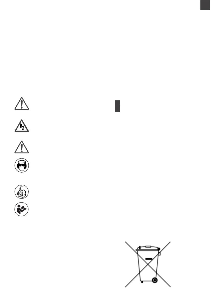
Ne jetez pas les appareils électriques et électroniques avec les ordures
ménagères.
Conformément à la direcve européenne sur les déchets, les équipements
électriques et électroniques doivent être collectés séparément et amenés dans
un point de collecte disnct pour les déchets municipaux, en vertu des
réglementaons de protecon de l'environnement.
Ceci est indiqué par le symbole de poubelle barrée gurant sur l'équipement.
SOMMAIRE
Descripn fonconnelle de la perceuse HB350
Le concept de coupe à la broche
Instrucons générales de sécurité pour les ous
électriques
Accessoires en opon
Matériaux et vitesses de coupe
Avances et vitesses
Installaon d'une protecn, d'une sangle de
sécurité et d'un acon d'huile
Installaon des fraises
Foncnnement du panneau
Schéma et liste de pièces du moteur
Schéma et liste de pièces détachées
FR Instrucons françaises
ES Instrucciones en español
Pour le Canada et les États-Unis uniquement : -
Déclaraon de conformité CSAus
Nous soussignés, Makita Corporaon, en tant que
fabricant responsable, déclarons que la machine Makita
suivante :
Désignaon de l'oul : Perceuse magnéque
Référence/Type : HB350
est conforme aux Direcves suivantes :
CAN/CSA-C22.2 No. 745-2-32-95 (R2004)
UL 745-2-32 Ed.1 (R2004) (23 mars 1995)
CAN/CSA-C22.2 No. 745-1-95 (R1999)
UL 745-1Ed.1 (R1995) (23 mars 1995)
DE
FR
DESCRIPTION FONCTIONNELLE DE LA
PERCEUSE HB350
Capacité de coupe - 1,3/8"
Capacité du mandrin - ½"
Vitesse à vide - 850 tr/min
Consommation d'énergie - 1 050 w
Force de serrage - 8 000 N (1 800 lb)
L x H x l - 8,7/8" x 19,5/16" x 7,11/16"
Poids - 26 lb
Tension - 120 V
INCLUT : Système de refroidissement intégré, garantie, boîtier
de transport, clés Allen, sangle de sécurité et protection
En raison de notre programme continu de recherche et de
développement, ces spécifications sont susceptibles d'être modifiées
sans préavis.
LE CONCEPT DE COUPE À LA BROCHE
Si vous n'êtes pas familiarisé avec l'utilisation de
fraises à carotter (ou à brocher), prenez quelques
minutes pour lire ce guide. Vous atteindrez de
meilleures performances et une plus longue durée de
vie de l'outil si vous comprenez le concept.
Les fraises à carotter ne coupent le matériau qu'à la
périphérie du trou, plutôt que de transformer le trou
entier en copeaux. Par conséquent, le temps et
l'énergie nécessaires pour réaliser le trou sont moins
importants qu'avec un foret hélicoïdal traditionnel.
La capacité de brochage d'une machine est donc
supérieure à la capacité d'un foret hélicoïdal. Le
fragment indésirable éjecté après la coupe présente
également une valeur de rebut plus importante que
les copeaux.
PUISSANCE
REQUISE
MATÉRIAU
RETIRÉ
TEMPS DE COUPE
TEMPS DE COUPE
FR
INSTRUCTIONS GÉNÉRALES DE SÉCURITÉ POUR LES OUTILS ÉLECTRIQUES
. UTILISATION PRÉVUE
Cette perceuse magnétique est conçue pour percer des trous dans des métaux ferreux. La partie
magnétique sert à maintenir la perceuse en place pendant le fonctionnement. La perceuse est conçue
pour être utilisée dans la fabrication, la construction, les chemins de fer, la pétrochimie et toute autre
application de perçage de métaux ferreux.
Les écarts par rapport à l'utilisation prévue ne sont pas couverts par la garantie.
. RÈGLES GÉNÉRALES DE SÉCURITÉ
AVERTISSEMENT ! Assurez-vous de lire et comprendre l'ensemble des instructions. Le non-respect des
instructions énumérées ci-dessous peut entraîner un choc électrique, un incendie et/ou des blessures
corporelles graves.
CONSERVEZ CES INSTRUCTIONS.
Zone de travail
1.Gardez la zone de travail propre. Les zones encombrées et sombres sont propices aux accidents.
2.N'utilisez pas d'outils électriques dans des atmosphères explosives, par exemple en présence de
liquides, de gaz ou de poussières inflammables. Les outils électriques créent des étincelles susceptibles
d'enflammer les poussières ou les fumées.
3.Éloignez tout individu, enfant ou visiteur lorsque vous utilisez un outil électrique. Les distractions
peuvent vous faire perdre le contrôle
Sécurité électrique
1.Les outils mis à la terre doivent être branchés sur une prise de courant installée et mise à la terre
conformément à tous les codes et règlements applicables. Ne retirez jamais la broche de mise à la terre
et ne modifiez jamais la prise de quelque manière que ce soit. N'utilisez pas de prises d'adaptation. En
cas de doute, consultez un électricien qualifié pour savoir si la prise de courant est correctement mise à
la terre. En cas de dysfonctionnement ou de panne électrique de l'outil, la mise à la terre offre un chemin
de faible résistance pour éloigner l'électricité de l'utilisateur.
2.Évitez tout contact entre votre corps et des surfaces mises à la terre telles que les tuyaux, les
radiateurs, les cuisinières et les réfrigérateurs. Le risque de choc électrique est plus élevé si votre corps
est mis à la terre.
3.N'exposez pas les outils électriques à la pluie ou à l'humidité. L'eau qui pénètre dans un outil électrique
augmente le risque de choc électrique.
4. Utilisez correctement le câble. Ne tenez jamais l'outil par le câble et ne tirez jamais sur le câble pour
débrancher l'outil d'une prise. Éloignez le câble des sources de chaleur, de l'huile, des arêtes vives ou
des pièces mobiles. Remplacez immédiatement les câbles endommagés. Les câbles endommagés
augmentent le risque de choc électrique.
5. Lorsque vous utilisez un outil électrique à l'extérieur, utilisez une rallonge extérieure portant
l'inscription "W-A" ou "W". Ces rallonges sont conçues pour une utilisation en extérieur et réduisent le
risque de choc électrique.
Sécurité personnelle
1. Restez vigilant, prêtez attention à votre travail et faites preuve de bon sens lorsque vous utilisez un
outil électrique. N'utilisez pas d'outils lorsque vous êtes fatigué ou sous l'influence de drogues, d'alcool
ou de médicaments. Lors de l'utilisation d'un outil électrique, un seul moment d'inattention peut
entraîner des blessures graves.
2. Habillez-vous correctement. Ne portez pas de vêtements amples ou de bijoux. Attachez vos cheveux
s'ils sont longs. N'approchez pas vos cheveux, vos vêtements et vos gants des pièces mobiles. Les
vêtements amples, les bijoux ou les cheveux longs peuvent se coincer dans les pièces mobiles.
FR
3. Évitez tout démarrage accidentel. Assurez-vous que l'interrupteur est en position d'arrêt avant de
brancher l'outil. Le fait de tenir un outil avec le doigt sur l'interrupteur ou de brancher un outil dont
l'interrupteur est en position de marche est propice aux accidents.
4. Retirez les clés de réglage ou les clés à molette avant de mettre l'outil en marche. Une clé de réglage
ou une clé à molette qui reste fixée à une partie rotative de l'outil peut entraîner des blessures.
5. N'utilisez pas l'outil en vous penchant trop en avant. Gardez toujours un bon équilibre et les deux
pieds au sol. Un bon équilibre permet de mieux contrôler l'outil dans des situations inattendues.
6. Utilisez des équipements de sécurité. Portez toujours une protection oculaire. Selon les conditions, il
convient d'utiliser un masque anti-poussière, des chaussures de sécurité antidérapantes, un casque ou
une protection auditive.
Utilisation et entretien de l'outil
1. Utilisez des pinces ou tout autre élément pratique pour fixer la pièce à usiner à une plateforme stable
et pour la soutenir. Le soutien de la pièce à la main ou contre votre corps n'est pas suffisant et peut
entraîner une perte de contrôle.
2.Ne forcez pas sur l'outil. Utilisez l'outil approprié à votre application. L'outil approprié fonctionnera
mieux et de manière plus sûre au rythme pour lequel il a été conçu.
3.N'utilisez pas l'outil si l'interrupteur ne permet pas de le mettre en marche et de l'éteindre. Les outils
qui ne peuvent pas être contrôlés au moyen de l'interrupteur sont dangereux et doivent être réparés.
4.Débranchez la prise de la source d'alimentation avant d'effectuer des réglages, de changer
d'accessoires ou de ranger l'outil. Ces mesures préventives de sécurité réduisent le risque de démarrage
accidentel de l'outil.
5.Rangez les outils inutilisés hors de portée des enfants et des personnes non qualifiées. Les outils sont
dangereux entre les mains d'utilisateurs non qualifiés.
6.Entretenez les outils avec soin. Gardez les outils de coupe bien aiguisés et propres. Les outils
correctement entretenus et dont les arêtes de coupe sont tranchantes sont moins susceptibles de se
bloquer et plus faciles à contrôler.
7.Vérifiez qu'aucune pièce mobile n'est mal alignée, grippée ou brisée et assurez-vous qu'aucun autre
problème ne risque d'affecter le fonctionnement de l'outil. Si l'outil est endommagé, faites-le entretenir
avant de l'utiliser. De nombreux accidents sont provoqués par des outils mal entretenus.
8.N'utilisez que les accessoires recommandés par le fabricant pour votre modèle. Les accessoires
adaptés à un certain outil peuvent être dangereux s'ils sont utilisés avec un autre outil.
Entretien
1.L'entretien de l'outil ne doit être effectué que par un personnel qualifié. Si l'entretien ou la
maintenance est effectué par un personnel non qualifié, cela peut entraîner un risque de blessure.
2.Lors de l'entretien d'un outil, n'utilisez que des pièces de rechange identiques. Suivez les instructions
de la section « Entretien » de ce manuel. L'utilisation de pièces non autorisées ou le non-respect des
instructions d'entretien peut entraîner un risque de choc électrique ou de blessure.
FR
AVERTISSEMENT !
Utilisez toujours la chaîne de sécurité. L'installation peut se relâcher.
. ENTRETIEN
Appliquez de temps en temps
quelques gouttes d'huile sur la denture
de la crémaillère.
Les roulements de l'arbre d'avance
sont autolubrifiants et ne doivent pas
être graissés.
Lubrifiez la surface de glissement du
chariot avec de la graisse MOLYCOTE.
Lorsqu'il n'est pas utilisé ni transporté,
l'appareil doit être conservé dans le
boîtier fourni.
Après l'utilisation, assurez-vous que
l'appareil est exempt de copeaux et de
saletés.
Les pièces usées ou endommagées
doivent être remplacées immédiatement
par des pièces de rechange d'origine du
fabricant.
Assurez-vous que toutes les arêtes de
coupe sont bien aiguisées pendant le
fonctionnement. L'utilisation d'outils de
coupe émoussés peut entraîner une surcharge
du moteur.
Toutes les 30 minutes de fonctionnement, il
est recommandé de coucher la machine sur le
côté pour permettre à la graisse de circuler dans
le train d'engrenages.
Après une utilisation répétée, le berceau peut
se desserrer. Il est possible d'y remédier en
réglant les vis de tension sur le côté du corps.
Placez une clé hexagonale de 2,5 mm dans la
tête des écrous de retenue du berceau et, à
l'aide d'une clé de 8 mm, tournez les contre-
écrous dans le sens antihoraire, en tenant la c
hexagonale sans déplacer les vis sans tête.
À l'aide de la clé hexagonale, serrez doucement
les vis en série jusqu'à ce que le berceau se
déplace librement dans la glissière mais ne
permette pas au moteur d'osciller.
Une fois l'ajustement terminé, resserrez les
contre-écrous dans le sens horaire, en vous
assurant que les vis sans tête restent fixées dans
leur nouvelle position
IMPORTANT ! POUR ÉVITER D'ENDOMMAGER LES CIRCUITS, N'UTILISEZ JAMAIS SIMULTANÉMENT UNE
PERCEUSE ÉLECTROMAGNÉTIQUE ET UN ÉQUIPEMENT DE SOUDAGE SUR LA MÊME PIÈCE.
  • Page 1 1
  • Page 2 2
  • Page 3 3
  • Page 4 4
  • Page 5 5
  • Page 6 6
  • Page 7 7
  • Page 8 8
  • Page 9 9
  • Page 10 10
  • Page 11 11
  • Page 12 12
  • Page 13 13
  • Page 14 14
  • Page 15 15
  • Page 16 16
  • Page 17 17
  • Page 18 18
  • Page 19 19
  • Page 20 20
  • Page 21 21
  • Page 22 22
  • Page 23 23
  • Page 24 24
  • Page 25 25
  • Page 26 26
  • Page 27 27
  • Page 28 28
  • Page 29 29
  • Page 30 30
  • Page 31 31
  • Page 32 32
  • Page 33 33
  • Page 34 34
  • Page 35 35
  • Page 36 36
  • Page 37 37
  • Page 38 38
  • Page 39 39
  • Page 40 40
  • Page 41 41
  • Page 42 42
  • Page 43 43
  • Page 44 44

Makita HB350 Manuel utilisateur

Catégorie
Outils électroportatifs
Taper
Manuel utilisateur

dans d''autres langues