
IMPORTANT: IMPORTANT : IMPORTANTE:
Read Before Using Lire avant usage Leer antes de usar
Operating/Safety Instructions
Consignes de fonctionnement/sécurité
Instrucciones de funcionamiento y seguridad
GPL5
For English Version Version française Versión en español
See page 4 Voir page 15 Ver la página 26
1-877-BOSCH99 (1-877-267-2499) www.boschtools.com
Call Toll Free for
Consumer Information
& Service Locations
Pour obtenir des informations
et les adresses de nos centres
de service après-vente,
appelez ce numéro gratuit
Llame gratis para
obtener información
para el consumidor y
ubicaciones de servicio
GPL 5
GPL5 manual-3_REV3:Bosch 10/26/11 6:48 PM Page 1

-2-
GPL
5
G
PL 5
G
P
L
5
1 1/4”
(32 mm)
3/4”
(20 mm)
1 3/4”
(45 mm
)
1 1/4”
(32 mm)
2 3/4”
(32 mm)
G
P
L
5
3
6
0
1
K6
6
2
1
0
R
o
b
e
r
t
Bos
ch
T
o
o
l
C
o
rp
.
M
o
u
nt
Pr
o
s
p
e
ct
, I
L
M
a
d
e
in
C
h
ina
1
7
7
5
1
1
1
6
7
1
2
3
4
1
11
12
8
13
14
10
12
9
17
15
GPL5 manual-3_REV3:Bosch 10/26/11 6:48 PM Page 2

Read all instructions. Failure to
follow all instructions listed
below may result in hazardous radiation
exposure, electric shock, fire and/or serious
injury. The term “tool” in all of the warnings listed
below refers to your mains-operated (corded) tool
or battery-operated (cordless) tool.
The following labels are on
your laser tool for your
convenience and safety. They indicate where
the laser light is emitted by the tool. ALWAYS
BE AWARE of their location when using the
tool.
Do not direct the laser beam at persons or animals and do not stare into the
laser beam yourself. This tool produces laser class II laser radiation and
complies with 21 CFR 1040.10 and 1040.11 except for deviations pursuant to
Laser Notice No. 50, dated June 24, 2007. This can lead to persons
being blinded.
Changes or modifications to this equipment not expressly approved by the party responsible
for compliance could void the user's authority to operate the equipment.
Use of controls or adjustments or performance of procedures other than
those specified herein may result in hazardous radiation exposure.
DO NOT remove or deface any warning or caution labels. Removing labels increases the risk
of exposure to laser radiation.
Use of controls or adjustments or performance of procedures other than those specified in this
manual, may result in hazardous radiation exposure.
ALWAYS make sure that any bystanders in the vicinity of use are made aware of the dangers
of looking directly into the laser tool.
DO NOT place the laser tool in a position that may cause anyone to stare into the laser beam
intentionally or unintentionally. Serious eye injury could result.
ALWAYS position the laser tool securely. Damage to the laser tool and/or serious injury to the
user could result if the laser tool fails.
ALWAYS use only the accessories that are recommended by the manufacturer of your laser
tool. Use of accessories that have been designed for use with other laser tools could result in
serious injury.
DO NOT use this laser tool for any purpose other than those outlined in this manual. This could
result in serious injury.
DO NOT leave the laser tool “ON” unattended in any operating mode.
DO NOT disassemble the laser tool. There are no user serviceable parts inside. Do not
modify the product in any way. Modifying the laser tool may result in hazardous laser
radiation exposure.
DO NOT use the laser viewing glasses as safety goggles. The laser viewing glasses are used
for improved visualization of the laser beam, but they do not protect against laser radiation.
DO NOT use the laser viewing glasses as sun glasses or in traffic. The laser viewing glasses
do not afford complete UV protection and reduce color perception.
DO NOT use any optical tools such as, but not limited to, telescopes or transits to view the
laser beam. Serious eye injury could result.
DO NOT stare directly at the laser beam or project the laser beam directly into the eyes of
others. Serious eye injury could result.
SAVE THESE INSTRUCTIONS
-3-
General Safety Rules
!
WARNING
!
WARNING
!
CAUTION
GPL5 manual-3_REV3:Bosch 10/26/11 6:48 PM Page 3

Work area safety
Keep work area clean and well lit.
Cluttered or dark areas invite accidents.
DO NOT operate the laser tool around
children or allow children to operate the
laser tool. Serious eye injury could result.
Electrical safety
Batteries can explode or
leak, cause injury or fire.
To reduce this risk, always follow all
instructions and warnings on the battery label
and package.
DO NOT short any battery terminals.
DO NOT charge alkaline batteries.
DO NOT mix old and new batteries. Replace
all of them at the same time with new
batteries of the same brand and type.
DO NOT mix battery chemistries.
Dispose of or recycle batteries per
local code.
DO NOT dispose of batteries in fire.
Keep batteries out of reach of children.
Remove batteries if the device will not be
used for several months.
Personal safety
Stay alert, watch what you are doing and
use common sense when operating a
tool. Do not use a tool while you are tired
or under the influence of drugs, alcohol
or medication. A moment of inattention
while operating a tool may result in serious
personal injury or incorrect
measurement results.
Use safety equipment. Always wear eye
protection. Safety equipment such as dust
mask, non-skid safety shoes, hard hat, or
hearing protection used for appropriate
conditions will reduce personal injuries.
Multiple-Purpose Attachment
Keep the multiple-purpose
attachment 8 away from
cardiac pacemakers. The
magnets 12 generate a field
that can impair the function of
cardiac pacemakers.
• Keep the multiple-purpose attachment
8 away from magnetic data medium and
magnetically-sensitive equipment. The
effect of the magnets 12 can lead to
irreversible data loss.
Use and care
Use the correct tool for your application.
The correct tool will do the job better
and safer.
Do not use the tool if the switch does not
turn it on and off. Any tool that cannot be
controlled with the switch is dangerous and
-4-
!
WARNING
FCC Statement
This device complies with part 15 of the FCC Rules. Operation is subject to the following
two conditions: (1) This device may not cause harmful interference, and (2) this device
must accept any interference received, including interference that may cause undesired
operation.
Changes or modifications to this unit not expressly approved by the
party responsible for compliance could void the user's authority to
operate the equipment.
Note: This equipment has been tested and found to comply with the limits for a Class B
digital device, pursuant to part 15 of the FCC Rules. These limits are designed to
provide reasonable protection against harmful interference in a residential installation.
This equipment generates, uses and can radiate radio frequency energy and, if not
installed and used in accordance with the instructions, may cause harmful interference
to radio communications. However, there is no guarantee that interference will not occur
in a particular installation. If this equipment does cause harmful interference to radio or
television reception, which can be determined by turning the equipment off and on, the
user is encouraged to try to correct the interference by one or more of the following
measures:
- Reorient or relocate the receiving antenna.
- Increase the separation between the equipment and receiver.
- Connect the equipment into an outlet on a circuit different from that to which the
receiver is connected.
- Consult the dealer or an experienced radio/TV technician for help.
!
WARNING
GPL5 manual-3_REV3:Bosch 10/26/11 6:48 PM Page 4

-5-
must be repaired.
Store idle tool out of the reach of children
and do not allow persons unfamiliar with
the tool or these instructions to operate
the tool. Tools are dangerous in the hands
of untrained users.
Maintain tools. Check for misalignment or
binding of moving parts, breakage of
parts and any other condition that may
affect the operation. If damaged, tool
must be repaired by the authorized Bosch
service center before further use. Many
accidents are caused by poorly maintained
tools.
Use the tool, accessories, etc., in
accordance with these instructions and in
the manner intended for the particular
type of tool, taking into account the
working conditions and the work to be
performed. Use of the tool for operations
different from those intended could result in a
hazardous situation.
Service
Have your tool serviced by a qualified
repair person using only identical
replacement parts. This will ensure that the
safety of the tool is maintained.
Develop a periodic maintenance schedule
for tool. When cleaning a tool be careful
not to disassemble any portion of the tool
since internal wires may be misplaced or
pinched or may be improperly mounted.
Certain cleaning agents such as gasoline,
carbon tetrachloride, ammonia, etc. may
damage plastic parts.
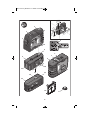
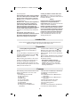
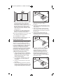
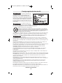
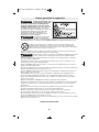
The numbering of the product features shown
refers to the illustration of the tool on the
graphic page.
1 Exit opening for laser beam
2 Latch of battery lid
3 Battery lid
4 On/Off switch
5 Laser warning label
6 Tripod mount 5/8-11
7 Serial number
8 Multi-Purpose Attachment
9 Locking screw for Multi-Purpose
Attachment
10 Screw holes of Multi-Purpose Attachment
11 Opening for strap attachment
12 Magnets
13 1/4-20 tripod mount on Multi-Purpose
Attachment
14 5/8-11 tripod mount on Multi-Purpose
Attachment
15 Measurement plate with stand*
16 Protective Case “not shown”
17 Laser viewing glasses
18 Tripod*
*The accessories illustrated or described are
not included as standard delivery.
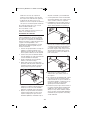
Inserting/Replacing the Battery
Alkaline batteries are recommended for
the tool.
To open the battery compartment 3, turn the
latch 2 in clockwise direction to position
and pull off the battery lid. Insert the
batteries provided.
When inserting, pay attention to the correct
polarity according to the representation on
the inside of the battery compartment.
Position the battery lid to the bottom of the
housing and then push it upward. To lock the
battery lid, turn the latch 2 in
counterclockwise direction to the position.
When the laser beams flash slowly during
operation,the batteries are low. When the
flashing begins, the tool can be operated for
approx. 8 h.
Always replace all batteries at the same time.
Only use batteries from one brand and with
the identical capacity.
• Remove the batteries from the
tool when not using it for extended
periods. When storing for extended
periods, the batteries can corrode and
discharge themselves.
This tool projects plumb and horizontal points and is intended for accurate transfer and
alignment of plumb, level, graded and 90-degree points
Intended Use
Preparation
Features
GPL5 manual-3_REV3:Bosch 10/26/11 6:48 PM Page 5

-6-
Initial Operation
• Protect the tool against moisture and
direct sun irradiation.
• Do not subject the tool to extreme
temperatures or variations in
temperature.
As an example, do not leave it in vehicles
for longer periods. In case of large
variations in temperature, allow the
tool to adjust to the ambient temperature
before putting it into operation. In case of
extreme temperatures or variations in
temperature, the accuracy of the tool can
be impaired.
• Avoid heavy impact or falling of the
tool. After heavy exterior impact on the
tool, an accuracy check should always be
carried out before continuing to work (see
“Leveling Accuracy”). Do not use the tool
when the laser emitting cover has been
damaged after heavy exterior impact on
the tool. Many accidents are caused by
poorly maintained tools.
• Switch the tool off during transport.
When switching off, the leveling unit,
which can be damaged in case of intense
movement, is locked.
Switching On and Off
To switch on the tool, push the On/Off
switch 4 forward so that “I” is indicated on
the switch. Immediately after switching on,
the tool sends a laser beam out of each exit
opening 1.
• Do not point the laser beam at persons
or animals and do not look into the
laser beam yourself, not even from a
large distance.
To switch off the tool, push the On/Off
switch 4 backward so that “0” is indicated on
the switch. When switching off, the leveling
unit is locked.
Setting the Automatic Switch-off
By default, the tool automatically shuts off 20
minutes after being switched on. The
automatic switch-off can be set from 20
minutes to 8 hours. For this, switch the tool
on, then immediately off, and then on again
within 4 s. To confirm the change, all laser
beams will flash quickly for 2 s after
switching on the second time.
• Do not leave the switched on tool
unattended and switch the tool off after
use. Other persons could be blinded by the
laser beam. When switching on the tool the
next time, the automatic switch-off is set to
20 minutes again.
Working with Automatic Leveling
Position the tool on a level and firm support,
attach it to the holder 8 or to the tripod 18.
After switching on, the automatic leveling
function automatically compensates
irregularities within the self-leveling range
from ±5° (longitudinal axis) and ±3° (lateral
axis). The leveling is finished as soon as the
laser points do not move any more.
If the automatic leveling function is not
Operation
Working range (typical) 100 ft (30m)
Leveling Accuracy
Minimum Factory
Accuracy +/- 0.3mm/m (0.0036in/ft)
Typical Accuracy up to 1/4 at 100 ft
Self-leveling range (typical) alongside the
– longitudinal axis up to ±5°
– lateral axis ±3°
Operating temperature 14 °F... 104 °F
(–10 °C ... +40 °C)
Storage temperature -4 °F... 158 °F
( –20 °C ... +70 °C)
Relative air humidity, max. 90 %
Laser class 2
Laser type 635 nm, <1 mW
Tripod mount 5/8-11
Batteries 4 x 1.5 V LR6 (AA)
Operating lifetime, approx. 24 h
Weight according to EPTA-Procedure
01/2003 1.6lb (725g)
Dimensions 4-1/8 x 3-1/8 x 1-5/8-in.
(105 x 80 x 42 mm)
Please observe the article number on the
type plate of your tool. The trade names of
the individual tools may vary.
The tool can be clearly identified with the
serial number 7 on the type plate.
Technical Data
GPL5 manual-3_REV3:Bosch 10/26/11 6:48 PM Page 6

-7-
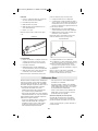
Influences on Accuracy
The ambient temperature has the greatest
influence. Especially temperature differences
occurring from the ground upward can divert
the laser beam.
As thermal fluctuation is largest close to the
ground, the tool, if possible, should be
mounted on a commercially available tripod
and placed in the center of the working area.
Apart from exterior influences, device-
specific influences (such as heavy impact or
falling down) can lead to deviations.
Therefore, check the accuracy of the tool
each time before starting your work.
Should the tool exceed the maximum
deviation during one of the tests, see
recalibration procedure or have it
recalibrated by a Bosch after-sales
service center.
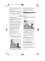
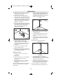
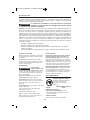
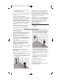
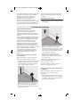
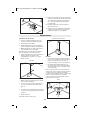
Checking the Horizontal Leveling
Accuracy of the Lateral Axis
A free measuring distance of 78 ft on a firm
surface in front of a wall is required for
the check.
– Mount the measuring tool onto the multi-
purpose attachment or a tripod, or place it
on a firm and level surface at a distance of
78 ft to the wall. Switch the tool on.
– Direct one of the two lateral laser beams,
that run alongside the lateral axis of the
tool, at the wall. Allow the tool to level in.
Mark the center of the laser beam on the
wall (point I).
– Rotate the measuring tool by approx. 180°
without changing its height. Allow it to level
in and mark the center point of the other
lateral laser beam on the wall (point II).
Take care that point II is as vertical as
possible above or below point I.
– The difference d of both marked points I
and II on the wall results in the actual
height deviation of the tool alongside the
lateral axis.
On the measuring distance of 2 x 78 ft = 156
ft, the maximum allowable deviation is:
156 ft x ±0.0036 in/ft = ±9/16 in (.563).
Thus, the difference d between points I and II
may not exceed 9/16 in (max.).
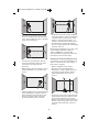
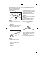
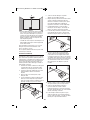
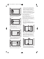
Checking the Horizontal Leveling
Accuracy of the Longitudinal Axis
A free measuring distance of approximately
78 ft on a firm surface between two walls A
and B is required for the check.
– Mount the tool onto the multi-purpose
attachment or a tripod, or place it on a firm
and level surface close to wall A. Switch
the tool on.
78 ft
d
180˚
possible, e.g. because the surface on which
the tool stands deviates by more than 5° (or
3° from the horizontal plane) the laser beams
flash rapidly.
In this case, bring the tool to the level
position and wait for the self-leveling to take
place. As soon as the tool is within the self-
leveling range of ±5° or ±3° respectively, all
laser beams light up continuously again.
In case of ground vibrations or position
changes during operation, the tool is
automatically levelled in again. To avoid
errors by moving the tool, check the position
of the laser beams with regard to the
reference points upon re-leveling.
Working Advice
• Always use the center of the laser point
for marking. The size of the laser point
changes with the distance
Leveling Accuracy
GPL5 manual-3_REV3:Bosch 10/26/11 6:48 PM Page 7

-8-
– Direct the horizontal laser beam against
the close wall A and allow the measuring
tool to level in. Mark the center of the laser
beam on the wall (point I).
– Turn the tool around by 180°, allow it to
level in and mark the center point of the
laser beam on the opposite wall
B (point II).
– Without turning the tool, position it close to
wall B. Switch the tool on and allow it to
level in.
– Align the height of the tool (using the tripod
or by underlaying, if required) in such a
manner that the center point of the laser
beam is projected exactly against the
previously marked point II on wall B.
– Rotate the tool by 180° without changing
the height. Allow it to level in and mark the
center point of the laser beam on wall A
(point III). Take care that point III is as
vertical as possible above or below point I.
– The difference d of both marked points I
and III on wall A indicates the actual height
deviation of the tool.
On the measuring distance of 2 x 78 ft = 156
ft, the maximum allowable deviation is:
156 ft x ±0.0036 in/ft = ±9/16 in(.563).
Thus, the difference d between points I and
III should not exceed 9/16 in (max.).
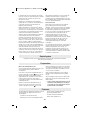
Checking the Vertical Leveling Accuracy
For this check, a free measuring distance of
approx. 13 ft between floor and ceiling on a
firm surface is required.
– Draw a straight line on the ceiling.
– Mount the tool to the multi-purpose
attachment or a tripod. Switch the tool on
and rotate it in such a manner that the
bottom plumb beam can be seen on
the floor.
– Position the tool in such a manner that the
upper plumb beam points against the line
on the ceiling. Allow the tool to level in.
Mark the center of the upper laser point on
the line on the ceiling (point I). Also, mark
the center of the laser point on the floor
(point II).
A
B
d
180˚
A
B
13 ft
A
B
78 ft
A
B
180˚
GPL5 manual-3_REV3:Bosch 10/26/11 6:48 PM Page 8

-9-
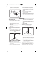
– Rotate the tool by 180°. Position it in such
a manner that the center of the bottom
laser point is directed on the already
marked point II and the upper laser point is
directed against the line on the ceiling.
Allow the tool to level in. Mark the center
of the upper laser point on the line on the
ceiling (point III).
– The difference d of both marked points I
and III on the ceiling results in the actual
deviation of the tool to the plumb line.
On the measuring distance of 2 x 13 ft = 26 ft
, the maximum allowable deviation is:
26 ft x ±0.0036 in/ft = ±3/16 in.
Thus, the difference d between points I and
III should not exceed 3/16 in (max.).
Recalibration Procedure
All tools are calibrated when processed
through the Bosch quality control program.
This process assures that the customer
receives a superior product which conforms
to the Product Specifications. Although tools
have been calibrated before reaching our
customers, it contains many precision
machined parts which may be affected if the
instrument is subjected to abuse. Therefore,
if the device is ever dropped or sustains
significant impact, the user should check
calibration by following these steps:
1. Select a site to be used as a calibration
range that will allow the tool to be placed
between two smooth vertical surfaces
directly opposite each other at a 100'
distance. (50' minimum)
2. Locate the two calibration ports on the
front and side of tool with a flathead
screwdriver.
3. Set tool on a level surface at one end of
the range.
4. When calibrating, position the side laser
beam (on the calibration port side) on the
vertical surface at the opposite end of the
range and mark this point on the surface.
5. Rotate tool around 180 degrees, taking
care not to change the height of
the device.
6. Position the other side laser beam on the
same vertical surface and mark this point
on the surface.
7. If this second mark is positioned at the
same height as the mark made in step 4,
proceed to step 13, otherwise, proceed to
the next step.
8. The goal of the next few steps is to
position both side beams at a height
halfway between the marks made in step
4 and in step 6.
9. Insert the screwdriver into the side
calibration port. Locate the calibration
screw and rotate it in a clockwise
direction to lower the beam or in the
counter clockwise direction to raise
the beam. Ensure that the beam is at a
height exactly halfway between the
marks made in Steps 4 and 6. Mark this
point on the surface.
4
6
5
50-100 feet
9
1
1/2
10
d
GPL5 manual-3_REV3:Bosch 10/26/11 6:48 PM Page 9

-10-
10. Repeat Steps 5 through 9 to confirm the
calibration of the side beams and
proceed to the next step.
11. Rotate the tool around 90 degrees
and position the front laser beam on the
vertical surface. Compare the height of
this beam with the height of the calibrated
side beams. If the height of this beam
matches the height of the side beams,
calibration is complete.
12. The goal of the next step is to position
the front beam at the same height as the
last mark to be made in the previous
steps or at the same height as the
calibrated side beams.
13. Insert screwdriver into the front
calibration port. Locate the calibration
screw and rotate it in a clockwise
direction to the raise the beam or in the
counter-clockwise direction to lower
the beam.
14. Turn the tool and check the height
of the front beam again.
15. Repeat steps 12 steps through 14 until
the front beam matches the height of the
two calibrated side beams.
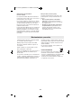
Plumbing a surface
1. Position tool close to the surface to
be plumbed.
2. Turn on tool.
3. Measure distance A at a point relatively
close to tool and make a note of
the distance.
4. Measure distance B at a point further
away from tool and make a note of
the distance.
Note: The greater the distance between the
two points of measurement, the greater
the accuracy.
5. Compare distance A with distance B. If
distance A equals distance B, then the
surface is plumb. If distance A does not
equal distance B, then the surface is not
plumb and should be corrected.
Plumb
Transferring points with the plumb beam
1. Mark the point to be transferred (labeled
A in this illustration).
2. Use the Mounting accessory or a Tripod
to position the plumb down beam over
point A.
3. The plumb up beam will transfer this point
along a perfectly vertical axis to point B.
4. Mark point B.
Note: This process may be reversed.
Plumb Transfer
Leveling
1. Adjust the height of tool using the
mounting accessory or a tripod so that
the horizontal beam hits a reference point
(labeled A in this illustration).
2. Rotate tool around its mounting axis to
position the front level beam at a point of
interest (labeled B in this illustration).
Note: It is possible to use the beam as a
leveling instrument without marking a line
Applications
A
B
11
14
A
B
GPL5 manual-3_REV3:Bosch 10/26/11 6:48 PM Page 10

-11-
through beam locations, however, some may
find it more satisfying to mark the beam
location at a variety of points and then create
a straight line through those points to
achieve a level line.
Level
Grading
1. Position tool at the highest point of
the surface to be graded.
2. Turn tool on.
3. Measure distance A and make a note of
the distance.
4. Measure distance B at distance X away
from A and note these distances.
5. Slope = (B – A)/X
Note: To calculate Pitch, set X equal to 12”.
Grade
Squaring
1. Position tool in the corner of the
two surfaces to be squared (as illustrated).
2. Turn tool on.
3. Measure distance A at a point relatively
close to tool and make a note of
the distance.
4. Measure distance B at a point further
away from tool and make a note of
the distance.
Note: The greater the distance between the
two points of measurement, the greater
the accuracy.
5. Compare distance A with distance B.
6. If distance A equals distance B, proceed to
the next step. If distance A does not equal
distance B, then adjust the position of
tool until distance A does equal
distance B and proceed to the next step.
7. Measure distance Y at a point relatively
close to tool and make a note of
the distance.
8. Measure distance Z at a point further away
from tool and make a note of
the distance.
Note: The greater the distance between the
two points of measurement, the greater
the accuracy.
9. Compare distance Y with distance Z
Square
10. If distance Y equals distance Z, then
the two surfaces are square. If distance Y
does not equal distance Z, then adjust the
position of the surface which these
distances relate to until distance Y does
equal distance Z.
Note: The plumb beams can also be used in
operations such as squaring window frames.
B
Y
A
Z
A
B
B
A
x
GPL5 manual-3_REV3:Bosch 10/26/11 6:48 PM Page 11

-12-
To fasten the tool on the Multiple-Purpose
Attachment 8, screw the locking screw 9 of
the Multiple-Purpose Attachment into the
1/4" tripod mount 6 on the tool and tighten.
To rotate the tool on the Multiple-Purpose
Attachment, slightly loosen the screw 9.
– Rotate the tool on the Multiple-Purpose
Attachment 8 sideward or toward the rear
to make the bottom plumb beam visible.
– Rotate the tool on the Multiple-Purpose
Attachment 8 to project heights with the
horizontal laser beam.
With the Multiple-Purpose Attachment 8, the
tool can be attached as follows:
– Mount the Multiple-Purpose Attachment 8
to a commercially available camera tripod
via the 1/4" tripod mount 13. For fastening
to a commercially available construction
tripod, use the 5/8" tripod mount 14.
– The Multiple-Purpose Attachment 8 can be
fastened to steel parts via the magnets 12.
– The Multiple-Purpose Attachment 8 can be
fastened to drywall or wood walls with
screws. For this, insert screws with a
minimum length of 2 in. into the screw
holes 10 of the Multiple-Purpose
Attachment.
– The Multiple-Purpose Attachment 8 can
also be fastened to pipes or similar beams
using a commercially available strap by
threading it through the opening 11 for
strap attachment.
Working with the Tripod (Optional
Accessory)
A tripod 18 offers a stable, height-adjustable
measuring support. Place the tool via the
tripod mount 6 onto the 1/4-20 and 5/8-11
male thread of the tripod and screw the
locking screw of the tripod tight.
Working with the Measuring Plate
(Optional Accessory)
With the measuring plate 15, it is possible to
project the laser mark onto the floor or the
laser height onto a wall.
With the zero field and the scale, the offset or
drop to the required height can be measured
and projected at another location. This
eliminates the necessity of precisely adjusting
the tool to the height to be projected.
The measuring plate 15 has a reflective
coating that enhances the visibility of the
laser beam at greater distances or in intense
sunlight. The brightness intensification can
be seen only when viewing, parallel to the
laser beam, onto the measuring plate.
Laser Viewing Glasses
(Optional Accessory)
The laser viewing glasses filter out the
ambient light. This makes the red light of the
laser appear brighter for the eyes.
• Do not use the laser viewing glasses as
safety goggles. The laser viewing glasses
are used for improved visualization of the
laser beam, but they do not protect against
laser radiation.
• Do not use the laser viewing glasses as
sun glasses or in traffic. The laser
viewing glasses do not afford complete UV
protection and reduce color perception.
Use with Attachments
GPL5 manual-3_REV3:Bosch 10/26/11 6:48 PM Page 12

-13-
LIMITED WARRANTY OF BOSCH LASER AND
MEASURING TOOL PRODUCTS
Limited Warranty Program
Robert Bosch Tool Corporation ("Seller") warrants to the original purchaser only, that all Bosch lasers and measuring tools will be free from
defects in material or work¬manship for a period of one (1) year from date of purchase. Bosch will extend warranty coverage to two (2)
years when you register your product within eight (8) weeks after date of purchase. Product registration card must be complete and mailed
to Bosch (postmarked within eight weeks after date of purchase), or you may register on-line at
www.boschtools.com/Service/ProductRegistration
. If you choose not to register your product, a one (1) year limited warranty will apply to
your product.
30 Day Money Back Refund or Replacement -
If you are not completely satisfied with the performance of your laser and measuring tools, for any reason, you can return it to your Bosch
dealer within 30 days of the date of purchase for a full refund or replacement. To obtain this 30-Day Refund or Replacement, your return
must be accompanied by the original receipt for purchase of the laser or optical instrument product. A maximum of 2 returns per customer
will be permitted.
SELLER'S SOLE OBLIGATION AND YOUR EXCLUSIVE REMEDY under this Limited Warranty and, to the extent permitted by law, any
warranty or condition implied by law, shall be the repair or replacement of parts, without charge, which are defective in material or
workmanship and which have not been misused, carelessly handled, or misrepaired by persons other than Seller or Authorized Service
Center. To make a claim under this Limited Warranty, you must return the complete Bosch laser or measuring tool, transportation prepaid,
to any BOSCH Factory Service Center or Authorized Service Center. Please include a dated proof of purchase with your tool. For locations
of nearby service centers, please use our on-line service locator or call 1-877-267-2499.
THIS WARRANTY PROGRAM DOES NOT APPLY TO TRIPODS AND RODS. Robert Bosch Tool Corporation ("Seller") warrants tripods
and leveling rods for a period of one (1) year from date of purchase.
THIS LIMITED WARRANTY DOES NOT APPLY TO OTHER ACCESSORY ITEMS AND RELATED ITEMS. THESE ITEMS RECEIVE A 90
DAY LIMITED WARRANTY.
To make a claim under this Limited Warranty, you must return the complete product, transportation prepaid. For details to make a claim
under this Limited Warranty please visit www.boschtools.com or call 1-877-267-2499.
ANY IMPLIED WARRANTIES SHALL BE LIMITED IN DURATION TO ONE YEAR FROM DATE OF PURCHASE. SOME STATES IN THE
U.S., AND SOME CANADIAN PROVINCES DO NOT ALLOW LIMITATIONS ON HOW LONG AN IMPLIED WARRANTY LASTS, SO THE
ABOVE LIMITATION MAY NOT APPLY TO YOU.
IN NO EVENT SHALL SELLER BE LIABLE FOR ANY INCIDENTAL OR CONSEQUENTIAL DAMAGES (INCLUDING BUT NOT LIMITED
TO LIABILITY FOR LOSS OF PROFITS) ARISING FROM THE SALE OR USE OF THIS PRODUCT. SOME STATES IN THE U.S., AND
SOME CANADIAN PROVINCES DO NOT ALLOW THE EXCLUSION OR LIMITATION OF INCIDENTAL OR CONSEQUENTIAL
DAMAGES, SO THE ABOVE LIMITATION MAY NOT APPLY TO YOU.
THIS LIMITED WARRANTY GIVES YOU SPECIFIC LEGAL RIGHTS, AND YOU MAY ALSO HAVE OTHER RIGHTS WHICH VARY FROM
STATE TO STATE IN THE U.S., OR PROVINCE TO PROVINCE IN CANADA AND FROM COUNTRY TO COUNTRY.
THIS LIMITED WARRANTY APPLIES ONLY TO PRODUCTS SOLD WITHIN THE UNITED STATES OF AMERICA, CANADA AND THE
COMMONWEALTH OF PUERTO RICO. FOR WARRANTY COVERAGE WITHIN OTHER COUNTRIES, CONTACT YOUR LOCAL
BOSCH DEALER OR IMPORTER.
Store and transport the tool only in the
supplied protective case.
Keep the tool clean at all times.
Do not immerse the tool into water or
other fluids.
Wipe off debris using a moist and soft cloth.
Do not use any cleaning agents or solvents.
Regularly clean the surfaces at the exit
opening of the laser in particular, and pay
attention to any fluff of fibers.
If the tool should fail despite the care taken in
manufacturing and testing procedures, repair
should be carried out by an authorized after-
sales service center for Bosch power tools.
In all correspondence and spare parts
orders, please always include the 10-digit
article number given on the type plate of
the tool.
In case of repairs, send in the tool packed in
its protective case 16.
ENVIRONMENT PROTECTION
Recycle raw materials & batteries instead of
disposing of waste. The unit, accessories,
packaging & used batteries should be sorted
for environmentally friendly recycling in
accordance with the latest regulations.
Maintenance and Service
GPL5 manual-3_REV3:Bosch 10/26/11 6:48 PM Page 13

Lisez toutes les instructions. Le
non-respect de toutes les instructions figurant ci-dessous
risquerait de causer une exposition dangereuse aux
rayonnements, un choc électrique, un incendie et/ou des
blessures graves. L'expression « instrument de topologies »
dans tous les avertissements figurant plus bas fait référence
à votre instrument de mesure, de détection et de tracé de
topologies branché sur le secteur (avec cordon) ou à votre
instrument de mesure, de détection et de tracé de topologies
à piles (sans fil).
Les étiquettes suivantes sont
apposées sur votre instrument
laser pour votre commodité et votre sécurité. Elles indiquent où la lumière laser est émise par le instrument. IL
FAUT TOUJOURS CONNAÎTRE sa position lors de l'utilisation du instrument.
Utilisez l'outil correct pour votre application.
Ne dirigez pas le faisceau laser en direction de personnes ou d'animaux, et ne regardez pas
directement le faisceau laser vous-même. Cet instrument produit des rayonnements laser de
classe II et est conforme aux normes 21 CFR 1040.10 et 1040.11, à l'exception des déviations
en vertu de l'Avis relatif au laser N° 50 daté du 24 juin 2007. Ceci risquerait de causer
l'aveuglement des personnes affectées.
Tout changement ou modification apporté(e) à ce matériel n'ayant pas fait l'objet d'un accord préalable donné
par les personnes responsables en la matière pourrait annuler le droit de l'utilisateur d'utiliser le matériel.
L'utilisation des commandes, la réalisation de réglages ou l'exécution de procédures autres que ce qui est
indiqué aux présentes risquerait de causer une exposition dangereuse aux
rayonnements.
NE RETIREZ PAS et n'effacez pas des étiquettes d'avertissement ou de mise en garde. Le retrait de telles
étiquettes augmente le risque d'exposition aux rayonnements laser. L'emploi de commandes ou de réglages
autres que ceux qui sont indiqués dans ce mode d'emploi risquerait de causer une exposition dangereuse aux
rayonnements.
ASSUREZ-VOUS TOUJOURS que les personnes présentes aux environs de l'endroit où vous employez cet
instrument sont au courant des dangers résultant de l'observation directe du faisceau laser.
NE PLACEZ PAS l'instrument dans une position telle que cela permettrait à quiconque de regarder directement
le faisceau laser intentionnellement ou non. Ceci risquerait de causer des blessures graves aux yeux.
POSITIONNEZ TOUJOURS l'instrument de façon qu'il soit stable. La chute de l'instrument risquerait
d'endommager ce dernier et/ou de causer des blessures graves à son utilisateur.
N'UTILISEZ TOUJOURS que les accessoires qui sont recommandés par le fabricant de votre instrument.
L'emploi d'accessoires qui ont été conçus pour emploi avec d'autres outils risquerait de causer des
blessures graves.
N'UTILISEZ PAS cet instrument dans un but autre que ceux qui sont indiqués dans ce mode d'emploi. Ceci
risquerait de causer des blessures graves.
NE LAISSEZ PAS l'instrument allumé (« ON ») sans surveillance dans un mode de fonctionnement quelconque.
NE DÉMONTEZ PAS l'instrument. Il ne contient aucune pièce pouvant être réparée par l'utilisateur. Ne modifiez
ce produit en aucune façon. Toute modification de cet instrument risquerait de causer une exposition
dangereuse aux rayonnements.
N'UTILISEZ PAS les verres de visionnement du laser à la place de lunettes de protection. Les verres de
visionnement du laser sont utilisés pour améliorer la visualisation du faisceau laser, mais ils ne protègent pas
contre les rayonnements laser.
N'UTILISEZ PAS pas les verres de visionnement du laser en guise de lunette de soleil ou lorsque vous
conduisez un véhicule. Ces verres n'assurent pas une protection complète contre les rayons UV et ils
réduisent la perception des couleurs.
N'UTILISEZ PAS d'instruments optiques tels, que, entre autres, des télescopes ou des lunettes d'astronome
pour regarder le faisceau laser. Ceci risquerait de causer des blessures graves aux yeux.
NE FIXEZ PAS directement des yeux le faisceau laser et ne projetez pas la faisceau laser directement dans les
yeux d'autres personnes. Ceci risquerait de causer des blessures graves aux yeux.
CONSERVEZ CES INSTRUCTIONS.
-14-
Consignes générales de sécurité
!
AVERTISSEMENT
!
AVERTISSEMENT
!
MISE EN GARDE
GPL5 manual-3_REV3:Bosch 10/26/11 6:48 PM Page 14

Sécurité sur le lieu de travail
Maintenez votre lieu de travail propre et bien éclairé.
Les lieux de travail encombrés ou sombres invitent
les accidents.
N'UTILISEZ PAS l'instrument laser à proximité
d'enfants, et ne laissez pas des enfants se servir de
l'instrument laser. Cela risquerait de produire des
blessures graves aux yeux.
Sécurité électrique
Les piles risquent
d'exploser ou de fuir, et de
causer des blessures ou un incendie. Afin de réduire
ce risque, suivez toujours toutes les instructions et
tous les avertissements figurant sur l'étiquette des
piles et sur l'emballage.
NE COURT-CIRCUITEZ PAS de bornes des piles.
NE RECHARGEZ PAS des piles alcalines.
NE MÉLANGEZ PAS des piles neuves et des piles
usagées. Remplacez toutes les piles en même temps
par des piles neuves de la même marque et du
même type.
NE MÉLANGEZ PAS des piles ayant des compositions
chimiques différentes.
Jetez ou recyclez les piles conformément aux
règlements du code local.
NE JETEZ PAS des piles dans un feu.
Gardez les piles hors de la portée des enfants.
Retirez les piles si vous ne pensez pas utiliser cet
instrument pendant plusieurs mois.
Sécurité personnelle
Restez alerte, surveillez ce que vous źtes en train de
faire et faites preuve de bons sens lorsque vous
utilisez un quelconque outil. N'utilisez pas un outil
pendant que vous êtes fatigué(e) ou sous l'influence
de drogues, d'alcool ou de médicaments. Un moment
d'inattention pendant que vous vous servez d'un outil
risquerait de causer de graves blessures personnelles
ou de produire des résultats de mesures imprécis.
Utilisez des équipements de sécurité. Portez toujours
une protection des yeux. Des équipements tels que
des masques antipoussières, des chaussures de
sécurité antidérapantes, un casque ou une protection
des oreilles utilisés pour les conditions appropriées
réduiront les blessures corporelles.
Fixation multifonctionelle
Ne pas mettre la fixation multifonctionelle 8 dans la
proximité de stimulateurs cardiaques.
Les disques magnétiques 12 génèrent
un champ qui peut entraver le
fonctionnement de stimulateurs
cardiaques.
• Maintenir la fixation éloignée des
support de données
magnétiques et des appareils
réagissant aux sources magnétiques.L'effet du
disque magnétique 12 peut entraîner des pertes de
données irréversibles.
Utilisation et entretien
Utilisez l'outil correct pour votre application.
!
AVERTISSEMENT
Déclaration de la FCC
Cet appareil est conforme a la partie 15 des Reglements de la FCC. Son utilisation est autorisee
moyennant le respect des deux conditions suivantes : (1) Cet appareil ne doit pas causer d’interferences
nuisibles et (2) cet appareil doit accepter toute interference recue, y compris les interferences qui
risquent de causer un fonctionnement indesirable.
Les changements ou modifications à cette unité n'étant pas expressément
approuvé par la partie responsable de la conformité pourrait annuler l'autorité
de l'utilisateur de faire fonctionner l'équipement.
Remarque : Cet equipement a ete teste et juge conforme aux limites pour un equipement numerique de
Classe B en vertu de la Partie 15 des Reglements de la FCC. Ces limites sont concues pour assurer une
protection raisonnable contre les interferences nuisibles dans une installation residentielle. Cet
equipement emet, utilise et peut rayonner de l’energie de frequence radio et, s’il n’est pas installe et
utilise conformement aux instructions, il pourrait causer des interferences nuisibles aux communications
radio. Cependant, il n’existe aucune garantie qu’aucune interference ne se produira dans une installation
particuliere. Si cet equipement cause des interferences nuisibles pour la reception de programmes a la
radio ou a la television, ce qui peut etre determine en allumant et en eteignant a plusieurs reprises
l’equipement en question, l’utilisateur est encourage a corriger l’interference en prenant une ou plusieurs
des mesures suivantes :
- Reorienter ou deplacer l’antenne de reception.
- Augmenter la distance entre l’equipement et le recepteur.
- Connecter l’equipement a une prise de courant raccordee a un circuit different de celui auquel le
recepteur est connecte.
- Consulter le detaillant ou un technicien radio ou television experimente pour lui demander conseil.
!
AVERTISSEMENT
-15-
GPL5 manual-3_REV3:Bosch 10/26/11 6:48 PM Page 15

Mise en place/changement des piles
Pour le fonctionnement de l’appareil de mesure, nous
recommandons d’utiliser des piles alcalines
au manganèse.
Pour ouvrir le couvercle du compartiment à piles 3,
tournez le blocage 2 en position dans le sens des
aiguilles d’une montre et retirez le couvercle du
compartiment à piles. Introduisez les piles fournies.
Veillez à la bonne position des pôles qui doit
correspondre à la figure se trouvant à l’intérieur du
compartiment à piles.
Montez le couvercle du compartiment à piles en
dessous sur le boîtier et poussez-le vers le haut.
Tournez le blocage 2 en position dans le sens
inverse des aiguilles d’une montre pour verrouiller le
couvercle du compartiment à piles. Si les faisceaux
laser clignotent à un rythme lent pendant le service,
c’est que les piles sont faibles.
Après le premier clignotement, il est possible de
continuer à utiliser l’appareil de mesure pendant
8 h env.
Toujours remplacer toutes les piles en même temps.
N’utiliser que des piles de la même marque avec la
même capacité.
• Sortir les piles de l’appareil de mesure au cas oĚ
l’appareil ne serait pas utilisé pour une période
assez longue. En cas de stockage long, les piles
peuvent corroder et se décharger.
L’appareil de mesure est conçu pour déterminer et vérifier des lignes horizontales et verticales
ainsi que des points d’aplomb.
-16-
Préparation
Emploi prévu
L'instrument de mesure, de détection et de tracé de
topologies correct vous permettra de faire un meilleur
travail et avec plus de sécurité à la vitesse pour
laquelle il a été conçu.
N'utilisez pas cet instrument si l'interrupteur ne
s'allume pas ou ne s'éteint pas. Un instrument qui ne
peut pas être contrôlé par son interrupteur est
dangereux et doit être réparé.
Rangez l'instrument hors de la portée des enfants
lorsque vous ne vous en servez pas, et ne laissez pas
de personnes ne connaissant pas bien cet instrument
ou n'ayant pas lu ce mode d'emploi mettre l'outil en
marche. De tels instruments pourraient être
dangereux entre les mains d'utilisateurs n'ayant pas
reçu la formation nécessaire à leur utilisation.
Entretenez vos instruments. Assurez-vous que les
pièces sont alignées correctement et que les pièces
mobiles ne se coincent pas, qu'il n'y a pas de pièces
brisées ou d'autres conditions pouvant affecter le
fonctionnement. Réparez tout instrument endommagé
avant de vous en servir. Tout outil endommagé doit
être réparé par le centre de service après-vente agréé
de Bosch avant d’être employé à nouveau. De
nombreux accidents par des instruments de mesure,
de détection et de tracé de topologies mal entretenus.
Utilisez l'outil, les accessoires, etc. conformément à
ce mode d'emploi et de la manière prévue pour le
type particulier d'instrument, en tenant compte des
conditions de travail à réaliser. L'emploi de cet
instrument pour des opérations différentes de celles
qui sont indiqués dans le mode d'emploi risquerait de
causer une situation dangereuse.
Service aprŹs-vente
Faites réparer votre instrument par un réparateur
agréé n'utilisant que des pièces de rechange
identiques. Ceci assurera le respect des prescriptions
de sécurité pour l'instrument. Préparez un calendrier
de maintenance périodique pour l'instrument.
Lorsque vous nettoyez un instrument, faites attention
de ne pas démonter une partie quelconque de
l'instrument étant donné que des fils internes
risqueraient d'être déplacés ou pincés, ou qu'ils
pourraient être remontés de façon incorrecte. Certains
produits de nettoyage tels que de l'essence, du
tétrachlorure de carbone, de l'ammoniac, etc.
risqueraient d'endommager les composants
en plastique.
Il n'est possible de travailler en toute sécurité avec cet
instrument qu'après avoir lu toutes les informations
relatives à son utilisation et à la sécurité, et à
condition de respecter rigoureusement toutes les
instructions contenues dans le mode d'emploi. Ne
rendez jamais illisibles les étiquettes d'avertissement
se trouvant sur l'instrument.
La numérotation des éléments de l’appareil se réfère à
la représentation de l’appareil de mesure sur la
page graphique.
1 Orifice de sortie du faisceau laser
2 Blocage du couvercle du compartiment à piles
3 Couvercle du compartiment à piles
4 Interrupteur Marche/Arrêt
5 Plaque d’avertissement de laser
6 Raccord de trépied 5/8-11"
Features
GPL5 manual-3_REV3:Bosch 10/26/11 6:48 PM Page 16

-17-
Mise en service
• Protéger l’appareil de mesure contre l’humidité,
ne pas l’exposer aux rayons directs du soleil.
• Ne pas exposer l’appareil de mesure ą des
températures extrźmes ou de forts changements de
température. Ne le laissez pas traîner longtemps
dans la voiture par ex. En cas d’importants
changements de température, laissez l’appareil de
mesure prendre la température ambiante avant de le
mettre en service. Des températures extrêmes ou de
forts changement de température peuvent entraver
la précision de l’appareil de mesure.
• Eviter les chocs ou les chutes de l’appareil de
mesure. Lorsque l’appareil de mesure a été soumis à
de fortes influences extérieures, toujours effectuer
un contrôle de précision avant de continuer à
travailler (voir « Précision de nivellement »).
N’utilisez pas l’outil quand le cache du point
d’émission du laser a été endommagé à la suite d’un
choc important ayant affecté l’extérieur de l’outil. De
nombreux accidents par des instruments de
mesure, de détection et de tracé de topologies mal
entretenus.
• Eteignez l’appareil de mesure quand vous le
transportez. Lorsque l’appareil est éteint, l’unité
pendulaire se verrouille afin de prévenir son
endommagement lors de mouvements forts.
Mise en Marche/Arrźt
Pour mettre en marche l’appareil de mesure, poussez
l’interrupteur Marche/Arrêt 4 avant de sorte que « I »
apparaisse sur l’interrupteur. Immédiatement après
avoir été mis en marche, l’appareil de mesure envoie
un faisceau laser à travers chaque orifice de sortie 1.
• Ne pas diriger le faisceau laser vers des personnes
ou des animaux et ne jamais regarder ans le
faisceau laser, même si vous êtes à grande distance
de ce dernier.
Pour éteindre l’appareil de mesure, poussez
l’interrupteur Marche/Arrêt 4 arrière de sorte que « 0 »
apparaisse sur l’interrupteur. Lorsque l’appareil est
éteint, l’unité pendulaire est verrouillée.
Réglage de la coupure automatique
L’appareil de mesure se met automatiquement hors
fonctionnement 20 min après sa mise en service.
Il est possible de modifier cette coupure automatique
de 20 min à 8 h. Pour ce faire, mettez l’appareil de
mesure en fonctionnement, éteignez-le immédiatement
et remettez-le en marche en l’espace de 4 s. Pour
confirmer la modification, tous les faisceaux laser
clignotent à un rythme rapide pendant 2 s après la
deuxième mise en marche.
• Ne pas laisser sans surveillance l’appareil de
mesure allumé et éteindre l’appareil de mesure
Consignes d’utilisation
Zone de travail
– Standard . . . . . . . . . . . . . . . . . . . . . . . . . . . . . . .30 m
Précision de nivellement . . . . . . . . . . . . . . ±0,3 mm/m
Plage typique de nivellement
automatique le long de
– l’axe longitudinal . . . . . . . . . . . . . . . . . . . .jusqu’á ±5°
– l’axe transversal . . . . . . . . . . . . . . . . . . . . . . . . . . ±3°
Température de service . . . . . . . . . . . . . . .–10°C+40 °C
Température de stockage . . . . . . . . . . . .–20°C+70 °C
Humidité relative de l’air max. . . . . . . . . . . . . . . .90 %
Classe laser . . . . . . . . . . . . . . . . . . . . . . . . . . . . . . . . 2
Type de laser . . . . . . . . . . . . . . . . . 635nm, <1 mW
Raccord de trépied . . . . . . . . . . . . . . . . . . . . . .5/8-11
Piles . . . . . . . . . . . . . . . . . . . . . . . 4 x 1,5 V LR6 (AA)
Durée de service env . . . . . . . . . . . . . . . . . . . . . . . .24 h
Poids suivant EPTA-Procédure 01/2003 . . . . . .725 g
Dimensions . . . . . . . . . . . . . . . . . . 105 x 80 x 42 mm
Faire attention au numéro d’article se trouvant sur la
plaque signalétique de l’appareil de mesure. Les
désignations commerciales des différents appareils
peuvent varier.
Pour permettre une identification précise de votre
appareil de mesure, le numéro de série 7 est marqué
sur la plaque signalétique.
Données techniques
7 Numéro de série
8 Fixation multifonctionelle
9 Vis de serrage de la fixation multifonctionelle
10 Trous filetés de la Fixation multifonctionelle
11 Guidage de la bande
12 Aimants
13 Raccord de trépied 1/4-20 de la fixation
14 Raccord de trépied 5/8-11 de la fixation
15 Platine de mesure avec pied*
16 Etui de protection
17 Lunettes de vision du faisceau laser
18 Trépied*
*Les accessoires décrits ou montrés ne sont pas
compris dans l’emballage standard.
GPL5 manual-3_REV3:Bosch 10/26/11 6:48 PM Page 17

-18-
Influences sur la précision
C’est la température ambiante qui exerce la plus grande
influence. Ce sont notamment les différences de
température entre le sol et la hauteur de travail qui
peuvent faire dévier le faisceau laser.
Puisque la stratification de la température est à son
maximum à proximité du sol, l’appareil de mesure
devrait toujours être monté sur un trépied disponible
dans le commerce, si possible, et être installé au centre
le la zone de travail.
Outre les influences extérieures, des influences
spécifiques à l’appareil (par ex. chutes ou chocs
violents) peuvent entraîner de légères divergences.
Avant de commencer tout travail, contrôler donc la
précision de l’appareil de mesure.
Si l’appareil de mesure dépasse la divergence maximale
de précision pour un des contrôles, le faire réparer par
un service après-vente Bosch.
Contrôler la précision de nivellement horizontal
de l’axe transversal
Pour ce contrôle, on nécessite une distance dégagée de
20 m sur un sol stable devant un mur.
– Montez l’appareil de mesure à une distance de 20 m
du mur sur la fixation ou un trépied ou placez-le sur
un sol solide et plan. Mettez l’appareil de mesure
en fonctionnement.
– Dirigez un des deux faisceaux laser latéraux qui
courent le long de l’axe transversal de l’appareil de
mesure, en direction du mur. Laissez l’appareil de
mesure effectuer un nivellement automatique.
Marquez le milieu du point laser sur le mur (point I).
– Tournez l’appareil de mesure de 180° env. sans
modifier la hauteur. Laissez-le effectuer un
nivellement automatique et marquez le milieu du
point de l’autre faisceau laser latéral sur le mur
(point II). Veillez à ce que point II soit positionné
aussi vertical que possible au-dessus ou en-dessous
de point I.
– L’écart d entre les deux points I et II marqués sur le
mur indique la divergence de précision réelle de
l’appareil de mesure pour la hauteur le long de
l’axe transversal.
Pour une distance à mesurer de
2 x 20 m = 40 m, la divergence de précision
max. admissible est de de ± 4 mm.
40 m x ±0,3 mm/m = ±12 mm.
Par conséquent, la différence d entre les points I et II
ne doit être que 12 mm max.
20 m
aprŹs l’utilisation. D’autres personnes pourraient
être éblouies par le faisceau laser.
Lors de la prochaine mise en marche de l’appareil de
mesure, la coupure automatique est ànouveau réglée
sur 20 min.
Travailler avec nivellement automatique
Placez l’appareil de mesure sur un support horizontale
solide, montez-le sur la fixation 8 ou sur le trépied 18.
Une fois l’appareil mis en marche, le nivellement
automatique compense automatiquement les inégalités
à l’intérieur de la plage de nivellement automatique de
±5° (axe longitudinal) ou ±3° (axe transversal). Dès que
les points laser ne bougent plus, le nivellement
est terminé.
Si un nivellement automatique n’est pas possible, par
ex. parce que la surface où est posé l’appareil de
mesure diffère de plus de 5° ou de plus de 3° de
l’horizontale, les faisceaux laser clignotent au rythme
rapide. Dans un tel cas, placez l’appareil de mesure
horizontalement et attendez le nivellement automatique.
Dès que l’appareil de mesure se trouve à l’intérieur de
la plage de nivellement automatique de ±5° ou ±3°, les
faisceau laser restent à nouveau allumés
en permanence.
Dans le cas de secousses ou de modifications pendant
l’utilisation, l’appareil de mesure est automatiquement
nivelé à nouveau. Après le nivellement, vérifiez la
position des faisceaux laser par rapport aux points de
référence afin d’éviter des erreurs causées par un
déplacement de l’appareil de mesure.
Instructions d’utilisation
• Pour marquer, n’utiliser toujours que le milieu de
la ligne laser. La largeur de la ligne laser change
avec la distance.
Précision de nivellement
d
180˚
GPL5 manual-3_REV3:Bosch 10/26/11 6:48 PM Page 18

-19-
Contrôler la précision de nivellement horizontal
de l’axe longitudinal
Pour ce contrôle, on nécessite une distance dégagée de
20 m sur un sol stable entre deux murs A et B.
– Montez l’appareil de mesure près du mur A sur une
fixation ou un trépied ou placez-le sur un sol solide
et plan. Mettez l’appareil de mesure en
fonctionnement.
– Dirigez le faisceau laser horizontal sur le mur proche
A et laissez l’appareil de mesure effectuer le
nivellement automatique. Marquez le milieu du point
laser sur le mur (point I).
– Tourner l’appareil de mesure de 180°, le laisser
effectuer un nivellement automatique et marquer le
milieu du point du faisceau laser sur le mur en face
B (point II).
– Placer l’appareil de mesure – sans le tourner près du
mur B, le mettre en fonctionnement et le laisser
effectuer le nivellement automatique.
– Ajuster l’appareil de mesure en hauteur (à l’aide du
trépied ou, le cas échéant, par des cales
appropriées) de sorte que le milieu du point du
faisceau laser touche le point II sur le mur B
tracé auparavant.
– Tournez l’appareil de mesure de 180° sans modifier
la hauteur. Laissez-le effectuer un nivellement
automatique et marquez le milieu du point du
faisceau laser sur le mur A (point III). Veillez à ce
que point III soit positionné aussi verticalement que
possible au-dessus ou en-dessous du point I.
– L’écart d entre les deux points I et III marqués sur
mur A indique la divergence de précision réelle de
l’appareil de mesure pour la hauteur.
Pour une distance à mesurer de
2 x 20 m = 40 m, la divergence de précision
max. admissible est de :
40 m x ±0,3 mm/m = ±12 mm.
Par conséquent, la différence d entre les points I et III
ne doit être que 12 mm max.
Contrôler la précision du nivellement vertical
Pour ce contrôle, on nécessite une distance dégagée de
5 m sur un sol stable entre le sol et le plafond.
– Dessinez une ligne droite sur le plafond.
– Montez l’appareil de mesure sur la fixation ou un
trépied. Mettez l’appareil de mesure en
fonctionnement et tournez-le de sorte que le
faisceau d’aplomb inférieur soit visible sur le sol.
– Positionnez l’appareil de mesure de sorte que le
faisceau d’aplomb supérieur atteigne la ligne sur le
plafond. Laissez l’appareil de mesure effectuer un
nivellement automatique. Marquez le milieu du point
laser supérieur sur la ligne du plafond (point I).
Marquez également le milieu du point laser inférieur
sur le sol (point II).
5 m
d
180˚
A
B
A
B
20 m
A
B
180˚
A
B
GPL5 manual-3_REV3:Bosch 10/26/11 6:48 PM Page 19

-20-
– Tournez l’appareil de mesure de 180°. Positionnez-
le de sorte que le milieu du point laser inférieur se
trouve sur le point II déjà marqué et le point laser
supérieur sur la ligne du plafond. Laissez l’appareil
de mesure effectuer un nivellement automatique.
Marquez le milieu du point laser supérieur sur la
ligne du plafond (point III).
– L’écart d entre les deux points I et III marqués sur le
plafond indique la divergence réelle de l’appareil de
mesure de la verticale.
Pour une distance à mesurer de 2 x 5 m = 10 m, la
divergence de précision max. admissible est de :
10 m x ±0,3 mm/m = ±3 mm.
Par conséquent, la différence d entre les points I et III
ne doit être que 3 mm max.
Procédure de réétalonnage
Le outil est étalonné par Bosch dans le cadre de son
programme de contróle qualité. Ce processus garantit
que le client reèoit un produit de qualité supérieure, en
conformité avec les spécifications de produit assure. Si
l'instrument subit une chute ou un choc important ou
encore comme procédure d'entretien normale, son
étalonnage doit Ítre vérifié l'étalonnage en suivant les
étapes décrites ci-dessous
1. Sélectionnez un endroit oú étalonner le outil et placez
le à une distance entre 15 et 30 m d'une surface
verticale lisse, par exemple une paroi ou un mur.
2. Localisez les deux ports d’étalonnage sur les côtés
avant et latéral de l’outil avec un tournevis à
tête plate.
3. Placez le outil sur une surface plane, tel que
décrit plus haut.
4. Lors de l’étalonnage, positionnez le faisceau laser
latéral (sur le côté comprenant le port d’étalon-
nage) sur la surface verticale à l’extrémité opposée
du champ et marquez ce point sur la surface.
5. Tournez le outil de 180 degrés en prenant
garde de ne pas modifier sa hauteur.
6. Dirigez l'autre rayon latéral contre la mÍme surface
verticale et marquez l'emplacement du point
lumineux sur la surface. S'assurer que les rayons
laser clignotent rapidement confirmant que
l'appareil est au niveau et en mode d'étalonnage.
7. Si la deuxième marque se trouve à la mÍme
hauteur que celle de l'étape 4, allez à l'étape 13.
Dans le cas contraire, suivez l'étape suivante.
8. Le but des étapes suivantes est de placer les deux
rayons latéraux de sorte qu'ils se trouvent à mi-
hauteur des marques obtenues aux étapes 4 et 6.
9. Insérez le tournevis dans le port d’étalonnage
latéral. Localisez la vis d’étalonnage et faites-la
tourner dans le sens des aiguilles d’une montre
pour abaisser le faisceau ou dans le sens contraire
des aiguilles d’une montre pour élever le faisceau.
Assurez-vous que le faisceau est à une hauteur qui
est exactement à mi-chemin entre les marques
faites aux étapes 4 et 6. Marquez ce point sur
la surface.
10. Répéter les étapes 5 à 9 pour confirmer l'étalonnage
des rayons latéraux et passer à l'étape suivante.
11. Tournez le outil de 90 degrés et dirigez le
rayon laser avant sur la surface verticale.
Comparez la hauteur de ce rayon avec la hauteur
des rayons latéraux étalonnés. S'ils sont à la mÍme
hauteur, l'étalonnage est terminé.
12. Le but de l'étape suivante et de placer le rayon
avant à la hauteur que vous auriez du obtenir au
cours de l'étape précédente, c'est-à-dire à la mÍme
hauteur que les rayons latéraux étalonnés.
9
1
1/2
10
d
4
6
5
50-100 feet
GPL5 manual-3_REV3:Bosch 10/26/11 6:48 PM Page 20
La page est en cours de chargement...
La page est en cours de chargement...
La page est en cours de chargement...
La page est en cours de chargement...
La page est en cours de chargement...
La page est en cours de chargement...
La page est en cours de chargement...
La page est en cours de chargement...
La page est en cours de chargement...
La page est en cours de chargement...
La page est en cours de chargement...
La page est en cours de chargement...
La page est en cours de chargement...
La page est en cours de chargement...
La page est en cours de chargement...
La page est en cours de chargement...
-
 1
1
-
 2
2
-
 3
3
-
 4
4
-
 5
5
-
 6
6
-
 7
7
-
 8
8
-
 9
9
-
 10
10
-
 11
11
-
 12
12
-
 13
13
-
 14
14
-
 15
15
-
 16
16
-
 17
17
-
 18
18
-
 19
19
-
 20
20
-
 21
21
-
 22
22
-
 23
23
-
 24
24
-
 25
25
-
 26
26
-
 27
27
-
 28
28
-
 29
29
-
 30
30
-
 31
31
-
 32
32
-
 33
33
-
 34
34
-
 35
35
-
 36
36


Bosch GPL 2 Mode d'emploi
- Catégorie
- Niveaux laser
- Taper
- Mode d'emploi
dans d''autres langues
- English: Bosch GPL 2 Operating instructions
- español: Bosch GPL 2 Instrucciones de operación
Documents connexes
-
Bosch Power Tools GPL3 Manuel utilisateur
-
-
Bosch Power Tools GPL5 Manuel utilisateur
-
Bosch GTL2 GLL2 Manuel utilisateur
-
Bosch LR 7 Manuel utilisateur
-
Bosch Power Tools GPL 3 Professional Manuel utilisateur
-
-
-
