Haier AS07GS2ERA - Mode d'emploi
- Catégorie
- Climatiseurs split-system
- Taper
- Mode d'emploi

Please read this operation manual before using the air conditioner.
●
Keep this operation manual for future reference.
SPLITTYPEROOMAIRCONDITIONER
OPERATION MANUAL
0010535381
AS07GS2ERA
AS09GS2ERA
AS12GS2ERA
AS18GS2ERA
AS24GS2ERA
9
1
2
8
5
Contents
Contenido
11
12
15
18
19
Indice
21
22
25
28
29
Table des matières
31
39
32
35
38
PARTS AND FUNCTIONS
OPERATION
INDOOR UNIT INSTALLAION
MAINTENANCE
CAUTIONS
TROUBLE SHOOTING
10
INSTALACIÓN DE LA UNIDAD INTERIOR
MANTENIMIENTO
PRECAUCIONES
RESOLUCIÓN DE PROBLEMAS
PARTES Y FUNCIONES
FUNCIONAMIENTO
20
PARTI E FUNZIONI
FUNZIONAMENTO
INSTALLAZIONE UNITÀ INTERNA
MANUTENZIONE
AVVERTENZE
RISOLUZIONE DEI PROBLEMI
30
ÉLÉMENTS ET FONCTIONS
UTILISATION
INSTALLATION DE L'UNITÉ INTÉRIEURE
ENTRETIEN
MISES EN GARDE
DÉPANNAGE
40


Outdoor Unit
Loading of the battery
1
2
3
4
Parts and Functions
Indoor Unit
OUTLET
INLET
CONNECTING PIPING AND ELECTRICAL WIRING
DRAIN HOSE
Remote controller
Remove the battery cover;
Load the batteries as illustrated.
2 R-03 batteries, resetting key
(cylinder);
Be sure that the loading
is in line with th
e" + "/"-";
Load the battery,then put on the cover again.
The distance between the signal transmission head and the rece-
iver hole should be within 7m without any obstacle as well.
When electronic-started type fluorescent lamp or change-over
wireless telephone is installed in the
ver is apt to be disturbed in receiving
the signals,
so the distance to the indoor unit should be shorter.
type fluorescent lamp or
room, the recei
Note:
Full display or unclear display during operation indicates the
ries have been used up.
Please change batteries.
If the remote controller can't run normally during operation, please
reload several minutes later.
batte
remove the batteries and
Please be subject to the actual produce purchased the
above picture is just from your reference
4
Hint:
Remove the batteries in case won't be in use for a long period. If
there is any display after taking-out, just press reset key.
Please be subject to the actual produce purchased the
above picture is just from your reference
Display board
(adjust left and
ow)
Vertical blade
r
ight air fl
Air Purifying Filter
Inlet
(inside)
Emergency
Switch
Horizontal flap
(adjust up and down air flow
Don't adjust it manually)
Outlet
Inlet grille
Display board
1
4
2
3
5
Signal receiver hole
ON/OFF display
4
2
3
1
5
TIMER ON\OFF display
SLEEP display
Ambient temp.display
When receiving the remote
control signal, display the set
displayed and this room
time the room temperature is
temperature and in the rest
temperature is only for reference.
Note to the power failure resume:
press the sleep button ten times in five seconds
and enter function after hearing four sounds.And
press the sleep button ten times within five
seconds and leave this function after hearing
TIMER ON-OFF display
COOL\HEAT\Dry\AUTO display
two sounds.
1. Mode display
2. Signal sending display
4. FAN SPEED display
5. LOCK display
6. TIMER OFF display
TIMER ON display
LO MED HI
7.TEMP display
16. LOCK button
Used to lock buttons and LCD display.
25. RESET button
When the remote controller
appears abnormal, use a sharp
pointed article to press this button
to reset the remote
22. HOUR button
Operation mode
AUTO FANCOOL DRY
Remote controller
HEAT
1
2
3
4
5
9
10
11
12
13
14
15
16
17
22
23
24
25
19
20
21
8
18
7
6
Control the lightening and extinguishing
of the indoor LED display board.
3. SWING display
8
.
9. QUIET button
10. HEAT button
11. COOL button
12. AUTO button
13. FAN button
14. TIMER button
15. HEALTH button
17. LIGHT button
18. POWER ON/OFF button
19. DRY button
20. TEMP button
21. SWING button
23. EXTRA FUNCTION button
24.CANCEL/CONFIRM button
AUTO
Function: Setting and cancel to the
timer and other additional functions.
Display
circulated
Operation mode
Remote controller
QUITE
POWER
SLEEP
Supplemented
electrical
heating
HEALTH
Additional functions display
Healthy function is not available for some units.
Function: Air sending--- Healthy
airflow position1--- Healthy airflow
position 2 --- Restore the original
flap position --- Right & left air airflow
--- A-B yard---10 and heating symbol
displayed simultaneously--- Sleeping
--- Electrical heating--- Refresh air
(
reserved function) --- Power ---
Fahrenheit/Celsius mode conversion
1

Operation
Air Flow Direction Adjustment
Press FAN button. For each press, fan speed
follows:
Remote controller:
Press
button
Every time the button is pressed, temp.setting
increase 1
o
C,if kept depressed, it will increase
rapidly
Every time the button is pressed, temp.setting
decrease 1
o
C,if kept depressed, it will
decrease rapidly
Select a desired temperature.
4.Fan speed selection
3.Select temp.setting
Air conditioner is running under displayed fan speed.
When FAN is set to AUTO, the air conditioner
automatically adjusts the fan speed according to room
temperature.
1. Unit start
Press ON/OFF on the remote controller, unit starts.
Base Operation
Remote controller
1.Status display of air flow
When restart after remote turning off, the remote
memorize the previous
Move the vertical blade by a knob on air
to adjust left and right direction referring to Fig.
2.Left and right air flow adjustment
(manual)
Cautions:
When adjusting the flap by hand,turn off the unit.
When humidity is high,condensate water might occur
adjusted to left or
It is advisable not to keep horizontal flap at downward
position for a long time in COOLor DRY
otherwise, condensate water might occur.
conditioner
Emergency operation and test operation
at air outlet if all vertical louvers are
right.
mode ,
controller will automatically
Note:
set swing position.
changes as
'
Operation
Mode
Remote
Controller
Note
In DRY mode , when room temperature becomes lower
than temp.setting+2
o
C, unit will run intermittently at LOW
speed regardless of FAN setting.
Under the mode of auto operation, air conditioner will
automatically select Cool or Heat operation according to
room temperature. When FAN is set to AUTO the air
conditioner automatically adjusts the fan speed according
to room temperature.
In FAN operation mode , the unit will not operate in COOL or
HEAT mode but only in
FAN mode, AUTO is not available in
FAN mode. And temp. setting is disabled. In FAN mode,
sleep operation is not available.
Emergency Operation:
Use this operation only when the remote controller is defective
or lost, and with function of emergency running, air conditoner
can run automatically for a while.
When the emergency operation switch is pressed, the " Pi "
sound is heard once, which means the start of this operation.
When power switch is turning on for the first time and
emergency operation starts, the unit will run automatically in
the following modes:
Room
temperature
Designated
temperature
Timer
mode
Fan
speed
Operation
mode
Above 23
o
C
Below 23
o
C 23
o
C
26
o
C
No
AUTO
AUTO
COOL
HEAT
No
It is impossible to change the settings of temp. and fan speed,It
is also not possible to operate in timer or dry mode.
temperature is below 16
o
C, do not use it in the
Test operation:
Use this switch in the test operation when the room
normal operation.
your finger from the switch: the cooling
Continue to press the test operation
switch for more than 5 seconds . After
you hear the "Pi" sound twice,
release
Test operation switch is the same as emergency switch.
operation starts with the air flow speed "Hi".
Under this operation mode,the fan motor of indoor
unit will run in high speed.
LOW
MED HI
COOL/DRY:
HEAT:
Initial state
AUTO
2. Select operation mode
COOL button:Cooling mode
HEAT button: Heating mode
DRY button: Dehumidify mode
Display
circulated
Pi
Pi Pi
DRY
COOL
AUTO
HEAT
FAN
In HEAT mode, warm air will blow out after a short
period of the time due to cold-draft prevention function.
When FAN is set to AUTO, the air conditioner automatically
adjusts the fan speed according to room temperature.
2

Operation
Sleep Operation
If the wind speed is high or middle before setting for the
sleep, set for lowing the wind speed after sleeping.
If it is low wind, no change.
5.Set the wind speed change when sleeping
Operation Mode
1. In COOL,DRY mode
SLEEP operation starts SLEEP operation stops
SLEEP
operation starts
SLEEP
operation stops
Approx.6hrs
1 hr
1 hr
1 hr
3 hrs
3 hrs
Rises 1
O
C
Rises 1
O
C
Rises 1
O
C
Temp.setting
Temp.setting
Unit stop
Unit stop
In COOL, DRY mode
In HEAT mode
Decreases 2
O
C
Decreases 2
O
C
1 hr
2.
3.
In HEAT mode
In AUTO mode
4. In FAN mode
It has no SLEEP function.
Note
When TIMER function is set, the sleeping function can’t be
set up .After the sleeping function is set u
p
,
TIMER function, the sleeping function will be cancelled; the
machine will be in the state of
timing-on.
POWER/QUIET Operation
1 hours after SLEEP mode starts,temp.will become
higher than temp.setting.After another 1 hours,temp.rises
by 1 futher.The unit will run for further
6 hours then stops
Temp. is higher than temp.setting so that room temperature
won’t be too low for your sleep.
1 hours after SLEEP mode starts,temp will become 2
lower than temp.setting.After another 1 hours,temp
decrease by 2
rises
by 1 futher.The unit will run for further 3 hours then
stops.Temp.is lower than temp. setting so that room
temperature won’t be
too high for your sleep.
The unit operaters in corresponding sleep mode
adapted to the automatically selected operation
mode.
O
C
O
C futher.After more another 3 hours,temp.
O
C
1
O
C
O
C
if user resets
Press button to enter additional options, when
cycle display to , will flash. And then press
enter to sleep function.
(1)
POWER Operation
(2)
QUIET Operation
Note ˖
When you need rapid heating or cooling, you can use this function.
You can use this function when silence is needed for rest or reading.
During POWER operation, in rapid HEAT or COOL mode ,
the room will show inhomogeneous temperature distribution.
Long period QUIET operation will cause effect of not too
cool or not too warm.
Press QUIET button, the remote controller will show ,
and then achieve to the quiet function. Press again this
QUIET button , the quiet function will be cancelled.
Press button to enter additional options, when cycle
display to , will flash and then press ,enter to
power function. When cancel the function, please enter
additional options again and to cancel power function.
3

Operation
1.After unit starts, select your desired operation mode.
2.Press TIMER button to change TIMER mode. Every
time the button is pressed, display changes as follows:
Remote controller:
BLANK
TIMER ON TIMER OFF TIMER ON-OFF
Then select your desired TIMER mode (TIMER ON or
TIMER OFF or TIMER ON-OFF). " "or " "will flash.
3.Press / button to set time.
It can be adjusted within 24 hours.
Hints:
After replacing batteries or a power failure happens, time
setting should be reset.
According to the Time setting sequence of TIMER ON or
TIMER OFF, either Start-Stop or Stop-Start can be achieved.
Timer On/Off On-Off Operation
CE
All the products are in conformity with the following
European provision:
- Low Voltage Directive 73/23/EEC
- Low Voltage Directive 2006/95/EC
-Electomagnetic CompatibilitY 89/336/EEC
-Electomagnetic CompatibilitY 2004/108/EC
ROHS
The products are fulfilled with the requirements in the
directive 2002/95/EEC of the European parliament and of
council on the Restriction of the use of Certain Hazardous
Substances in Electrical and Electronic Equipment (EU
RoHS Directive)
WEEE
DISPOSAL REQUIREMENTS:
Your air conditioning product is marked with this
symbol.This means that electrical and electronic
products shall not be mixed with unsorted
household waste. Do not try to dismantle the
system yourself : the dismantling of the air
EUROPEAN REGULATIONS
CONFORMITY FOR THE MODELS
1
1+2=
kg
R410A
2
kg
2=
1=
B
C
D
FE
kg
A
This product contains fluorinated greenhouse gases covered by
the Kyoto Protocol. Do not vent into the atmosphere.
Refrigerant type:R410A
GWP* value:1975
GWP=global warming potential
Please fill in with indelible ink,
• 1 the factory refrigerant charge of the product
• 2 the additional refrigerant amount charged in the field and
• 1+2 the total refrigerant charge
on the refrigerant charge label supplied with the product.
The filled out label must be adhered in the proximity of the product
charging port (e.g. onto the inside of the stop value cover).
A contains fluorinated greenhouse gases covered by the Kyoto
Protocol
B factory refrigerant charge of the product: see unit name plate
C additional refrigerant amount charged in the field
D total refrigerant charge
E outdoor unit
F refrigerant cylinder and manifold for charging
IMPORTANT INFORMATION REGA-
RDING THE REFRIGERANT USED
In accordance with the directive 2002/96/CE of the European
parliament, herewith we inform the consumer about the dis-
posal requirements of the electrical and electronic products.
conditioning system,treatment of the refrigerant, of oil and of
other part must be done by a qualified installer in
accordance
with relevant local and national legislation. Air conditioners
must be treated at a specialized treatment facility for reuse,
recycling and recovery. By ensuring this product is disposed
of correctly, you will help to prevent potential negative cons-
equences for the environment and humen health. Please
contact the installer or local authority for more information.
Battery must be removed from the remote controller and dis-
posed of separately in accordance with relevant local and
nationl legislation.
Contains fluorinated greenhouse gases
covered by the Kyoto Protocol
Healthy airflow Operation
1.Press to starting
Setting the comfort work conditions.
2.The setting of healthy airflow function
Note:
1.After setting the healthy airflow function, the position
grill is fixed.
4.In cooling and dry, using the air conditioner for a long
time under the high air humidity, condensate water may
occur at the grille .
3.The cancel of the healthy airflow function
Notice: Do not direct the flap by hand. Otherwise, the
grille will run incorrectly. If the grille is not run correctly, stop
for a minute and then start, adjusting by remote
controller.
2.In heating, it is better to select the
3.In cooling, it is better to select the
mode.
mode.
TIMER OFF-ON
0.5h
0.5h 0.5h
0.5h
Press the button for each time, setting time in the first
12 hours increased by 0.5 hour every time, after 12
hours,increased by 1 hour every time.
Press the button for each time, settiing time in the first
12 hours decreased by 0.5 hour every time, after 12
hours,decreased by 1 hour every time.
After adjust the time,press button and confirm the
time ON or OFF button will not flash any more.
4.Confirm timer setting
5.Cancel timer setting
Press the timer button by times until the time display
eliminated.
Press button to enter additional options,Press this
button continuously, the louvers location will cycle between
in the following three locations, to choose the swing location
what you needed,and then press button to confirm.
Press button to enter additional options,Press this
button continuously, the louvers location will cycle between
in the following three locations again,and then press
button to cancel.
Healthy
airflow
upwarder
Healthy
airflow
downwarder
Present
position
4

Indoor Unit Installaion
Driverƽ
Torque wrench
ƽ
(17mm,22mm,26mm)
Nipperƽ
Reamerƽ
Hacksawƽ
Pipe cutterƽ
Gas leakage detector orƽ
soap-and-water solution
Hole core drillƽ
Flaring toolƽ
Spanner(17,19 and 26mm)ƽ
Knifeƽ
Measuring tapeƽ
Necessary Tools for Installation
Power Source
Before inserting power
into receptacle, check the voltage without
fail.
The power
supply is the same as the
corresponding nameplate.
Install an exclusive branch circuit of the power.
Areceptacleshallbesetupin a distancewherethepowercable
can
be
reached.
Donotextendthecablebycuttingit.
Selection of Installation Place
Place, robust not causing vibration, where the body can be
supported sufficiently.
ƽ
Place, not affected by heat or steam generated in the vicinity,
where inlet and outlet of the
unit are not disturbed.
ƽ
Place, possible to drain easily, where piping can be conne-
cted with the outdoor unit.
ƽ
Place,wherecoldaircanbespreadin a roomentirely.
ƽ
Place, nearby a power receptacle, with enough space around.
ƽ
Place where the distance of more than lm from televisions,
radios, wireless apparatuses
a
nd fluorescent lamps can be
left.
ƽ
In the case of fixing the remote controller on a wall, place
where the indoor unit can
receive signals when the fluore-
scent
ƽ
lamps
in the room are lightened.
ƽ
ƽ
ƽ
The distance between
theindoorunitandthe
floor should be more
than 2m.
ThemodelsadoptHFCfreerefrigerantR410A
more than
10cm
more than 15cm
more than 10cm
Arrangement of piping
directions
Rear left
Left
Rear
right
Right
Below
Attention must be paid to
the rising up of drain hose
Remote controller (1)
R-03 dry battery (2)
Mounting plate (1)
Drain hose (1)
Ø4X25 Screw
(4)
Plastic cap (4)
Accessory Parts
FOR 07K 09K 12K
FOR 18K
FOR 24K
Selection of Pipe
Drawing for the installation of indoor units
ƽ
Air purifying filter(Optional) (1)
Please be subject to the actual product purchased,the above picture is just for your reference.
5

Indoor Unit Installation
Fix to side bar and lintel a mounting bar, Which is separately sold, and
then
ƽ
fasten the plate to the fixed mounting bar.
Refer to the previous article, “ When the mounting plate is
ƽ
position of wall hole.
Make a hole of 70 mm in diameter, slightly descending to outside the wall
ƽ
Install piping hole cover and seal it off with putty after installation
ƽ
1.Carryout,basedontheneighboringpillarsorlintels, a
tobefixedagainstthewall,thentemporarilyfastentheplate
with
one steel nail.
2. Make sure once more the proper level of the p
late, by
hanging a thread
with a
weight from the central top of the plate, then fasten securely the
plate with
the
attachment steel nail.
3. Find the wall hole location A using a measuring tape
When the mounting plate is fixed side bar and lintel
FittingoftheMountingPlateand
Positioning of the wall Hole
Lid for right
piping
Lid for under piping pipe
Fix with adhesive tape
Lid for left piping
Indoor/outdoorelectriccableanddrainhosemustbeboundwith
efrigerant
ƽ
piping by protecting tape.
[Otherdirectionpiping ]
Cut away, with a nipper, the lid for piping according to the piping
direction
and
ƽ
then bend the pipe according to theposition of wall
hole. When bending, be
careful not to crash
pipes.
Connectbeforehandtheindoor/outdoorelectriccable,
ƽ
and then
pull out the
connected to the heat insulation of connecting part
specially.
proper leveling
for
the plate
first fixed “,
for the
Making a Hole on the Wall and Fitting the Piping Hole Cover
Drawingofpipe
Installation of the Indoor Unit
[Rearpiping ]
Drawpipesandthedrainhose,thenfastenthemwiththeadhesivetape
ƽ
[Left Left-rear piping ]
In case of left side piping, cut away, with a nipper, the lid for left
piping.
ƽ
In case of left-rear piping, bend the pipes according to the piping
direction to
ƽ
the mark of hole for left-rear piping which is marked on
heat
insulation materials.
1. Insert the drain hose into the dent of heat insulation materials of
indoor
unit.
2. Insert the indoor/outdoor electric cable from backside of indoor
unit,
and pul
lit
outonthefrontside,thenconnect them.
3.Coattheflaringsealfacewithrefrigerantoilandconnect pipes.
Cover the connection part with heat insulation materials closely,
and
make sure
fixingwithadhesivetape
Hangsurelytheunitbodyontotheupper
notches of the
ƽ
mounting plate. Move the body
from
side to side to verify its
secure fixing.
Inordertofixthebodyontothemounting
plate,hold up
ƽ
thebodyaslantfromthe
underside and
then put it down
perpendicularly.
R
emove terminal cover at rig
ht bottom corner of
indoor unit, then take
ƽ
offwiringcoverby removing
its screws.
mounting plate
When you unload the indoor unit,please use your hand to arise
slightly and lift the unit aslant until it leaves the mounting plate.
agraffe
mounting plate
ƽ
the body to leave agraffe,then lift the bottom of the body outward
Heat insulation
material
Drain hose
Piping
Pipe supporting
plate
Indoor/outdoor electric cable
Indoor side
Outdoor side
Ø70mm
Wall hole
Thickness of wall
(Section of wall hole)
Piping hole pipe
G
When the mounting plate is first fixed
Fixing the indoor unit body
Unloading of indoor unit body
Connecting the indoor/outdoor Electric Cable
Removing the wiring cover
A=145mm
30mm
B=
70mm
Ø
A=150mm
B= 70mm
35mm
A=145mm
B=
70mm
Ø
30mm
6

1. Insert from outside the room cable into left side of the wall
hole,inwhichthepipehasalreadyexisted.
2.Pulloutthecableonthefrontside,andconnectthecable
making a loop.
When connecting the cable, confirm the terminal number of indoor and
outdoor units carefully. If wiring is not correct, proper operation can not
becarriedoutandwillcausedefect.
Insertthecablefromtheback
ƽ
side of the unit, then pull it out
on the front side.
Loosen the screws and insert
ƽ
the cable ends fully into
terminal block, then
tighten the screws.
Pull the cable slightly to
ƽ
make sure the cables have
been properly inserted and
tightened.
After the cable connection,
ƽ
never fail to fasten the connected cable with the
wiring cover.
When connecting the cable after installing the indoor unit
When connecting the cable before installing the indoor unit
Note:
1.Ifthesupplycordisdamaged,itmustbereplacedbythemanufacturerorits
service agent or a similar qualified person. The type of connecting wire is
H05RN-F
or H07RN-F.
2.IfthefuseonPCboardisbrokenpleasechangeitwiththe
type of
3.Thewiringmethodshouldbeinlinewiththelocalwiringstandard.
4. After installation, the power plug should be easily reached.
5. A breakershouldbeincorporatedintofixedwiring.Thebreakershouldbe
all-pole
switchandthedistancebetweenitstwoc
ontactsshouldbenotless
than 3mm.
T.3.15A/250VAC (Indoor).
To Outdoor unit
Model
Connecting wiring
4G0.75mm
2
4G0.75mm
2
4G0.75mm
2
AS07GS2ERA
AS09GS2ERA
AS12GS2ERA
AS18GS2ERA
AS24GS2ERA
Thepowersourcemustbeexclusivelyusedforair
ƽ
conditioner.
In the case of installing an air conditioner in a moist place,
ƽ
please install
an ea
For installation in other places, use a circuit breaker as far
ƽ
as possible.
Pipecuttingiscarriedoutwith a pipecutterandbursmust beremoved.
Afterinsertingtheflarenut,flaring workiscarriedout.
Power Source Installation
Cutting and Flaring Work of Piping
FlaretoolforR410A Conventionalflaretool
Clutch-type clutch-type(Rigid-type) Wing-nut type (Imperial-type)
A 0~0.5mm 1.0~1.5mm 1.5~2.0mm
rth leakage breaker.
Lean
Damage of flare Partial Too outside
Correct Incorrect
On Drainage
It becomes
high midway.
The gap with the
ground is too small.
Thereisthebad
smell from a ditch
It waves.
The end is imm-
ersedinwater.
Pleaseinstallthedrainhosesoastobedownwardslopewithoutfail.
Pleasedon’tdothedrainageasshownbelow.
ƽ
ƽ
Pleasepourwaterinthedrainpan of theindoorunit,and
ƽ
is carried out surely to outdoor.
In case that the attached drain hose is in a room, please
ƽ
apply heat
insulation
to
Less than
5cm
confirm that
drainage
it without fail.
Crack
Indoor unit
Check Items for Test Run
Gasleakfrompipeconnecting?
Heat insulation of pipe connecting?
Are the connecting wirings of indoor and outdoor firmly
Is the connecting wiring of indoor and outdoor firmly fixed?
Is drainage securely carried out?
Is the earth line securely connected?
Istheindoorunitsecurelyfixed?
Is power source voltage abided by the code?
Is there any noise?
Isthelampnormallylighting?
Arecoolingandheating(wheninheatpump)performednormally?
Is the operation of room temperature regulator normal?
Pleasekindlyexplaintoourcustomershowto
operate
through the instruction manual.
inserted to the terminal block?
Ƶ
Put check mark
in boxes
Flare tooling die
1.Cut pipe
2.Remove burs
3.Inserttheflarenut
4.Flare pipe
ƽ
ƽ
On Drainage
Check for Installation and Test Run
Code
indication
Trouble description
Analyze and diagnose
E1
E2
E4
E7
E14
Indoor fan motor
malfunction
Heat-exchange
sensor failure
Indoor EEPROM
error
Communication
fault between
indoor and outdoor
units
Indoor fan motor
malfunction
Operation halt due to breaking
of wire inside the fan motor;
Operation halt due to breaking
of the fan motor lead wires;
Detection error due to faulty
indoor unit PCB;
Indoor unit- outdoor unit
signal
transmission error due to wiring
error;
Faulty PCB;
Faulty EEPROM data;
Faulty EEPROM;
Faulty PCB;
Faulty connector connection;
Faulty thermistor;
Faulty PCB;
7

Maintenance
Setting of proper room
temperature
Close doors and windows
during operation
If the unit is not to be used
for a long time, turn off the
power supply main switch.
Use the timer effectively
Use the louvers effectively
Do not block the air inlet
or outlet
Proper
temperature
During cooling operation
prevent the penetration
of
direct sunlight with
curtain or blind
OFF
Remote Controller Indoor Body
1.Open the lnlet Grille
2.Detach the standard air filter
3.Attach Air Purifying Filter
4.Attach the standard air filter
(Necessar
y installation)
5.Close the Inlet Grille
Close the Grille surely
Slide the knob slightly up
ward to
release the filter, then withdraw it.
Put air purifying filter appliances into the
right and left filter frames.
NOTE:
The photocatalyst air purifying filter will be solarized in fixed
time. In normal family,
it will be solarized every 6 months.
Prop up the inlet grille by using a
small device named grille-support
ATTENTION:
Please keep the bacteria-killing medium air purifying filter in
avoid long time directly sunshine
when you stop using it,or its ability of sterilization will
be
reduced.
The bacteria-killing medium air purifying filter will be used
for a long time,no need for replacement. But in the period
of using them ,you should remove the dust frequently by
which located in the right side of
the indoor unit.
using vacuum cleaner or flaping them lightly,otherwise ,
its performance will be affected.
the cool and dry conditions
For Smart Use of The Air Conditioner
Replacement of Air Purifying Filter
The white side of the photocatalyst air purifying filter
face outside,and the black side face the unit The green
side of the bacteria-killing medium air purifying filter face
outside,and the white side face the unit.
Do not usewater,wipe the controller
with a dry cloth.Do not use glass
cleaner or chemical cloth.
wipe the air conditioner by using a
soft and dry cloth.For serious stains,
use a neutral detergent diluted with
water.Wring the water out of the
cloth before wiping,then wipe off the
detergent completely.
Air Filter cleaning
Open the inlet grille by pulling it upward.
Remove the filter.
Clean the filter.
Attach the filter.
Close the inlet grille.
Push up the filter's center tab slightly until it is
from the stopper, and remove the filter do
wnw
ard.
Use a vacuum cleaner to remove dust, or wash the filter with
water.After washing, dry the filter completely in the shade.
Attach the filter correctly so that the "FRONT" indication
facing to the front.Make sure that the filter is
fixed behind the stopper.If the right
attached correctly, that
Do not use the following for cleaning
Gasoline,benzine, thinner or cleanser
ay
damage the coating of the unit.
Hot water over 40
O
C(104
O
F) may
discoloring or deformation.
Once every
two weeks
m
cause
released
is
completely
and left filters are not
may cause defects.
Detach old Air Purifying Filter
8

the power supply cord
and so on.
2.Do not install in the place where there is any
possibility of inflammable gas leakage around the unit.
3.Do not get the unit exposed
to vapor or oil steam.
Cautions
Please call Sales/Service Shop for the Installation.
Do not attempt to install the air conditioner by yourself because improper works
may cause electric shock, fire, water leakage.
Connect the earth
cable.
earthing
WARNING
When abnormality such as burnt-small found,
immediately stop the operation button and
contact sales shop.
OFF
Use an exclusive
power source
with a circuit
breaker
ENFORCEMENT
Connect power supply cord
to the outlet completely
Use the proper voltage
Do not use power supply
cord in a bundle.
Take care not to damage
the power supply cord.
1.Do not use power supply cord extended
or connected in halfway
STRICT
ENFORCEMENT
STRICT
STRICT
ENFORCEMENT
PROHIBITION
PROHIBITION
PROHIBITION
PROHIBITION
Do not start or stop the
operation by disconnecting
Do not channel the air flow directly
at people, especially at infants or
the aged.
Do not try to repair or
reconstruct by yourself.
Do not use for the purpose of storage of
food, art work, precise equipment,
breeding, or cultivation.
CAUTION
Take fresh air occasionally especially
when gas appliance is running at the
same time.
PROHIBITION
STRICT
ENFORCEMENT
Do not operate the switch with
wet hand.
PROHIBITION
PROHIBITION
PROHIBITION
PROHIBITION
PROHIBITION
Do not install the unit near a fireplace
or other heating apparatus.
Check good condition of the
installation stand
Do not pour water onto the unit
for cleaning
PROHIBITION
Do not place animals or plants in
the direct path of the air flow
Do not place any objects on or
climb on the unit.
Do not place flower vase or water
containers on the top of the unit.
Do not insert objects into the air
inlet or outlet.
PROHIBITION
PROHIBITION
PROHIBITION
STRICT
ENFORCEMENT
Check proper
installation of the
drainage securely
WARNING
9

Trouble shooting
Normal
Performance
inspection
Noise is heard
Phenomenon
Cause or check points
The system
immediately.
Smells are
generated.
Mist or steam are
Multiple
check
Poor cooling
When unit is stopped, it won't restart
elapsed to protect the system.
When the electric plug is pulled out
and reinserted, the protection circuit
During unit operation or at stop,
a swishing or gurgling noise may
(This noise is generated by
refrigerant flowing in the system.)
During unit operation, a cracking
noise may be heard.This noise is
temperature changes.
Should there be a big noise from
filter may be too dirty.
This is because the system
circulates smells from the interior
During COOL or DRY operation,
This is due to the sudden cooling
Is power plug inserted?
Is there a power failure?
Is fuse blownout?
Is the air filter dirty?
Are there any obstacles before
Is temperature set correctly?
Are there some doors or
Is there any direct sunlight
through the window during the
Are there too much heat sources
or too many people in the room
In dry mode,
fan
speed can’t be
changed.
In DRY mode, when room temperature
setting+2
o
C,unit will run
regardless of FAN setting.
during cooling operation?
cooling operation?(Use curtain)
windows left open?
inlet and outlet?
Normally it should be cleaned
every 15 days.
intermittently at LOW speed
becomes lower than temp.
indoor unit may blow out mist.
of indoor air.
air such as the smell of furniture,
paint, cigarettes.
air flow in unit operation, air
generated by the casing expanding
or shrinking because of
be heard.At first 2-3 minutes after
unit start, this noise is more noticeable.
will work for 3 minutes to protect the
air conditioner.
immediately until 3 minutes have
Cautions
3. If the fuse of indoor unit on PC board is
it with the type of
T. 3.15A/ 250V
outdoor
broken,change it with the type of
T.25A/250V
Do not obstruct or cover the ventilation
conditoner.Do not put fingers
inlet/outlet and
swing louver.
Do not allow children to play with the air
conditioner
case should children be
allowed to sit on the outdoor unit.
The refrigerating circuit is leak-proof.
1.Applicable ambient temperature range:
Specifications
The machine is adaptive in following
situation
The power plug and connecting cable
acquired the local
2. If the power supply cord is damaged, it
must be replaced
manufacturer
qualified
person.
4. The wiring method should be in line with
the local wiring
5. After installation, the power plug should
be easily reached.
6. The waste battery should be disposed
properly.
7. The appliance is not intended for use
persons
without supervision.
8.Young children should be supervised
with
the appliance.
9. Please employ the proper power plug,
cord.
11.In order to protect the units,please turn
30 seconds
later, cutting off the power.
10.
Cooling
Indoor
Maximum:D.B/W.B
Maximum:D.B/W.B
D.B
Maximum:D.B
D.B
Minimum:D.B/W.B
Maximum:D.B/W.B
Minimum:D.B/W.B
Outdoor
Indoor
Outdoor
Heating
32
o
C/23
o
C
24
o
C/18
o
C
o
C/-8
o
C
46
o
C/26
o
C
18
o
C
27
o
C
21
o
C/15
o
C
Outdoor
Maximum:D.B/W.B
Minimum:D.B
24
o
C/18
o
C
-15
o
C
(INVERTER)
o
C
7
-
Minimum:
Minimum:
grille of the air
or any other things into the
.In no
or its service agent or a similar
broken,please
. If the fuse of
standard.
by young children or
to ensure that th
ey
which fit into the
must have
off the A/C first,
Before asking for service, check the following
first.
blown out.
does not restart
by the
change
unit is
infirm
do not play
p
ower supply
attestation.
and at least
Haier Group
Address:No.1 Haier Road,Hi-tech Zone,Qingdao 266101 P.R.China
Contacts: TEL +86-532-8893-6943;FAX +86-532-8893-1010
Website: www.haier.com
15
10

Componentes y funciones
Unidad interior
Recuerde que la ilustración anterior podría no reflejar fielmente el
producto adquirido y debe utilizarse únicamente como referencia.
Unidad exterior
SALIDA DE AIRE
TUBOS DE CONEXIÓN Y CABLEADO
ELÉCTRICO
ENTRADA DE AIRE
MANGUITO DE DRENAJE
Recuerde que la ilustración anterior podría no reflejar
fielmente el producto adquirido y debe utilizarse únicamente
como referencia.
Mando a distancia
Instalación de las pilas
Extraiga la tapa de las pilas;
En la figura se muestra el modo
de carga de las pilas. 2 pilas
R-03, botón reinicio (botella);
Asegúrese de respetar los signos
"+" y "-";
Instale las pilas y vuelva a colocar de nuevo la tapa.
Nota:
La distancia entre el cabezal de transmisión de la señal y el orificio del
receptor debe ser de unos 7 m sin obstáculos.
Si se instalan lámparas fluorescentes o se utilizan teléfonos inalámbricos
en la sala, el receptor podría resultar perturbado al recibir las señales, por
lo que la distancia hasta la unidad interior deberá ser menor.
Si se activan todos los indicadores de la pantalla o no es posible
visualizarlos correctamente durante el uso, es señal de que las pilas se han
agotado. Por favor, cambie las pilas.
Si el mando a distancia no funciona normalmente durante su uso,
extraiga las pilas y vuelva a instalarlas pasados unos minutos.
1
2
3
4
Toma de entrada
Rejilla de
entrada de aire
Filtro purificador de aire
(interior)
Interruptor de
emergencia
Paleta vertical
(permite ajustar la
dirección
del
flujo
de
aire hacia la izquierda
y hacia la derecha)
Panel de indicadores
Alerón horizontal
(permite ajustar la dirección del
flujo de aire hacia arriba y hacia
abajo; no lo ajuste manualmente)
Salida de aire
1
4
2
3
5
1
Orificio del receptor de
señal
2
Indicador ENCENDIDO/
APAGADO
3
Pantalla de temperatura
ambiente
Al recibir una señal de mando a
distancia, muestra la temperatura
definida. El resto del tiempo se
muestra la temperatura de la sala.
Esta temperatura es sólo una
referencia.
4
Indicador TEMPORIZADOR DE
ENCENDIDO/APAGADO
INDICADOR TEMPORIZADOR
DE ENCENDIDO-APAGADO
Indicador de la función SUEÑO
Nota para reanudar después de errores
de alimentación:
pulse el botón de sueño diez veces en
menos de cinco segundos y acceda a
esta función después de escuchar cuatro
sonidos. Pulse el botón de sueño diez
veces en menos de cinco segundos y
acceda a esta función después de escuchar
dos sonidos.
5
Indicador FRÍO\CALOR\SECO\
AUTOMÁTICO
Panel de indicadores
4
1
2
3
4
5
9
10
11
12
13
14
15
16
17
22
23
24
25
19
20
21
8
18
7
6
8. Indicador de funciones adicionales
Modo de
funcionamiento
SILENCIO SUELO
Ayuda con calor
eléctrico
SALUDABLE INTENSO
Mando a
distancia
9. Botón SILENCIO
10. Botón CALOR
11. Botón FRÍO
12. Botón AUTOMÁTICO
13. Botón VENTILADOR
14. Botón TEMPORIZADOR
15. Botón SALUDABLE
16. Botón BLOQUEAR
Se utiliza para bloquear los botones y
la pantalla LCD.
17. Botón LUZ
Controla la activación y desactivación
de la iluminación del panel de
indicadores LED de la unidad interior.
18. Botón ENCENDIDO / APAGADO
19. Botón SECO
20. Botón TEMPERATURA
21. Botón OSCILACIÓN
22. Botón HORA
23. Botón FUNCIÓN ADICIONAL
Función: Dirección del aire
---
Posición de flujo de aire saludable
1
---
Posición de flujo de aire
saludable 2
---
Restablecer la posición
original de la aleta
---
Flujo de aire
horizontal
---
Jardín A-B
---
10 y
símbolo de calefacción mostrado
simultáneamente
---
Dormir
---
Calefacción eléctrica
---
Calefacción
eléctrica Potencia
---
Modo de
conversión Fahrenheit/Celsius
24. Botón CANCELAR/CONFIRMAR
Función: establecer y cancelar el
temporizador y otras funciones
adicionales.
25. Botón RESTABLECER
Si el mando a distancia presenta
alguna anomalía, introduzca un objeto
puntiagudo a través del orificio para
pulsar este botón y restablecer el
mando a distancia.
1. Indicador de modo
Modo de
funcionamiento
AUTOMÁTICO
REFRIGERACIÓN SECO CALEFACCIÓN VENTILADOR
Mando a
distancia
2. Indicador de envío de señal
3. Indicador de OSCILACIÓN
4. Indicador de VELOCIDAD DE
VENTILADOR
5. Indicador de BLOQUEO
6. Indicador
TEMPORIZADOR DE
APAGADO
TEMPORIZADOR DE
ENCENDIDO
7. Indicador de TEMPERATURA
La función Saludable no está disponible para algunas unidades.
BAJA MEDIA ALTA AUTOMÁTICO
Visualización
circular
Sugerencia:
Extraiga las pilas si no tiene intención de utilizar la unidad durante un
periodo largo de tiempo. Si observa alguna pantalla extraña después de
extraer las pilas deberá pulsar el botón Restablecer.
11

Funcionamiento
Funcionamiento básico
1. Arranque de la unidad
Pulse el botón de ENCENDIDO / APAGADO en el mando
a distancia para arrancar la unidad.
2. Selección del modo de funcionamiento
Botón FRÍO: modo de refrigeración
Botón CALOR: modo de calefacción
Botón SECO: modo de deshumidificación
3. Selección de la configuración de temperatura
Pulse el botón / .
Cada vez que pulse este botón, la configuración
de temperatura aumentará en 1 ºC. Si mantiene el
botón pulsado, la temperatura aumentará rápida-
mente.
Cada vez que pulse este botón, la configuración
de temperatura bajará 1 ºC. Si mantiene el botón
pulsado, la temperatura bajará rápidamente.
Seleccione la temperatura que desee.
4. Selección de la velocidad del ventilador
Pulse el botón VENTILADOR. Cada vez que pulse el
botón, la velocidad del ventilador
cambiará de acuerdo con el ciclo ilustrado a continuación:
Mando a distancia:
El aparato de aire acondicionado funciona según la veloci-
dad de ventilador indicada.
Si el VENTILADOR se configura en el modo AUTOMÁTICO,
el aparato de aire acondicionado ajustará automáticamente la
velocidad del mismo según la temperatura de la habitación.
Funcionamiento en modo de
emergencia en modo de prueba
Ajuste de dirección del flujo de aire
1. Indicador de estado flujo de aire
FRÍO/SECO:
CALOR:
2. Ajuste del flujo de aire hacia la izquierda y
hacia la derecha (manual)
Mueva la pala vertical por medio del mando del aparato de
aire acondicionado para ajustar la dirección del flujo de aire
hacia la izquierda o hacia la derecha, según lo indicado en
la ilustración.
Precauciones:
Apague la unidad antes de ajustar la posición del alerón
con la mano.
Si el nivel de humedad es alto podría condensarse
humedad en la salida de aire si se ajustan todas las lamas
verticales a la izquierda o la derecha.
Es aconsejable no mantener la aleta horizontal en
posición descendida durante mucho tiempo en el
modo FRÍO o SECO. De lo contrario podría producirse
condensación de agua.
Nota:
El mando a distancia carga automáticamente la última
posición de oscilación establecida al volver a poner en
marcha la unidad después de haberla detenido.
Mando a distancia
BAJA MEDIA ALTA AUTOMÁTICO
Visualización
circular
Modo de
funcionamiento
mando a
distancia
Nota
AUTOMÁTICO
En el modo de funcionamiento automático, el acondicionador de aire
seleccionará de forma automática la operación Frío o Calor en función de la
temperatura de la habitación. Si el VENTILADOR se configura en el modo
AUTOMÁTICO, el aparato de aire acondicionado ajustará automáticamente
la velocidad del mismo según la temperatura de la habitación.
REFRIGERACIÓN
SECO
En el modo SECO, cuando la temperatura de la sala es inferior a la
temperatura configurada +2ºC, el equipo funcionará de forma intermitente a
BAJA velocidad, independientemente de la configuración del ventilador.
CALEFACCIÓN
En el modo CALOR, el equipo distribuirá aire caliente después de un corto
periodo de tiempo durante el que se activará la función de prevención de
distribución de aire frío.
Si el VENTILADOR se configura en el modo AUTOMÁTICO, el aparato de
aire acondicionado ajustará automáticamente la velocidad del mismo según
la temperatura de la habitación.
Cuando se pase de una sola unidad en funcionamiento a dos o más
unidades, la unidad que se encuentre APAGADA no expulsará aire durante
los primeros 7 minutos y la temperatura mostrada podría ser diferente a la
temperatura real.
VENTILADOR
En el modo VENTILADOR, la unidad no funcionará en los modos de
REFRIGERACIÓN o CALEFACCIÓN, sino únicamente en el modo
VENTILADOR. El modo AUTOMÁTICO no está disponible en el modo
VENTILADOR. El ajuste de temperatura quedará deshabilitado. En el modo
VENTILADOR, la función Sueño no estará disponible.
Funcionamiento de emergencia:
Utilice esta operación únicamente cuando el mando a distancia
esté defectuoso o se haya perdido. Si la función de emergencia
está en funcionamiento, el acondicionador de aire podrá funcionar
automáticamente durante un tiempo.
Si presiona el botón de uso de emergencia escuchará el sonido "Pi" una
vez, lo cual indica que el modo de uso se ha activado.
Cuando se enciende el interruptor de alimentación por primera vez
y comienza el funcionamiento de emergencia, la unidad funcionará
automáticamente en los siguientes modos:
Temperatura de la
habitación
Temperatura
seleccionada
Modo de
temporizador
Velocidad del
ventilador
Modo de
funcionamiento
Por encima de 23
O
C26
O
C No AUTOMÁTICO REFRIGERACIÓN
Por debajo de 23
O
C23
O
C No AUTOMÁTICO CALEFACCIÓN
Es imposible cambiar la configuración de temperatura y velocidad del
ventilador, como tampoco es posible utilizar el modo de temporizador o seco.
Pi
Funcionamiento de prueba:
El interruptor de funcionamiento de prueba es similar al interruptor de emergencia.
Utilice este interruptor en el uso de prueba si la
temperatura de la sala es inferior a 16 ºC. No lo
utilice durante el uso normal.
Continúe pulsando el interruptor del uso de prueba
durante más de 5 segundos. Separe el dedo del
interruptor cuando el equipo emita dos veces el
sonido "Pi": el modo de refrigeración se iniciará con
el flujo de aire a velocidad "Alta".
Bajo este modo de funcionamiento el motor del ventilador de la unidad interior
funcionará a alta velocidad.
Pi Pi
Estado inicial
12

Funcionamiento
Funcionamiento en modo Sueño
Pulse el botón para acceder a opciones adicionales.
Cuando la secuencie muestre
, parpadeará. Y, a
continuación, pulse
para entrar en la función Sueño.
Modo de funcionamiento
1. En el modo REFRIGERACIÓN, SECO
1 hora después de que se haya iniciado el modo SUEÑO,
la temperatura aumentará 1
o
C sobre la configuración
de temperatura. Transcurrida otra hora, la temperatura
aumentará 1
o
C más. La unidad se mantendrá en
funcionamiento entonces durante 6 horas más y, a
continuación, se detendrá. La temperatura será entonces
superior a la configuración de temperatura, por lo que la
temperatura de la habitación ya no será tan reducida y le
permitirá dormir con tranquilidad.
2. En el modo CALEFACCIÓN
1 hora después de que se haya iniciado el modo
SUEÑO, la temperatura descenderá 2
o
C por debajo de
la configuración de temperatura. Transcurrida otra hora,
la temperatura descenderá 2
o
C más. Después de otras
3 horas, la temperatura aumentará 1 °C. La unidad se
mantendrá en funcionamiento entonces durante 3 horas
más y, a continuación, se detendrá. La temperatura será
entonces inferior a la configuración de temperatura, por
lo que la temperatura de la habitación ya no será tan
elevada y le permitirá dormir con tranquilidad.
3. En el modo AUTO
La unidad funcionará en el modo de sueño
correspondiente, adaptado al modo de funcionamiento
seleccionado automáticamente.
4. En el modo FAN
No dispone de función SUEÑO.
5. Configurar los cambios en la velocidad del viento
durante el sueño
Si la velocidad del viento es alta o media antes de
activar la función SUEÑO, active esta función para que
la velocidad del viento se reduzca una vez activada la
función SUEÑO.
Si la velocidad del viento es baja, no se llevará a cabo
ningún cambio.
Nota
Si se configura la función TEMPORIZADOR, la función
SUEÑO no se podrá activar. Si el usuario restablece la
función TEMPORIZADOR después de activar la función
SUEÑO, ésta se cancelará; la máquina activará entonces el
temporizador de encendido.
Funcionamiento en modo INTENSO/
SILENCIOSO
(1) Funcionamiento en modo INTENSO
Utilice esta función si necesita calentar o refrigerar
rápidamente una habitación.
Pulse el botón
para acceder a opciones adicionales.
Cuando la secuencia muestre
, parpadeará.
Presione
para entrar en la función del modo Intenso.
Cuando cancele la función, vuelva a entrar en las opciones
adicionales para cancelar la función del modo Intenso.
(2) Funcionamiento en modo SILENCIOSO
Utilice esta función si desea que la unidad funcione de forma
silenciosa y le permita leer o descansar.
Pulse el botón SILENCIO. El mando a distancia mostrará
y podrá entrar en la función de silencio. Pulse de nuevo el
botón SILENCIO para cancelar la función de silencio.
Nota:
Si se selecciona el modo rápido CALOR o FRÍO en el modo
de funcionamiento INTENSO, la habitación no presentará
una distribución homogénea de la temperatura.
Si el modo de funcionamiento SILENCIO se mantiene activo
durante un periodo prolongado de tiempo, no se alcanzarán
niveles eficaces de calefacción o refrigeración.
En los modos de REFRIGERACIÓN y SECO
Se iniciará el funcionamiento
en modo SUEÑO
Se detendrá el funcionamiento
en modo SUEÑO
Aprox. 6 horas
1 h
1 h
Aumenta 1
o
C
Aumenta 1
o
C
Configuración
de temperatura
La unidad se
detiene
En el modo CALEFACCIÓN
Configuración de
temperatura
La unidad se
detiene
1 h
1 h
Desciende 2
o
C
Aumenta 1
o
C
Se iniciará el funcionamiento en
modo SUEÑO
Se detendrá el
funcionamiento en
modo SUEÑO
3 h
Desciende 2
o
C
13

Funcionamiento
Uso del temporizador de encendido/
apagado
1. Una vez que la unidad se encuentre en marcha, seleccione el modo
de funcionamiento que desee.
2. Pulse el botón TEMPORIZADOR para cambiar al modo de
TEMPORIZADOR. Cada vez que pulse este botón, la pantalla
cambiará de acuerdo con el ciclo ilustrado a continuación:
Mando a distancia:
BLANK
Seleccione a continuación el modo de TEMPORIZADOR que
desee (TEMPORIZADOR DE ENCENDIDO, TEMPORIZADOR DE
APAGADO o TEMPORIZADOR DE ENCENDIDO-APAGADO). "
comenzará a parpadear el indicador " " u " ".
3. Pulse
/
para configurar la hora.
Pulse el botón para cada hora. Para las primeras 12 horas, se
aumentará 0,5 horas cada vez. Después de las primeras 12
horas, se aumentará 1 hora cada vez.
Pulse el botón para cada hora. Para las primeras 12 horas, se
reducirá 0,5 horas cada vez. Después de las primeras 12 horas,
se reducirá 1 hora cada vez.
Puede ajustar cualquier hora comprendida dentro de un intervalo
de 24 horas.
4. Confirmar la configuración del temporizador
Después de ajustar el tiempo, presione el botón
y confirme el
tiempo. El botón ENCENDIDO o APAGADO no volverá a parpadear.
5. Cancelar la configuración del temporizador
Presione el botón del temporizador las veces que sea necesario hasta
que desaparezca el indicador del tiempo.
Sugerencias:
Después de sustituir las pilas o si se produce un fallo en el suministro
eléctrico, la configuración de hora se restablecerá.
Según la secuencia de configuración de hora aplicada a las funciones
TEMPORIZADOR DE ENCENDIDO y TEMPORIZADOR DE
APAGADO, podrá realizar operaciones de Inicio-Parada o Parada-
Inicio.
Funcionamiento en el modo de flujo de
aire saludable
1. Pulse para comenzar
Establezca las condiciones de funcionamiento confortables.
2. Configuración de la función de flujo de aire saludable
Pulse el botón
para entrar en las opciones adicionales. Pulse
este botón continuamente. Las lamas cambiarán cíclicamente entre
las tres ubicaciones siguientes. Elija la ubicación de oscilación que
necesite y, a continuación, presione el botón
para confirmar.
3. Cancelación de la función de flujo de aire saludable. Pulse el
botón
para entrar en las opciones adicionales.Pulse este
botón continuamente. Las lamas cambiarán cíclicamente entre las
tres ubicaciones siguientes. Pulse el botón
para cancelar la
operación.
Aviso: No dirija el alerón con la mano. Si no sigue esta indicación,
la rejilla no funcionará correctamente. Si la rejilla no funciona
correctamente, detengan el funcionamiento durante un minuto y, a
continuación, vuelva a intentarlo realizando el ajuste con el mando a
distancia.
Nota:
1. Después de establecer la función de flujo del aire saludable, la
posición de la rejilla se fijará.
2. En el modo de calefacción, es mejor seleccionar el modo
3. En el modo de refrigeración, es mejor seleccionar el modo
.
4. En el modo de enfriamiento y seco, si utiliza el aparato de aire
acondicionado durante un prolongado período de tiempo en un
entorno con alta humedad, se puede producir condensación de agua
en la rejilla exterior.
CONFORMIDAD DE LOS MODELOS
SEGÚN LAS NORMATIVAS EUROPEAS
CE
Todos los productos satisfacen los requisitos de las
siguientes normas europeas:
- Directiva de baja tensión, 73/23/CEE
- Directiva de baja tensión, 2006/95/CE
- Compatibilidad electromagnética 89/336/CEE
- Compatibilidad electromagnética 2004/108/CE
ROHS
Los productos satisfacen los requisitos de la directiva
2002/95/CEE establecida por el Parlamento Europeo y el
Consejo sobre restricciones a la utilización de determinadas
sustancias peligrosas en aparatos eléctricos y electrónicos
(Directiva RoHS UE).
WEEE
De acuerdo con la directiva 2002/96/CE del Parlamento
Europeo, se informa al consumidor acerca de los requisitos
de eliminación de productos eléctricos y electrónicos.
REQUISITOS DE ELIMINACIÓN:
Su aparato de aire acondicionado ha sido
marcado con este símbolo, el cual significa que
los productos de tipo eléctrico y electrónico
no deben mezclarse con residuos domésticos
sin clasificar. No intente desmontar el sistema
personalmente: tanto el desmontaje del sistema
de aire acondicionado como la manipulación del refrigerante,
el aceite y cualquier otro componente deben ser llevados
a cabo por un instalador capacitado, de acuerdo con la
legislación local y nacional al efecto. Los aparatos de aire
acondicionado deben ser manipulados en instalaciones de
manipulación especializadas y aptas para su reutilización,
reciclado y recuperación. Al garantizar la correcta eliminación
de este producto, usted contribuirá a evitar las posibles
consecuencias negativas que podría provocar sobre el
medioambien
te y la salud humana. Póngase en contacto con
el instalador o la autoridad local pertinente si desea obtener
más información. Las pilas deben ser extraídas del mando a
distancia y eliminadas de forma independiente, de acuerdo
con la legislación local y nacional al efecto.
INFORMACIÓN IMPORTANTE ACER-
CA DEL REFRIGERANTE UTILIZADO
1
1+2=
kg
R410A
2
kg
2=
1=
B
C
D
FE
kg
A
Este producto contiene gases fluorados de efecto invernadero regulados
por el Protocolo de Kioto. No los libere libremente a la atmósfera.
Tipo de refrigerante: R410A
Valor GWP*: 1975
GWP = Potencial de contribución al calentamiento global
Escriba con tinta indeleble:
• 1 la carga de refrigerante que contiene el producto de fábrica
• 2 la cantidad de refrigerante adicional cargada durante la instalación y
• 1+2 la carga total de refrigerante
en la etiqueta de carga de refrigerante suministrada con el producto.
Una vez escritos los datos correspondientes, la etiqueta deberá adherirse
cerca de la conexión de carga del producto (por ejemplo, sobre la parte
interna de la cubierta de la válvula de retención).
A Contiene gases fluorados de efecto invernadero regulados por el
Protocolo de Kioto.
B Carga de refrigerante que contiene el producto de fábrica: consulte la
placa de características de la unidad.
C Cantidad de refrigerante adicional cargada durante la instalación.
D Carga total de refrigerante.
E Unidad exterior.
F Botella de refrigerante y colector de carga.
Flujo de aire
saludable
hacia abajo
Flujo de aire
saludable
hacia arriba
Posición
actual
Contiene
gases
fluorados
de
efecto
invernadero
regulados por el Protocolo de Kioto.
0,5 h
0,5 h
0,5 h
0,5 h
TEMPORIZADOR
DE ENCENDIDO
TEMPORIZADOR
DE APAGADO
TEMPORIZADOR DE
ENCENDIDO-APAGADO
TEMPORIZADOR DE
ENCENDIDO-APAGADO
14

Instalación de la unidad interior
Destornillador
Llave dinamométrica
(17 mm, 22 mm, 26 mm)
Alicate
Sierra para metales
Cortatubos
Broca de tubo
Herramienta de conicidad
Llave (17, 19 y 26 mm)
Cuchilla
Detector de fugas de gas o
agua jabonosa
Metro
Avellanador
Coloque la unidad sobre una superficie que pueda
soportarla correctamente y no provoque vibraciones.
Asegúrese de que el lugar no se ve afectado por calor o
vapor generado en las cercanías y donde la unidad pueda
funcionar sin perturbaciones.
Asegúrese de que el lugar permita un drenaje sencillo y en
el que puedan conectarse los tubos a la unidad exterior.
Asegúrese de que el aire frío pueda distribuirse
uniformemente por la sala.
Coloque la unidad interior cerca de una toma de
suministro eléctrico con espacio suficiente alrededor.
Coloque la unidad interior de modo que se encuentre
a más de 1 metro de televisiones, radios, aparatos
inalámbricos y lámparas fluorescentes.
En el caso de fijar el mando a distancia a una pared,
colóquelo donde la unidad interior pueda recibir su señal
mientras estén encendidas las lámparas fluorescentes de
la sala.
Antes de insertar el enchufe de alimentación en la toma,
compruebe que el voltaje no falla.
La fuente de alimentación es la que figura en la placa de
datos nominales.
Instale el aparato en un circuito dedicado de alimentación.
Debe existir una toma al alcance del cable de
alimentación. No trate de prolongar el cable cortándolo.
Mando a distancia (1) Manguito de drenaje (1)
Pila seca R-03 (2)
Tapón de plástico (4)
Tornillo Ø4X25 (4)
Placa de montaje (1) Filtro purificador de aire (opcional) (1)
PARA 07K 09K 12K
Tubo de líquido Ø 6,35x0,8 mm
Tubo de gas Ø 9,52x0,8 mm
PARA 18K
Tubo de líquido Ø 6,35x0,8 mm
Tubo de gas Ø 12,7x0,8 mm
PARA 24K
Tubo de líquido Ø 9,52x0,8 mm
Tubo de gas Ø 15,88x1,0 mm
Herramientas necesarias para realizar la instalación
Los modelos cumplen la norma R410A sobre refrigerantes libres de HFC
más de 15 cm
Debe prestarse atención a la
pendiente del manguito de
drenaje
Organización de la
dirección de los tubos
Izquierda
Izquierda trasera
Derecha
trasera
Derecha
Inferior
La distancia entre la unidad interior y el suelo debe ser superior a 2 m.
Recuerde que la ilustración anterior podría no reflejar fielmente el producto adquirido y debe utilizarse única-
mente como referencia.
Selección del lugar de instalación
Fuente de alimentación
Accesorios
Selección de tubo
Diagrama de instalación de unidades interiores
más de
10 cm
más de 10 cm
15

1
Instalar la placa de montaje y ubicar el orificio en la pared
1. Nivele correctamente la placa a fijar contra la pared basándose en pilares
o dinteles cercanos y fije temporalmente la placa con un clavo de acero.
2. Asegúrese de nuevo de que la placa se encuentre bien nivelada colgan-
do una plomada desde el punto superior central de la placa. Una vez
comprobado, fije la placa con el clavo de acero de fijación.
3. Busque la ubicación del orificio de pared A utilizando un metro.
A=145mm
30mm
B=
70mm
Ø
A=150mm
B= 70mm
35mm
A=145mm
B=
70mm
Ø
30mm
Fije una barra de montaje (se vende por separado) a la barra lateral y el
dintel, y asegure la placa a la barra de montaje fijada.
● Consulte la sección anterior "Al fijar por primera vez la placa de montaje"
para más información acerca del orificio de la pared.
2
Practicar un orificio en la pared e instalar la cubierta del orificio
de entubación
● Practique un orificio de 70 mm de diámetro con pendiente ligeramente
descendiente hacia el exterior de la pared.
● Instale la cubierta del orificio de entubación y séllela con masilla después
de la instalación.
3
Instalación de la unidad interior
[ Entubación trasera ]
● Extraiga los tubos y el manguito de drenaje y fíjelos con cinta adhesiva
[Izquierda · Entubación trasera izquierda]
● En caso de realizar la entubación por el lado izquierdo, corte con una
cuchilla la cubierta de la entubación izquierda.
● En caso de realizar la entubación a través de la parte trasera izquierda,
doble los tubos de acuerdo con la dirección de entubación que figura en
la marca del orificio de entubación trasera izquierda, ubicada sobre los
materiales aislantes.
1. Pase la manguera aislante a través del hueco de los materiales de aisla-
miento de calor de la unidad interior.
2. Inserte los cables eléctricos de interior / exterior a través de la parte
trasera de la unidad interior y tire de ellos desde la parte delantera. A
continuación, conéctelos.
3. Cubra la cara de sellado con aceite refrigerante y conecte los tubos.
Cubra la conexión con material aislante de calor y asegúrese de fijarla
con cinta adhesiva.
● Los cables eléctricos de interior/exterior deben conectarse a la
entubación del refrigerante utilizando cinta protectora.
[Entubación en otra dirección]
● Corte con una cuchilla la cubierta de entubación de acuerdo con la
dirección de entubación y doble los tubos de acuerdo con la posición del
orificio en la pares. Tenga cuidado de no romper los tubos al doblarlos.
● Conecte previamente el cable eléctrico de interior / exterior y tire de la
conexión al aislante de calor del componente de conexión.
● Cuelgue con seguridad la unidad de las muescas
superiores de la placa de montaje. Mueva el
bastidor hacia los lados para verificar que la
fijación se haya realizado de la forma correcta.
● Para fijar el bastidor a la placa de montaje,
sostenga el aislante del bastidor por debajo y
colóquelo en posición perpendicular.
● Al descargar la unidad interior, utilice la mano para levantar el bastidor
y separarlo del gancho. Levante entonces la parte inferior del bastidor
llevándolo hacia fuera ligeramente hasta que la unidad se separe de la
placa de montaje.
4
Conexión de los cables eléctricos de interior/exterior
● Extraiga la cubierta de los terminales situada en la
esquina inferior derecha de la unidad interior. Extraiga
entonces la cubierta del cableado desenroscando los
tornillos.
Al fijar por primera vez la placa de montaje
G
Orificio de pared
Ø 70 mm
Cara interior
Cara exterior
(Sección del orificio de pared) Tubo del orificio de entubación
gancho
placa de montaje
Manguito de
drenaje
Cubierta de
entubación derecha
Cubierta de entubación inferior
Fijación con cinta adhesiva
Cubierta de
entubación
izquierda
Material aislante
de calor
Cable eléctrico de interior/exterior
Entubación
Placa de
soporte
del tubo
Instalación de la unidad interior
Al montar la placa de montaje fijándola a una barra
lateral y un dintel
placa de montaje
Extracción de los tubos
Fijación de la unidad interior
Descarga de la unidad interior
Extraer la cubierta del cableado
16

1. Inserte desde fuera el cable en la sala a través del lado izquierdo del
orificio de la pared en el que ya se encuentra el tubo.
2. Tire del cable desde el lado delantero y conecte el cable creando un bucle.
Inserte el cable desde la parte trasera de la unidad y tire desde la parte
delantera.
Afloje los tornillos e inserte los extremos del cable en el bloque de
terminales. Apriete entonces los tornillos.
Tire ligeramente del cable para asegurarse de que los cables han
quedado correctamente insertados y apretados.
Después de conectar el cable, no olvide fijar el cable conectado con la
cubierta de cable.
Nota:
Al conectar el cable, confirme el número de terminales de las unidades interior
y exterior detenidamente. Si el cableado no se ha realizado correctamente no
se podrá utilizar el aparato correctamente, provocándose un defecto.
1. Si el cable de alimentación está dañado deberá ser reemplazado por el fabricante,
agente de servicio o profesional cualificado. El tipo de cable de conexión es
H05RN-F o H07RN-F.
2. Si el fusible de la placa PC está roto, cámbielo por otro de tipo T.3.15A/250 VCA
(interior)
3. El método de cableado debe satisfacer los requisitos de las normas locales de
cableado.
4. Después de la instalación, el enchufe de alimentación debe encontrarse ubicado en
un lugar fácilmente accesible.
5. Debe instalarse un interruptor en el cableado fijo. El interruptor deberá ser de tipo
omnipolar y la distancia entre los dos contactos no deberá ser inferior a 3mm.
5
Instalación de la fuente de alimentación
● La fuente de alimentación debe utilizarse exclusivamente con el aparato
de aire acondicionado.
● En caso de instalar el aire acondicionado en un lugar húmedo, instale un
interruptor de fugas de masa.
● Para realizar la instalación en otro lugar, utilice un interruptor de circuito
situado lo más lejos posible.
6
Trabajos de corte y conicidad de los tubos
● El corte del tubo se realiza con un cortador de tubos. Deberán eliminarse
las rebabas.
● Después de insertar la tuerca cónica deberá procederse a realizar los
trabajos de conicidad.
Herramienta de
conicidad para
R410A
Herramienta de conicidad convencional
De tipo acoplamiento
De tipo acoplamiento
(tipo rígido)
De tipo palometa (tipo
imperial)
A 0~0,5 mm 1,0~1,5 mm 1,5~2,0 mm
Correcto Incorrecto
Delgado Daño de conicidad Grieta Parcial Demasiado
fuera
7
Durante el drenaje
● Instale el manguito de drenaje formando una pendiente descendiente.
● No practique el drenaje como se muestra a continuación.
● Deposite agua en la bandeja de drenaje de la unidad interior y confirme
que el drenaje se realiza correctamente hacia fuera.
● En caso de que el manguito de drenaje se encuentre en una sala,
asegúrese de aplicar aislante de calor.
8
Durante el drenaje
Indicación
de código
Descripción del
problema
Analizar y diagnosticar
E1
Avería del motor del
ventilador interior
Conexión defectuosa del conector;
Termistor defectuoso;
PCB defectuosa;
E2
Error del sensor de
intercambio de calor
E4
Error de EEPROM
interna
Datos de EEPROM defectuosos;
Memoria EEPROM defectuosa;
PCB defectuosa;
E7
Error de comunicación
entre las unidades
interior y exterior
Error de transmisión de señal
entre las unidades interior y
exterior debido a un error de
cableado;
PCB defectuosa;
E14
Avería del motor del
ventilador interior
Funcionamiento interrumpido
debido a la ruptura de un cable
dentro del motor del ventilador;
Funcionamiento interrumpido
debido a la ruptura de los hilos de
plomo del motor del ventilador;
Error de detección debido a una
placa PCB defectuosa de la
unidad interior;
9
Prueba de instalación y ejecución de la prueba
■ Explique al cliente cómo utilizar el aparato utilizando el
manual de instrucciones.
□
Escriba una marca en las casillas
□
¿Existe una fuga de gas en la conexión del tubo?
□
¿Aislamiento de calor de la conexión del tubo?
□
¿Están los cables de conexión interiores y exteriores firmemente
insertados en el bloque de terminales?
□
¿Están los cables de conexión interior y exterior fijados firmemente?
□
¿Se ha realizado el drenaje correctamente?
□
¿Está la línea de tierra conectada con seguridad?
□
¿Está la unidad interior fijada con seguridad?
□
¿Cumple la normativa la fuente de voltaje?
□
¿Se aprecian ruidos?
□
¿Está la lámpara iluminada normalmente?
□
¿Se realizan normalmente las operaciones de calentamiento (con la
bomba de calor) y refrigeración?
□
¿Funciona correctamente el regulador de temperatura de la sala?
Al conectar el cable después de instalar la unidad de interior
Al conectar el cable antes de instalar la unidad de interior
A la unidad exterior
Unidad interior
Cuchilla de conicidad
1. Cortar el tubo
3. Insertar la tuerca
cónica
2. Eliminar las
rebabas
4. Tubo cónico
Compruebe los siguientes puntos de prueba
Modelo
AS07GS1ERA
AS09GS1ERA
AS12GS1ERA
AS18GS1ERA AS24GS1ERA
Cableado de
conexión
4G 0,75 mm
2
4G 0,75 mm
2
4G 0,75 mm
2
Se alza por la
mitad.
El extremo está
sumergido en
agua.
Está
ondulado.
La separación con el
suelo es demasiado
pequeña
Se aprecia
mal olor de
una acequia
Menos de
5 cm
17

Configure una temperatura
adecuada para la habitación.
No bloquee las tomas de
entrada o salida de aire.
No bloquee las tomas de
entrada o salida de aire.
Utilice el temporizador de
forma eficiente
Si no tiene intención de usar
la unidad durante un periodo
prolongado de tiempo, apague
el interruptor principal de la
fuente de alimentación.
Utilice las lamas de forma
eficiente
Mantenimiento
Para utilizar el aparato de aire acondicionado de forma inteligente
Temperatura
adecuada
APAGAR
mando a distancia
No use agua; limpie el mando a
distancia con un paño seco. No use
limpiacristales ni paños impregnados
en productos químicos.
Equipo interior
Limpie el aparato de aire acondicionado
utilizando un paño suave y seco. Si
aprecia manchas graves, utilice un
detergente neutro diluido con agua.
Escurra el agua del paño antes
de la limpieza. Limpie entonces
completamente el detergente.
No utilice ninguno de los siguientes productos para limpiar la unidad
Gasolina, benceno, disolvente o productos
de limpieza; podrían dañar el revestimiento
de la unidad.
Agua caliente a más de 40
O
C (104
O
F); podría provocar efectos de
decoloración o deformación.
Limpieza del filtro de aire
Abra la rejilla de la toma de entrada tirando
de ella hacia arriba.
Extraiga el filtro.
Presione ligeramente hacia arriba la pestaña
central del filtro hasta liberarla del tope y extraiga
el filtro hacia abajo.
Limpie el filtro.
Utilice un aspirador para eliminar el polvo o lave el filtro
con agua. Después del
lavado, permita que el filtro se seque completamente
a la sombra.
Instale el filtro.
Instale el filtro correctamente, de modo que la marca
"FRONTAL" quede orientada hacia delante. Asegúrese
de que el filtro encaje completamente tras el tope. La
instalación incorrecta de los filtros izquierdo y derecho
podría provocar defectos.
Cierre la rejilla de la toma de entrada.
1
2
3
4
5
Una vez cada
dos semanas
Sustitución del filtro purificador de aire
1. Abra la rejilla de la toma de
entrada
Sujete la rejilla de la toma de entrada
utilizando un pequeño dispositivo
denominado soporte de rejilla, ubicado
en el extremo derecho de la unidad interior.
2. Extraiga el filtro de aire estándar
Deslice el mando ligeramente hacia arriba para liberar el filtro y, a
continuación, tire de él.
3. Instale el filtro purificador de aire
Coloque los accesorios del filtro
purificador de aire en los soportes
izquierdo y derecho del filtro.
Extraiga el filtro purificador de
aire antiguo
4. Instale el filtro de aire estándar
(Instalación necesaria)
ATENCIÓN:
La superficie de color blanco del filtro purificador de aire fotocatalizador debe
quedar orientada hacia fuera, mientras que la superficie de color negro debe
quedar orientada hacia la unidad. Por su parte, la superficie de color verde del
filtro purificador de aire antibacterias debe quedar orientada hacia fuera, mientras
que la superficie de color blanco debe quedar orientada hacia la unidad.
5. Cierre la rejilla de la toma de entrada
Cierre la rejilla firmemente.
NOTA:
● El filtro purificador de aire fotocatalizador se solarizará en un periodo
de tiempo fijo. En el caso de una familia normal, suele solarizarse
cada 6 meses.
● El filtro purificador de aire antibacterias disfruta de una gran
durabilidad y no es necesario sustituirlo. No obstante, durante las
temporadas de uso es recomendable eliminar el polvo con frecuencia
utilizando un aspirador o agitándolo ligeramente. De lo contrario, su
rendimiento puede verse afectado.
● Cuando no se encuentre en uso, conserve el filtro purificador de aire
antibacterias en un lugar fresco y seco y evite su exposición a la luz
solar directa durante periodos prolongados de tiempo. De lo contrario,
su capacidad de esterilización se reducirá.
Durante la
refrigeración, evite
la entrada de
luz solar directa
utilizando cortinas
o mamparas
18
La page est en cours de chargement...
La page est en cours de chargement...
La page est en cours de chargement...
La page est en cours de chargement...
La page est en cours de chargement...
La page est en cours de chargement...
La page est en cours de chargement...
La page est en cours de chargement...
La page est en cours de chargement...
La page est en cours de chargement...
La page est en cours de chargement...
La page est en cours de chargement...
La page est en cours de chargement...
La page est en cours de chargement...
La page est en cours de chargement...
La page est en cours de chargement...
La page est en cours de chargement...
La page est en cours de chargement...
La page est en cours de chargement...
La page est en cours de chargement...
La page est en cours de chargement...
La page est en cours de chargement...
La page est en cours de chargement...
La page est en cours de chargement...
-
 1
1
-
 2
2
-
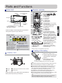 3
3
-
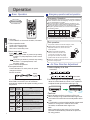 4
4
-
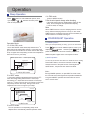 5
5
-
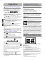 6
6
-
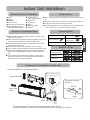 7
7
-
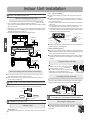 8
8
-
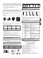 9
9
-
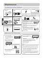 10
10
-
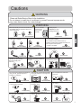 11
11
-
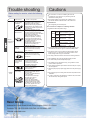 12
12
-
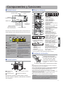 13
13
-
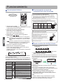 14
14
-
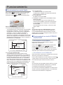 15
15
-
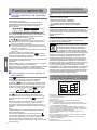 16
16
-
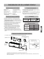 17
17
-
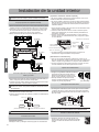 18
18
-
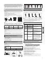 19
19
-
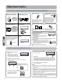 20
20
-
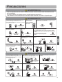 21
21
-
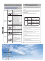 22
22
-
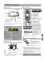 23
23
-
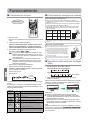 24
24
-
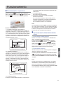 25
25
-
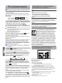 26
26
-
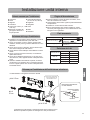 27
27
-
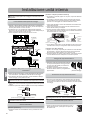 28
28
-
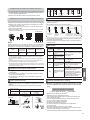 29
29
-
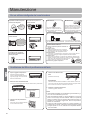 30
30
-
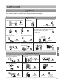 31
31
-
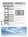 32
32
-
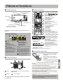 33
33
-
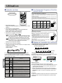 34
34
-
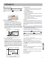 35
35
-
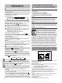 36
36
-
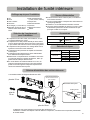 37
37
-
 38
38
-
 39
39
-
 40
40
-
 41
41
-
 42
42
-
 43
43
-
 44
44


Haier AS07GS2ERA - Mode d'emploi
- Catégorie
- Climatiseurs split-system
- Taper
- Mode d'emploi
dans d''autres langues
Documents connexes
-
Haier AF18AS1ERA Le manuel du propriétaire
-
Haier AC362AFEAA Operation and Installation Manual
-
-
Haier AS24GS1ERA Le manuel du propriétaire
-
-
Haier AS07GS1ERA Mode d'emploi
-
-
-
Haier AS07BS4HRA Operation Manual And Installation Manual
-
Autres documents
-
MAXA Tredis Le manuel du propriétaire
-
LG P12EN.NSJ Le manuel du propriétaire
-
Sanyo SAP-CRV246EH Installation Instructions Manual
-
Daikin BRC52B62 Mode d'emploi
-
Immergas ZENITAIR MONO Manuel utilisateur
-
Saunier Duval SDH 31-065 NW Le manuel du propriétaire
-
Beko EFS8000WI Manuel utilisateur
-
aerauliqa Quantum NEXT Mode d'emploi
-
-
Saunier Duval SDH 20-025 NC Le manuel du propriétaire