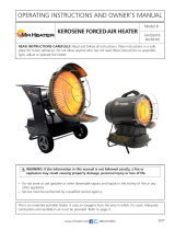
Master 4117.463 XL 9 Le manuel du propriétaire

Taper
Le manuel du propriétaire
XL 9ERM - XL 9SRM
USER AND MAINTENANCE BOOK
MANUEL D’UTILISATION ET DE MAINTENANCE
MP5155
Oil-Burning
Industrial Heater
CONSTRUCTION HEATER GENERAL HAZARD WARNING
READ INSTRUCTIONS CAREFULLY. READ AND FOLLOW ALL INSTRUCTIONS. PLACE INSTRUCTIONS
IN A SAFE PLACE FOR FUTURE REFERENCE. DO NOT ALLOW ANYONE WHO HAS NOT READ THESE
INSTRUCTIONS TO ASSEMBLE, LIGHT, ADJUST OR OPERATE THE HEATER.
IF THE INFORMATION IN THIS MANUAL IS NOT FOLLOWED EXACTLY, A FIRE OR EXPLOSION MAY RE-
SULT CAUSING PROPERTY DAMAGE, PERSONAL INJURY OR LOSS OF LIFE.
SERVICE MUST BE PERFORMED BY A QUALIFIED SERVICE TECHNICIAN.
UNVENTED PORTABLE HEATERS USE MR (OXYGEN) FROM THE AREA IN WHICH IT IS USED. ADEQUA-
TE COMBUSTION AND VENTILATION AIR MUST BE PROVIDED. REFER TO INSTRUCTIONS.
WARNING
FIRE, BURN, INHALATION, AND EXPLOSION HAZARD.
KEEP SOLID COMBUSTIBLES, SUCH AS BUILDING MATERIALS, PAPER OR CARDBOARD, A SAFE DI-
STANCE AWAY FROM THE HEATER AS RECOMMENDED BY THE INSTRUCTIONS. NEVER USE THE
HEATER IN SPACES WHICH DO OR MAY CONTAIN VOLATILE OR AIRBORNE COMBUSTIBLES, OR PRO-
DUCTS SUCH AS GASOLINE, SOLVENTS, PAINT THINNER, DUST PARTICLES OR UNKNOWN CHEMI-
CALS.
WARNING
COMBUSTION BY-PRODUCTS PRODUCED WHEN USING THIS PRODUCT CONTAIN CARBON MONO-
XIDE, A CHEMICAL KNOWN TO THE STATE OF CALIFORNIA TO CAUSE CANCER AND BIRTH DEFECTS
(OR OTHER REPRODUCTIVE HARM).
WARNING
NOT FOR HOME OR RECREATIONAL VEHICLE USE
We cannot anticipate every use which may be made for our heaters. CHECK WITH YOUR LOCAL FIRE SA-
FETY AUTHORITY IF YOU HAVE QUESTIONS ABOUT LOCAL REGULATIONS.
Other standards govern the use of fuel gases and heat producing products in specic applications. Your local
authority can advise you about these.
FOR YOUR SAFETY
DO NOT USE THIS HEATER IN A SPACE WHERE GASOLINE OR OTHER LIQUIDS HAVING
FLAMMABLE VAPORS ARE STORED OR USED.
IMPORTANT
Heater is designed for use as a construction heater. Heater is not intended for use in pest remediation. The
primary purpose of construction heaters is to provide temporary heating of buildings under construction, alte-
ration, or repair and to provide emergency heat. Properly used, the heater provides safe, economical heating.
Products of combustion are vented outside the area being heated.
This heater is designed and approved for use as a construction heater under CSA B140.8 Portable Oil Fired
Heaters; UL 733; UL 296.
We cannot anticipate every use which may be made of our heaters. CHECK WITH YOU LOCAL FIRE
SAFETY AUTHORITY IF YOU HAVE QUESTIONS ABOUT APPLICATIONS.
Other standards govern the use of fuel gases and he at producing products in specic applications. Your local
authority can advise you about these.
AVERTISSEMENTS GÉNÉRAUX DE SÉCURITÉ RELATIFS À L’UNITÉ DE CHAUFFAGE DE
CONSTRUCTION
LIRE ATTENTIVEMENT LES INSTRUCTIONS. LIRE ET SUIVRE LES INSTRUCTIONS. RANGER LES INSTRUCTIONS
DANS UN ENDROIT SÛR POUR CONSULTATION FUTURE. NE PERMETTRE À AUCUNE PERSONNE QUI N’AIT PAS
TOUT D’ABORD LU CES INSTRUCTIONS D’ASSEMBLER, ALLUMER, RÉGLER NI OPÉRER L’UNITÉ DE CHAUFFAGE.
SI LES INFORMATIONS CONTENUES DANS CE MANUEL NE SONT PAS SUIVIES À LA LETTRE, UN INCENDIE OU UNE
EXPLOSION POURRAIT SE PRODUIRE ET CAUSER DES DOMMAGES AUX BIENS, DES LÉSIONS AUX PERSONNES
AVEC RISQUE DE MORT.
LA MANUTENTION DOIT ÊTRE ASSURÉE PAR UN TECHNICIEN DE SERVICE QUALIFIÉ.
LES UNITÉS DE CHAUFFAGE NON VENTILÉES UTILISENT MR (OXYGÈNE) PROVENANT DE L’ENDROIT Oû ILS SONT
UTILISÉS. UNE COMBUSTION ET UNE VENTILATION ADÉQUATES DOIVENT ÊTRE ASSURÉES. SE RÉFÉRER AUX
INSTRUCTIONS.
ATTENTION
DANGER D’INCENDIE, D’INHALATION ET D’EXPLOSION.
CONSERVER LES COMBUSTIBLES SOLIDES, TELS QUE MATÉRIAUX DE CONSTRUCTION, PAPIER OU CARTON À
BONNE DISTANCE DE L’APPAREIL COMME LE RECOMMANDENT LES INSTRUCTIONS. NE JAMAIS UTILISER L’UNITÉ
DE CHAUFFAGE DANS DES ENDROITS CONTENANT OU POUVANT CONTENIR DES COMBUSTIBLES VOLATILES OU
ATMOSPHÉRIQUES, OU DES PRODUITS TELS QU’ESSENCE, SOLVANTS, DILUANTS À PEINTURE, PARTICULES DE
POUSSIÈRE OU PRODUITS CHIMIQUES NON IDENTIFIÉS.
ATTENTION
LES SOUS-PRODUITS DE COMBUSTION PRODUITS LORS DU FONCTIONNEMENT DE CET APPAREIL CONTIENNENT
DU MONOXYDE DE CARBONE, UNE SUBSTANCE CHIMIQUE RECONNUE PAR L’ÉTAT DE CALIFORNIE COMME
SUSCEPTIBLE DE PROVOQUER LE CANCER ET DES ANOMALIES CONGÉNITALES (AINSI QUE D’AUTRES TROUBLES
DE LA REPRODUCTION).
ATTENTION
N’EST PAS ADAPTÉ À L’USAGE DOMESTIQUE NI EN CARAVANE NI DANS D’AUTRES ESPACES
RÉCRÉATIFS
Nous ne pouvons anticiper tous les usages qui pourraient être fait de nos appareils de chauffage. VÉRIFIER AUPRÈS DE
VOS AUTORITÉS DE SÉCURITÉ LOCALES POUR TOUTE QUESTION CONCERNANT LA RÉGLEMENTATION LOCALE.
D’autres normes nationales disciplinent l’emploi des gaz combustibles et des appareils de production de chaleur pour des
applications spéciques. Les autorités locales de votre région peuvent vous fournir les informations opportunes.
POUR VOTRE SÉCURITÉ
NE PAS UTILISER CETTE UNITÉ DE CHAUFFAGE DANS UN ENDROIT OÙ DE L’ESSENCE OU D’AUTRES
LIQUIDES PRODUISANT DES VAPEURS INFLAMMABLES SONT ENTREPOSÉS.
IMPORTANT
L’unité de chauffage est conçue comme un chauffage de construction. L’unité de chauffage n’est pas prévue pour des
procédures d’assainissement. Le but premier des unités de chauffage est de fournir un chauffage temporaire pour des
bâtiments en phase de construction, altération ou réparation et d’apporter de la chaleur en condition d’urgence. Utilisé de
manière appropriée, l’appareil fournit un chauffage sain et économique. Les produits de combustion sont évacués hors de la
zone chauffée.
L’unité de chauffage est conçue et approuvée pour usage en tant qu’Appareil de Chauffage Portable à Combustion de Gas-
oil CSA B140.8; UL 733; UL 296.
Nous ne pouvons anticiper tous les usages qui pourraient être fait de nos appareils de chauffage. VÉRIFIER AUPRÈS DE
VOS AUTORITÉS DE SÉCURITÉ LOCALES POUR TOUTE QUESTION CONCERNANT LES APPLICATIONS.
D’autres normes nationales disciplinent l’emploi des gaz combustibles et des appareils de production de chaleur pour des
applications spéciques. Les autorités locales de votre région peuvent vous fournir les informations opportunes.
100mm
50mm
4106.033-1
This appliance is equipped with a three-prong (grounding) plug for your
protection against electric shock hazard and should be plugged directly
into a grounded three-prong receptacle. - The heater must be grounded. -
The requirements of local authorities having jurisdiction shall be followed.
- This unit is not suitable for use with an external tank. - Do not start the
heater when the chamber is hot. - Do not start the heater when excess oil
has accumulated in the chamber. - Do not use gasoline. - Do not fill the
tank while the unit is operating. - Do not tamper with the unit. Only a
competent service man can make any adjustments. - Use only in open
spaces with good ventilation. - Do not operate the unit in close proximity
to combustible surfaces or materials. - Allow the unit to cool before
shut-down. - Heater intended for dry ambient use only.
WARNING
4106.033-2
Cet appareil est équipé d’une fiche de mise à la terre à trois broches, pour
votre protection contre les chocs électriques et devrait être branchés directe-
ment dans une pris à trois pointes. - L’unité de chauffage doit être mise à la
terre. - Suivre les exigences imposées par les autorités locales ayant juridic-
tion. - Cet appareil n’est pas utilisable avec un réservoir externe. - Ne pas
démarrer l’appareil quand la chambre de combustion est chaude. - Ne pas
démarrer l’appareil quand un excès de gas-oil s’est accumulé dans la chambre
de combustion. - Ne pas utiliser d’essence. - Ne pas remplir le réservoir
quand l’appareil est en fonctionnement. - Ne pas falsifier l’appareil. Seul un
service compétent peut effectuer les réglages. - Pour une bonne ventilation,
l’utiliser en plein air. - Ne pas opérer l’unité à proximité de matériaux ou
surfaces combustibles. - Avant extinction, laisser l’appareil refroidir. -
Chauffage à utiliser dans une ambiance sèche seulement.
AVERTISSEMENT
50mm
100mm
cod: 4106.033
colors:
print white
background black
the red line in cut
CAUTION
When using Thermostat, heater
can start unexpectedly. Turn hea-
ter off when unattended.
ATTENTION
Si connecté au thermostat, le
chauffage peut démarrer à l’im-
proviste. Arrêter le chauffage
laissé sans surveillance.
CAUTION
Ventilation of the room is neces-
sary to prevent a deciency in
oxygen supply.
ATTENTION
Bien ventiler la pièce an d’éviter
un manque d’oxygène.
MODEL XL 9ERM XL 9SRM
146900 Btu/h 99300 Btu/h 146900 Btu/h
1.06 gal/h
P1 0.72 gal/h
P2 1.06 gal/h
K-1 Kerosene
No. 1 or No. 2 Fuel Oil
K-1 Kerosene
No. 1 or No. 2 Fuel Oil
14 gal 14 gal
~120 V 60 Hz 1.7 A ~120 V 60 Hz 1.7 A
158 lb 158 lb
4 - 4.5 4 - 4.5
4 4
0.85 GpH 60°H DANFOSS 0.60 GpH 60°H DANFOSS
145 PSI
1000 kPa
10 bar
145/260 PSI
1000/1800 kPa
10/18 bar
!
IMPORTANT: In order to have a correct function you must use an electrical generator in class G3 or more (frequency variation ±1%,
tension variation ±2%). The maximum power of electrical generator must be three time the nominal power of device that you must connect.
TECHNICAL DATA - TABLEAU DES DONNÉES TECHNIQUES
FUEL PUM ADJUSTMENT - RÉGLAGE DE LA POMPE À CARBURANT
MODEL
MODÈLE
NOZZLE
PISTOLET
PRESSURE
PRESSION
XL 9ERM
DANFOSS 0.85 GpH 60°H 145 PSI 1000 kPa 10 bar
XL 9SRM
DANFOSS 0.60 GpH 60°H 145/260 PSI 1000/1800 kPa 10/18 bar
1
en
USER BOOK
INDEX
2. PRODUCT PRESENTATION
2. UNPACKING AND PACKAGING
3. SAFETY INFORMATION
4. PRODUCT IDENTIFICATION
5. COMBUSTIBLE
5. THEORY OF OPERATION
5. OPERATING INSTRUCTION
5. SAFETY DEVICE
6. MOVING AND TRANSPORTATION
PRODUCT PRESENTATION
XL 9 is a generator of heat by radiation. Radiation technology
is based on the same physical principle behind the warmth
of sunlight. The sun heats bodies without a ow of warm air
but by waves of radiation. The radiation method is becom-
ing highly popular among professional clients because of the
countless advantages it offers. XL 9 was designed on the
basis of this physical principle and has become irreplace-
able in environments which require a constant, even source
of heat for warmth, defrosting and drying. In addition, its ex-
tremely low noise level makes it suitable for working without
having to put up with the noise that other types of heater nor-
mally produce. The generator has rubber wheels for ease
of movement and it can also be raised and set at different
heights by means of eyebolts. Its extended autonomy and
automatic thermostat function grant the operator maximum
freedom of use. The external fuel-tank indicator provides
an easy check on whether fuel needs topping up. The SR
model has a dual power device that enables a more efcient
use of the machine under different conditions and during the
various seasons of the year.
UNPACKING AND PACKAGING
UNPACKING
• Remove the supports used to pack the appliance (Fig. 1).
• Open top side of the box.
• Remove the cardboard from the top.
• Remove the supports that hold the generator to the pallet
(Fig. 2).
• Delicately lower the heater off the pallet.
• Dispose of the material used to pack the generator ac-
cording to the current government regulations in your
area.
• Check the machine for eventual damages incurred during
transportation, if the machine appears damaged immedi-
ately inform the store where you purchased it.
ON PACKAGING AND STORING
WARNING: The packaging material is not a toy.
Keep the plastic bag out of the reach of children;
danger of suffocation!
If the generator needs to be placed in storage, or if it
has suffered major damage in transport, or needs to be
repaired:
• Check for damage, in particular of a nature which could
cause loss of fuel. In this case, empty the tank of the
remaining fuel.
• For storage, place the generator on the same pallet from
which it was unpacked and, for return, on any suitable
EPA-branded euro-pallet.
• Firmly anchor the generator to the pallet (Fig. 2).
Whenever possible, slide the cardboard packing from
the top down over the pallet and anchor it rmly using
suitable materials (Fig. 1).
• Store the machine in a suitable, dry place and do not
stack more than two. Despatch the generator preferably
as shown Fig. 1 or at least as shown in Fig. 2.
Figur 1 - Packaging
Figur 2 - On pallett
2
en
IMPORTANT: READ AND UNDERSTAND THIS OPERATIONAL MANUAL
BEFORE PERFORMING ASSEMBLY, COMMISSIONING OR MAINTENANCE
ON THIS HEATER. INCORRECT USE OF THE HEATER CAN CAUSE SERIOUS
INJURY. KEEP THIS MANUAL FOR FURTHER REFERENCE.
3
en
SAFETY INFORMATION
WARNING
!
IMPORTANT: This appliance is not suitable for
use by persons (including children) with reduced
physical, sensory and mental capacities or with
lack of experience or knowledge unless supervised
by a person responsible for their safety. Children
must be supervised to make sure they do not play
with the appliance.
!
DANGER: Suffocation by carbon monoxide
can be fatal.
!
IMPORTANT: The installation of this heater for
use with No. 1, No. 2, Diesel or Kerosene and shall
conform with local codes.
!
IMPORTANT: THE INSTALLATION OF THE
UNIT SHALL BE IN ACCORDANCE WITH THE
REGULATIONS OF THE AUTHORITIES HAVING
JURIS DICTION.
The rst symptoms of suffocation by carbon monoxide are
similar to those of u with headache, light-headedness
and/or nausea. These symptoms could be caused by the
faulty functioning of the heater. IF THESE SYMPTOMS
OCCUR, GO OUTDOORS IMMEDIATELY and have the
heater repaired by a technical service centre.
►►2.1. REFUELLING:
►2.1.1. Personnel appointed to carry out refuelling must
be qualied and fully familiar with this manual and current
regulations on how to refuel heaters safely.
►2.1.2. Only use the type of fuel specied on the heaters
identication plate.
►2.1.3. Before refuelling, turn off the heater and wait for
it to cool down.
►2.1.4. The fuel storage deposit tanks must be located in
a separate facility or building.
►2.1.5. All fuel tanks must be kept at a minimum distance
from the heater, in accordance with current safety regula-
tions.
►2.1.6. Fuel must be stored in areas where the oor
surface does not allow underneath dripping, or any other
leakage which may ignite the fuel.
►2.1.7. Fuel must be stored in accordance with current
safety regulations.
►►2.2. SAFETY:
►2.2.1. Never use the heater in areas with petrol, paint
solvents or other highly ammable vapours.
►2.2.2. Comply with all local legislation and current regu-
lations when using the heater.
►2.2.3. Heaters used near tarpaulins, curtains or other
similar covering materials must be kept at a safe distance.
It is advised to use re-proof covering material.
►2.2.4. Only use heaters in well-ventilated areas. Set-up
a suitable open and ventilated area, with the purpose of
introducing fresh air from outdoors, in compliance with the
current safety standards.
►2.2.5. Heaters must be powered only with the correct
voltage and frequency values as specied on the heaters
identication plate.
►2.2.6. Only use suitable earthed extension cable. 115v
supply must be available. Please note that the heater re-
quires 15 amps for proper operation. Ensure appropriate
gauge extension cord is used. (12/3 AWG at 50 Ft. - 10/3
AWG at 100 Ft.).
►2.2.7. The recommended safety distances between
heaters and ammable substances are: front output = 5
ft.; side/top/rear output = 2 ft..
►2.2.8. Avoid re hazards by placing the hot or function-
ing heater on a at level surface.
►2.2.9. Always keep animals at a safe distance.
►2.2.10. Disconnect the heater from the main power sup-
ply when not in use.
►2.2.11. When controlled by a thermostat, the heater can
turn on at any time.
►2.2.12. Never use the heater in frequently used rooms
or in bedrooms.
►2.2.13. Never block the heater’s air inlet (rear) or the air
outlet (front).
►2.2.14. Never move, handle, refuel or conduct mainte-
nance on the heater when it is hot or when connected to
the power supply or when in operation.
►2.2.15. Keep heater’s hot parts at as safe distance from
inammable materials (including the power supply cable).
►2.2.16. If the power supply cable is damaged, it must be
replaced by a technical service centre, in order to prevent
further risks.
PRODUCT IDENTIFICATION
A. Combustion chamber, B. Hole for raising generator, C.
Fuel lter or pre-heated lter (optional), D. Fuel supply, E.
Fuel Return, F. Fuel tank cap, G. Foot or wheel (optional),
H. Fuel level indicator, I. Block of the group combustion,
L. Radiant deector, M. Fuel drain plug, N. Fuel tank, O.
Handle to move the generator, P. Hinge block, Q. Burner,
R. Inclination regulator
A.
B.
C.
D.
E.
F.
G.
H.
I.
R.
Q.
P.
O.
N.
M.
L.
Figur 3
Figur 4
A.
B.
C.
D.
E.
G.
H.
F.
R.
I.
D.
L.
M.
N1.
O1.
Q.
T.
S.
P.
U1.
U2.
U1.
N2.
N2.
O2.
Figur 5 - Function controls
Figur 6 - Components burner
A. Air vent regulator, B. Lighted ON/OFF button, C. ON/
OFF switch depending on power option (XL 9SRM), D.
RESET Button, E. Power indicator, F. Burner coffer, G.
Thermostat plug, H. Screw for burner block, I. Post-ven-
tilation device, L. Flame control device, M. Transformer,
N1. Pressure regulator (XL 9ERM) of the pump, N2. Pres-
sure regulator (XL 9SRM) of the pump, O1. (XL 9ERM)
fuel pump, O2. (XL 9SRM) fuel pump, P. Condenser, Q.
Motor, R. Burner tube, S. Combustion head regulator ,
T. Photo-resistance, U1. Electrovalve ame step (XL
9ERM-SR), U2. Electrovalve 2° ame step (XL 9SRM)
4
en
5
en
COMBUSTIBLE
WARNING: The heater only works with No. 1, No. 2,
Diesel or Kerosene.
The use of impure combustible can cause:
• Blockage of the combustible lter and nozzle.
• Formation of carbonaceous deposits on the electrodes.
At low temperatures use non-toxic antifreeze.
THEORY OF OPERATION
The ventilation needed for proper combustion is produced
by a fan inside the burner. The air exits the burner sleeve
and mixes with the fuel which is nebulised by a high-pres-
sure nozzle. The fuel is aspirated from the fuel tank by
a rotary pump which forces it at high pressure up to the
nozzle for nebulisation.
OPERATING INSTRUCTIONS
WARNING: Before putting the generator in function,
and therefore before connecting it to the electrical
system, you must check to see if the electrical sys-
tems technical characteristics correspond to those
on the identication plate of the generator.
STARTING THE GENERATOR
1. Follow all of the safety information.
2. Fill the tank with diesel fuel or kerosene.
3. Close the fuel cap.
4. Plug the alimentation cord into a grounded wall plug with
the same tension as the one written on the generators
identication plate.
STARTING WITHOUT A THERMOSTAT
• XL 9ERM
Set the switch (B Fig. 5) to the ON position (I). It begins
the period of pre-ventilation and after approximately 10
seconds ones the combustion has beginning.
• XL 9SRM
WARNING: Before starting the generator to make
sure that the button (C Fig. 5) is in position
.
Set the switch (B Fig. 5) to the ON position (I). It begins
the period of pre-ventilation and after approximately 10
second ones the combustion has beginning.
For having the maximum potentiality portare set the
switch (C Fig. 5) to the
position.
STARTING WITH A THERMOSTAT
Regulate the thermostat or the control device (for exam-
ple a timer), if connected, so that it will allow the generator
to function.
WARNING: The generator can ONLY function
automatically when the control device, for example
a Thermostat or a Timer, is connected to the
generator. To connect the control device to the
machine consult the paragraph entitled “ELECTRIC
DIAGRAM”.
Before starting the machine or after the fuel line has been
completely emptied, the fuel ow to the nozzle should be
insufcient to cause the intervention of the security device
which controls the ame (see the “SAFETY DEVICE”
paragraph) that stops the generator. In this case, after
having waited approximately one minute, push the Reset
button (D Fig. 5 and 6) and start the machine.
If the machine isn’t working you should rst control the
following:
1. Make sure that the fuel tank (N Fig. 4) still contains fuel.
2. Press the Restart button (D Fig. 5 and 6).
If the generator still isn’t functioning consult the “FAULTS
AND THEIR LIKELY CAUSES” paragraph to identify the
cause.
WARNING: Before the second ignition (machine
extinguished and adequately cold) to assure the
blocking of the screws that block the anterior de-
ector (L Fig. 4).
WARNING: The electric power that feeds the
generator must be grounded and have a differential
magnetic-thermal switch. The generators electric
cord must be attached to a plug equipped with a
section switch.
TURNING THE GENERATOR OFF
Turn the switch (B Fig. 5) to the OFF position (O) or turn
the thermostat or control device (timer) off if there is one
connected. The ame will go out and the ventilation will
continue until it has nished its post-ventilation cycle
(cooling down).
WARNING: Before unplugging the alimentation cord
from the wall, wait until the post-ventilation cycle
is completely nished (it will take approximately 3
minutes to cool down).
SAFETY DEVICE
The generator is equipped with a safety device (L Fig. 6),
which controls the ame. If one or more anomalies occur
when the generator is functioning, the device will block
the burner and the RESET button (D Fig. 5 or 6) will light
up.
The generator also has a post-ventilation device which
enables optimal, automatic cooling of the combustion
chamber for some 3 minutes.
Before turning the generator on again you must identify
and eliminate the cause that blocked the machine.
MOVING AND TRANSPORTATION
NOTICE: Before raising or moving the machine
ensure that the fuel tank caps (F and H Fig. 3) are
rmly closed.
TRANSPORT
The generator is easy to move and it may be xed in a
raised position thanks to its special eye-bolt mechanism
(B Fig. 3 or Fig. 7). This enables it to be set in the most
suitable position for heating, defrosting and drying.
MOVEMENT
Before picking up or moving the machine you must check
to insure that the tank caps (G Fig. 3) are tightly shut. The
generator may be supplied with a rotating wheel. In this
case, if the ooring allows it you may push the generator
like a cart. In the case the machine does not have rotat-
ing wheels it is necessary to unblock the hinge (P Fig.
4) located on one of the lateral struts of the generator.
Lower the handle from its “resting position” (Fig. 8) Turn
the handle to the “transportation position” (Fig. 9). Lift the
generator and position it so that it is resting on the two
anterior wheels.
WARNING: Before moving the machine you must:
turn the machine off by following the indications
provided in paragraph “TURNING OFF THE HEAT-
ER”; unplug the electrical source by pulling the
plug out of the wall and waiting for the generator to
cool down.
Figur 8 - Position close handles
Figur 9 - Position open handles
6
en
Figur 7 - Hooks in order to raise
1
MAINTENANCE BOOK
WARNINGS!!!
Only use kerosene or diesel to avoid any fire or explosion hazard.
Never use petrol, naphtha, paint solvents or other highly flammable fuels.
Never use this heater near petrol, solvents for colours or vapours from highly flammable fuels.
Follow all local ordinances and provisions when using the heater.
Only use in well-ventilated areas.
Only use in places that are free from inflammable vapours and that do not contain heavy dust.
Only use with the electrical frequency and voltage specified in the user manual.
Only use the three-pole power supply cable with earthing.
Avoid fire hazards by positioning the hot or functioning heater on a steady, level surface.
When moving or storing the heater, it must be in a level position to avoid any fuel leak.
Keep children and animals away from the heater.
Disconnect the heater from the electrical power supply when not in use.
This device can operate with a room thermostat. When connected to the electrical power supply,
the heater may turn on at any moment.
Never obstruct the air flow entering (behind) or exiting (front).
Do not handle, lift, refuel, or repair the heater if it is hot, in operation or if connected to the
electrical power supply.
Never attach ducts on the front or rear part of the heater.
3
2 - Introduction
This part of the manual contains information and repair procedures that help personnel in charge understand
and correct problems. The first part contains basic information regarding operations carried out by various
parts of the heater. It provides basic knowledge on how the main components work during heater operation.
The second part covers resolving any problems and there is a quick reference manual regarding conditions
resulting from customer complaints. These procedures will help personnel in charge of repairs quickly
diagnose the problem.
Preparations before making repairs
A clean work area is essential for an effective repair operation. Clean extremely dirty heaters before repairing
them. Sometimes cleaning the machine will highlight the problem. A set of tools is necessary to carry out the
repair. Searching for the necessary tools causes delays that lead to loss of time and money.
Always use clean fuel when testing the heater. Many problems originate from the use of unsuitable or dirty
fuel. Use caution and good sense when working on a heater and always remember:
That kerosene and diesel are inflammable so handle them with care;
Watch out for thermal shock;
Because some parts of the heater get hot during operation. Touching these parts may cause severe
burns.
R
equired tools
In addition to common workshop tools, Customer Service should have the following items and tools to repair
the heater.
Figure 1 - Multimeter. Figure 2 - Feeler gauge. Figure 3 - Manometer.
4
3 - General information
Electrical power supply
Connect the heater to a power socket having the same voltage and frequency as that specified on the
identification plate. For safety reasons, all power supply cables are equipped with a three-pole plug with
earth. If extension cords are use, be careful not to exceed the length. Make sure that the extension cord used
is sized for the voltage that the heater needs to operate correctly.
V
entilating the environment
Only use the heater in well ventilated rooms. Increase the ventilation if multiple heaters are used in the same
room. Remember that these types of heaters may produce carbon monoxide, a substance that can cause
serious poisoning and, in some cases, even death.
Sizing the heater
The thermal power of the heater is calculated based on the volume to be heated. Below is a simple formula
that can be used to define the heater's power.
5
4 - Functions of the components
There are four basic systems that make up the heater: the fuel system, the ventilation system, the ignition
system and the flame control system.
Fuel system: The pump takes fuel from the tank and pressurises it. It pushes it through the filter and
the pump to make it exit as a very fine mist from the nozzle in the combustion head.
Ventilation system: The motor turns the fan. It pushes air into the combustion chamber. The air
entering the combustion chamber mixes with the fuel mist for combustion. The flame that is created
lightly touches the internal wall of the combustion chamber. This chamber reaches a temperature
that is so high that the front baffle becomes incandescent, heating anything in front of it by radiation.
Ignition system: The transformer sends voltage to the electrodes that ignite the mixture of air and
fuel.
Flame control system: This system causes the machine to turn off if the flame is interrupted. Upon
subsequent ignition, the equipment must be reset manually.
Electrical system: This system allows heater operation, in all of its parts, as soon as it is connected
to suitable mains voltage that conforms to that shown on the heater's identification plate.
Fuel system
As shown in the fuel system diagram below, the fuel is taken in by the pump in the burner. The fuel passes
from a rigid pipe and continues up to the line filter. Here the fuel is filtered by a cartridge, pressurised and
sent at suitable pressure to the nozzle. At the nozzle, the fuel is filtered a third time before being suitably
vaporised.
FUEL SYSTEM DIAGRAM
A.
B.
C.
D.
E.
H
A. Burner, B. Fuel Supply pipe, C. Fuel Filter, D. Fuel Return pipe, E. Fuel Tank.
6
Fuel filter
A.
B.
C.
D.
Figure 4 - Fuel line filter.
A. Series of gaskets, B. Fuel output infeed body, C. Filtering element (Cartridge), D. Plastic cup.
This is a cup filter containing a filtering element and a series of gaskets, all elements that can easily be
replaced. This element is very important because it keeps tiny particles from reaching the nozzle, and
thereby clogging it or even ruining it definitively.
F
uel filter maintenance
If the heater works in abrupt movements, one of the possible causes may be the filter. To clean the filter,
unscrew the plastic cup and clean it using clean fuel and compressed air. The filtering element must be
removed and cleaned using compressed air.
Fuel pump
The fuel system may be equipped with two different pumps depending on the type of machine being
analysed. Both pumps can work either with diesel oil or kerosene. When the motor starts turning, the pump
starts working, beginning to suction fuel from the intake pipe. As soon as the fuels enters the pump it is
pressurised and a portion, managed by one or two solenoid valves (respectively single stage and double
stage), is forcibly channelled to the nozzle through the supply pipe and the excess portion is re-channelled
towards the tank through the return pipe (double pipe mode).
Pump for XL 9ERM
Figure 5 - Single solenoid valve pump.
A. Filtering element, B. Solenoid valve, C. Seat for the filtering element, D. Manometer attachment, E. Pump
pressure adjustment screw.
7
Pump adjustment
To adjust the fuel pressure for the XL 9ERM heater,
use the specific adjustment screw (E Fig. 5). Turning
the screw clockwise increases the pressure, turning it
in the opposite direction decreases it.
Remember that information on adjusting the pump
pressure can be found in the manual. To check if the
pump pressure is correct, connect the manometer to
the pressure plug (D Fig. 5). The pressure must be adjusted by a qualified person. Incorrect adjustment may
result in improper combustion.
P
ump for XL 9SRM
Figure 6 - Double solenoid valve pump.
A. Filtering element, B. Solenoid valve 1st flame stage, C. Seat for the filtering element, D. Manometer
attachment, E. First stage pressure adjustment screw, F. Second stage pressure adjustment screw, G.
Solenoid valve 2nd flame stage.
Pump adjustment
To adjust the fuel pressure to the XL 9SRM heater, turn the two adjustment screws. When the appliance
operates in the 1st flame stage, turn the adjustment screw (E Fig. 6). When the appliance operates in the 2nd
flame stage, turn the fixing screw (F Fig. 6). Turning the adjustment screw (E Fig. 6) is all that is needed.
Turning the screw clockwise increases the pressure, turning it in the opposite direction decreases it.
Remember that there are two pump pressures for this model. Remember that information on adjusting the
pump pressure can be found in the manual. To check if the pump pressures are correct, connect the the
manometer to the pressure plug (D Fig. 6). The pressure must be adjusted by a qualified person. Incorrect
adjustment may result in improper combustion.
ATTENTION!!!
Before passing from one fuel to another, drain
all the fuel from the tank as well as the hydraulic
system. Before starting the machine a second
time, carefully clean the line filter, the pump
filter and the nozzle.
ATTENTION!!!
Before passing from one fuel to another, drain
all the fuel from the tank as well as the hydraulic
system. Before starting the machine a second
time, carefully clean the line filter, the pump
filter and the nozzle.
8
Figure 7 - Pump joint.
The pump is connected to the motor shaft through a plastic pump joint shown here on the side. This
component safeguards the motor operation if the pump were to seize up. In this case, the stall torque would
effectively increase along with the absorbed current and the pump joint, breaking, would avoid further
damage to the motor.
S
olenoid valve
The solenoid valve is an electromagnetic device. It is integrated in the fuel pump and its purpose is to
intercept the flow of fuel going from the pump to the nozzle. When the flame control appliance gives consent,
the solenoid valve is powered and therefore opens, allowing the fuel to reach the nozzle, otherwise, when the
machine is turned off, the solenoid valve is no longer powered and therefore closes, blocking the fuel flow and
therefore interrupting the flame. There are two solenoid valve models based on the type of power supply.
Figure 8 - Solenoid valve integrated in the fuel pump.
Fuel pump maintenance
If the fuel does not reach the nozzle, it may be that the pump has seized and/or that the joint is broken. In this
case, loosen the three screws blocking the pump and verify the condition of the pump joint. Make sure that
the pump has not seized up. If the joint is broken, replace it with an original joint according to the type of
motor. If the pump's shaft has seized, replace it. If the pump starts to squeal and does not working correctly,
it may be that the filtering element is clogged. Proceed by removing it (see Fig. 5 and Fig. 6) and clean it
using clean fuel. Make sure that the fuel used to wash the filter is the same type of fuel used for the heater
operation. If it is not available, use compressed air. Be careful not to ruin the filtering element structure. Pay
attention when performing repairs on the pump because it works at high pressure.
IMPORTANT: If the pump joint breaks, replace it
with an original spare part.
9
Nozzle
The nozzle can be defined for all intents and purposes as the heart of the combustion system. The operation
of the entire machine depends on its correct operation. The fuel passes through it and, under the effect of the
pump pressure, it expands through the outlet, becoming finely vaporised.
Figure 9 - Nozzle for diesel oil and kerosene.
The nozzle has data written on it such as the flow, in US Gal/hr or Kg/hr, that leaves the outlet at a
conventional pressure.
N
ozzle maintenance
Figure 10 - Cleaning the nozzle with a jet of air into the outlet.
Never replace the nozzle with one having different characteristics. Always use original spare parts. If the
nozzle is not working correctly, clean it using compressed air as shown in the figure.
The nozzle type is defined based on the type of heater (SEE TABLE).
Tightening torques
Oil Nozzle Type
Reference
Capacity
Us gal/hr
Spray angles/patterns
60°
Specified
Capacity
Us gal/hr
0.85
H
1.11
0.60
H
0.76 - 1.11
Recommended
tightening torques
15 to 20 Nm
(1.5 to 2.0 kpm)
Max. tightening torques
25Nm (2.5 kpm)
  • Page 1 1
  • Page 2 2
  • Page 3 3
  • Page 4 4
  • Page 5 5
  • Page 6 6
  • Page 7 7
  • Page 8 8
  • Page 9 9
  • Page 10 10
  • Page 11 11
  • Page 12 12
  • Page 13 13
  • Page 14 14
  • Page 15 15
  • Page 16 16
  • Page 17 17
  • Page 18 18
  • Page 19 19
  • Page 20 20
  • Page 21 21
  • Page 22 22
  • Page 23 23
  • Page 24 24
  • Page 25 25
  • Page 26 26
  • Page 27 27
  • Page 28 28
  • Page 29 29
  • Page 30 30
  • Page 31 31
  • Page 32 32
  • Page 33 33
  • Page 34 34
  • Page 35 35
  • Page 36 36
  • Page 37 37
  • Page 38 38
  • Page 39 39
  • Page 40 40
  • Page 41 41
  • Page 42 42
  • Page 43 43
  • Page 44 44
  • Page 45 45
  • Page 46 46
  • Page 47 47
  • Page 48 48
  • Page 49 49
  • Page 50 50
  • Page 51 51
  • Page 52 52
  • Page 53 53
  • Page 54 54
  • Page 55 55
  • Page 56 56
  • Page 57 57
  • Page 58 58
  • Page 59 59
  • Page 60 60
  • Page 61 61
  • Page 62 62
  • Page 63 63
  • Page 64 64
  • Page 65 65
  • Page 66 66
  • Page 67 67
  • Page 68 68
  • Page 69 69
  • Page 70 70
  • Page 71 71
  • Page 72 72
  • Page 73 73
  • Page 74 74
  • Page 75 75
  • Page 76 76
  • Page 77 77
  • Page 78 78
  • Page 79 79
  • Page 80 80
  • Page 81 81
  • Page 82 82

Master 4117.463 XL 9 Le manuel du propriétaire

Taper
Le manuel du propriétaire

dans d''autres langues