NAPOLEON GSST8P Manuel utilisateur
- Catégorie
- Cheminées
- Taper
- Manuel utilisateur
Ce manuel convient également à

1
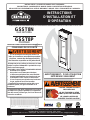
W415-0689 / D / 08.23.18
INSTALLER: LEAVE THIS MANUAL WITH THE APPLIANCE.
CONSUMER: RETAIN THIS MANUAL FOR FUTURE REFERENCE.
NEVER LEAVE CHILDREN OR OTHER AT RISK INDIVIDUALS ALONE WITH THE APPLIANCE.
INSTALLATION AND
OPERATING INSTRUCTIONS
1.22B
Wolf Steel Ltd., 24 Napoleon Rd., Barrie, ON, L4M 0G8 Canada /
103 Miller Drive, Crittenden, Kentucky, USA, 41030
Phone (705)721-1212 • Fax (705)722-6031 • www.napoleonfi replaces.com • [email protected]
SAFETY INFORMATION
!
WARNING
If the information in these instructions are
not followed exactly, a fi re or explosion
may result causing property damage,
personal injury or loss of life.
- Do not store or use gasoline or other fl ammable
vapors and liquids in the vicinity of this or any
other appliance.
- WHAT TO DO IF YOU SMELL GAS:
• Do not try to light any appliance.
• Do not touch any electrical switch; do not use
any phone in your building.
• Immediately call your gas supplier from a
neighbour’s phone. Follow the gas supplier’s
instructions.
• If you cannot reach your gas supplier, call the
fi re department.
- Installation and service must be performed by a
qualifi ed installer, service agency or the supplier.
CERTIFIED FOR CANADA AND UNITED STATES USING ANSI/CSA METHODS.
$10.00
HOT GLASS WILL CAUSE
BURNS.
DO NOT TOUCH GLASS UNTIL
COOLED.
NEVER ALLOW CHILDREN TO
TOUCH GLASS.
!
WARNING
This appliance is only for use with the type of gas
indicated on the rating plate. This appliance is
not convertible for use with other gases, unless a
certifi ed kit is used.
GSST8N
NATURAL GAS
GSST8P
PROPANE
CERTIFIED UNDER CANADIAN AND AMERICAN NATIONAL STANDARDS: CR97-003 ● CAN-2.21-M85 ● IAS US. 4-96
WARNING: FOR OUTDOOR USE ONLY

2
W415-0689 / D / 08.23.18
NOTE: Changes, other than editorial, are denoted by a line in the margin.
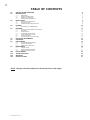
TABLE OF CONTENTS
1.0 INSTALLATION OVERVIEW 3
2.0 INTRODUCTION 4
2.1 DIMENSIONS 5
2.2 GENERAL INSTRUCTIONS 5
2.3 GENERAL INFORMATION 6
2.4 RATING PLATE INFORMATION 7
3.0 INSTALLATION 8
3.1 INSTALLATION CLEARANCES 8
3.2 GAS INSTALLATION 9
3.3 COMBUSTION AND VENTILATION AIR 9
4.0 FRAMING 10
4.1 CLEARANCES TO COMBUSTIBLES 10
5.0 FINISHING 11
5.1 TMCSS MOUNTING CABINET INSTALLATION 11
5.2 RAIN TABS 12
5.3 DOOR REMOVAL 13
5.4 GLASS MEDIA INSTALLATION 14
5.5 TFSSO FRAME INSTALLATION 15
5.6 LOGO PLACEMENT 15
5.7 LK8 LIGHT INSTALLATION (OPTIONAL) 16
6.0 ELECTRICAL INFORMATION 17
7.0 OPERATION 18
8.0 ADJUSTMENTS 19
8.1 GAS PRESSURE ADJUSTMENT 19
8.2 VENTURI ADJUSTMENT 19
8.3 FLAME CHARACTERISTICS 19
9.0 MAINTENANCE 20
9.1 CARE OF GLASS 20
9.2 DOOR GLASS REPLACEMENT 21
9.3 CARE OF STAINLESS STEEL 21
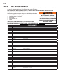
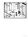
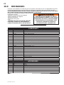
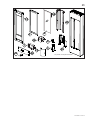
10.0 REPLACEMENTS 22
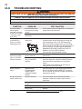
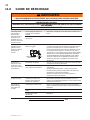
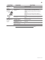
11.0 TROUBLESHOOTING 24
12.0 WARRANTY 26
13.0 SERVICE HISTORY 27

3
W415-0689 / D / 08.23.18
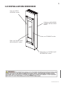
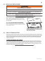
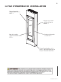
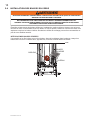
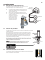
1.0 INSTALLATION OVERVIEW
Cabinet, see “MOUNTING
CABINET INSTALLATION”
section.
Door, see “DOOR
REMOVAL” section.
Glass, see “DOOR GLASS
REPLACEMENT” section.
Frame, see “FRAMING” section.
Rating plate, see “RATING PLATE
INFORMATION” section.

4
W415-0689 / D / 08.23.18
3.14A
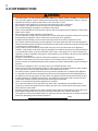
!
WARNING
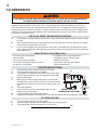
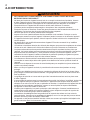
• THIS APPLIANCE IS HOT WHEN OPERATED AND CAN CAUSE SEVERE BURNS IF CONTACTED.
• Do not operate appliance before reading and understanding operating instructions. Failure to operate
appliance according to operating instructions could cause fi re or injury.
• Any changes to this appliance or its controls can be dangerous and is prohibited.
• Risk of burns. The appliance should be turned off and cooled before servicing.
• Do not install damaged, incomplete or substitute components.
• Risk of cuts and abrasions. Wear protective gloves and safety glasses during installation. Sheet metal
edges may be sharp.
• Do not burn wood or other materials in this appliance.
• Provide adequate ventilation and combustion air. Provide adequate accessibility clearance for servicing
and operating the appliance. Never obstruct the front opening of the appliance.
• If appliance keeps shutting off, have it serviced. Keep burner and control compartment clean.
• Do not allow wind to blow directly into the appliance. Avoid any drafts that alter burner fl ame patterns.
• Children and adults should be alerted to the hazards of high surface temperature and should stay away
to avoid burns or clothing ignition.
• Young children should be carefully supervised when they are in the same area as the appliance.
Toddlers, young children and others may be susceptible to accidental contact burns. A physical barrier
is recommended if there are at risk individuals in the vicinity of the appliance. To restrict access to an
appliance, install an adjustable safety gate to keep toddlers, young children and other at risk individuals
away from hot surfaces.
• Clothing or other fl ammable material should not be placed on or near the appliance.
• Furniture or other objects must be kept a minimum of 4 feet away from the front of the appliance.
• Ensure you have incorporated adequate safety measures to protect infants/toddlers from touching hot
surfaces.
• Even after the appliance is off, it will remain hot for an extended period of time.
• Check with your local hearth specialty dealer for safety screens and hearth guards to protect children
from hot surfaces. These screens and guards must be fastened to the fl oor.
• Any safety screen or guard removed for servicing must be replaced prior to operating the appliance.
• It is imperative that the control compartments, burners and circulating blower and its passageway in
the appliance and venting system are kept clean. The appliance should be inspected before use and
at least annually by a qualifi ed service person. The appliance area must be kept clear and free from
combustible materials, gasoline and other fl ammable vapors and liquids.
• Under no circumstances should this appliance be modifi ed.
• Do not use this appliance if any part has been under water. Immediately call a qualifi ed service
technician to inspect the appliance and to replace any part of the control system and any gas control
which has been under water.
• Keep the packaging material out of reach of children and dispose of the material in a safe manner. As
with all plastic bags, these are not toys and should be kept away from children and infants.
• This appliance must not be installed indoors or within any structure that prevents or inhibits the exhaust
gases from dissipating in the outside atmosphere.
2.0 INTRODUCTION

5
W415-0689 / D / 08.23.18
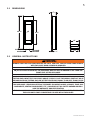
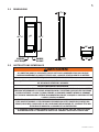
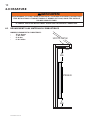
2.1 DIMENSIONS
2.2 GENERAL INSTRUCTIONS
49
11
/
16
”
GAS LINE
ACCESS
ELECTRICAL
ACCESS
6 Ǫ”
1 ½”
15”
13”
7
9
/
16
”
ALWAYS LIGHT THE PILOT WHETHER FOR THE FIRST TIME OR IF THE GAS SUPPLY HAS RAN OUT,
WITH THE GLASS DOOR OPENED OR REMOVED.
NEVER OBSTRUCT THE FRONT OPENING OF THE APPLIANCE.
OBJECTS PLACED IN FRONT OF THE APPLIANCE MUST BE KEPT A MINIMUM OF 48” FROM THE
FRONT FACE OF THE APPLIANCE.
FIRE RISK. EXPLOSION HAZARD.
HIGH PRESSURE WILL DAMAGE VALVE. DISCONNECT GAS SUPPLY PIPING BEFORE PRESSURE
TESTING GAS LINE AT TEST PRESSURES ABOVE 1/2 PSIG. CLOSE THE MANUAL SHUT-OFF VALVE
BEFORE PRESSURE TESTING GAS LINE AT TEST PRESSURES EQUAL TO OR LESS THAN 1/2 PSIG.
USE ONLY WOLF STEEL APPROVED OPTIONAL ACCESSORIES AND REPLACEMENT PARTS WITH
THIS APPLIANCE. USING NON-LISTED ACCESSORIES (BLOWERS, DOORS, LOUVRES, TRIMS, GAS
COMPONENTS, VENTING COMPONENTS, ETC.) COULD RESULT IN A SAFETY HAZARD AND WILL
VOID THE WARRANTY AND CERTIFICATION.
THE APPLIANCE IS ONLY FOR USE WITH THE TYPE OF GAS INDICATED ON THE RATING PLATE.
THIS APPLIANCE IS NOT CONVERTIBLE FOR USE WITH OTHER GASES.
!
WARNING

6
RATES AND EFFICIENCIES
NATURAL GAS PROPANE GAS
Altitude 0 - 4,500* 0 - 4,500*
Maximum Input 6,000 6,000
Minimum Inlet Gas Supply Pressure 4.5” Water Column 11” Water Column
Maximum Inlet Gas Supply Pressure 7” Water Column 13” Water Column
Manifold Pressure Under Flow Conditions 3.5” Water Column 10” Water Column
4.3A
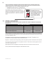
THIS GAS APPLIANCE SHOULD BE INSTALLED AND SERVICED BY A QUALIFIED INSTALLER to
conform with local codes. Installation practices vary from region to region and it is important to know the
specifi cs that apply to your area, for example in Massachusetts State:
• The appliance off valve must be a “T” handle gas cock.
• The fl exible connector must not be longer than 36 inches.
The installation must conform with local codes or, in
absence of local codes, the National Gas and Propane
Installation Code CSA B149.1 in Canada, or the National
Fuel Gas Code, ANSI Z223.1 / NFPA 54 in the United
States.
We suggest that our gas
hearth products be installed
and serviced by professionals
who are certied in the U.S.
by the National Fireplace
Institute
®
(NFI) as NFI Gas
Specialists
www.ncertied.org
2.3 GENERAL INFORMATION
FOR YOUR SATISFACTION, THIS APPLIANCE HAS BEEN TEST-FIRED TO ENSURE ITS OPERATION
AND QUALITY!
When the appliance is installed at elevations above 4,500ft, and in the absence of specifi c recommendations
from the local authority having jurisdiction, the certifi ed high altitude input rating shall be reduced at the rate of
4% for each additional 1,000ft.
This appliance is only for use with the type of gas indicated on the rating plate. This appliance is not
convertible for use with other gases, unless a certifi ed kit is used.
Expansion / contraction noises during heating up and cooling down cycles are normal and are to be expected.
Purge all gas lines with the glass door of the appliance removed. Ensure that a continuous gas fl ow is at the
burner before replacing the door.
Objects placed in front of the appliance must be kept a minimum of 48” from the front face of the unit.
Use only authorized accessories designed for and listed with the model.
W415-0689 / D / 08.23.18

7
W415-0689 / D / 08.23.18
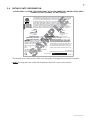
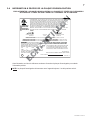
2.4 RATING PLATE INFORMATION
RATING LABEL LOCATION: THE RATING LABEL IS LOCATED UNDER THE CONTROL PANEL AND IS
CHAINED TO THE APPLIANCE. DO NOT REMOVE.
CERTIFIED UNDER : CGA CR97-003 (July, 1997) CSA US Req. 4-96, 3rd Ed. OUTDOOR GAS FIREPLACE
IF APPLIANCE HAS BEEN SUPPLIED WITH A GAS PRESSURE REGULATOR, IT MUST BE USED.
THE GAS SUPPLY MUST BE TURNED OFF AT THE LP-GAS SUPPLY CYLINDER WHEN THIS
APPLIANCE IS NOT IN USE. DO NOT STORE OR USE GASOLINE OR OTHER FLAMMABLE
VAPORS AND LIQUIDS IN THE VICINITY OF THIS OR ANY OTHER APPLIANCE. IMPROPER
INSTALLATION, ADJUSTMENT, ALTERATION, SERVICE OR MAINTENANCE CAN CAUSE INJURY
OR PROPERTY DAMAGE. REFER TO THE OWNER’S MANUAL PROVIDED WITH THIS
APPLIANCE. FOR ASSISTANCE OR ADDITIONAL INFORMATION, CONSULT A QUALIFIED
INSTALLER, SERVICE AGENCY OR GAS SUPPLIER. MUST NOT BE USED FOR COOKING. FOR
OUTDOOR USE ONLY. IF STORED INDOORS, DETACH AND LEAVE CYLINDER OUTDOORS.
ALTITUDE
INPUT
MANIFOLD PRESSURE: 3.5" WATER COLUMN
MINIMUM SUPPLY PRESSURE: 4.5" WATER COLUMN
MAXIMUM SUPPLY PRESSURE: 7.0" WATER COLUMN
MANIFOLD PRESSURE: 10" WATER COLUMN
MINIMUM SUPPLY PRESSURE: 11" WATER COLUMN
MAXIMUM SUPPLY PRESSURE: 13" WATER COLUMN
0-4500FT (0-1370m)
6,000 BTU/h
0-4500FT (0-1370m)
6,000 BTU/h
GSST8N
MODEL
GSST8P
MODEL
W385-0420 / E
GSST8
NOT FOR USE WITH SOLID FUEL. FOR USE
WITH
GLASS DOOR. CERTIFIED WITH THIS UNIT ONLY.
WARNING: DO NOT ADD ANY MATERIAL TO THE
APPLIANCE, WHICH WILL COME IN CONTACT WITH THE
FLAMES, OTHER THAN THAT SUPPLIED BY THE
MANUFACTURER WITH THE APPLIANCE.
MINIMUM CLEARANCES TO COMBUSTIBLE MATERIALS
TOP 18” BACK 0”
SIDES 1” FLOOR 8”
SERIAL NUMBER:
ELECTRICAL RATING: 115v 0.82AMP, 60HZ
TOP
, SIDES & BACK AS PER ABOVE. FOR FINISHING
MATERIAL, SEE OWNERS MANUAL.
(NATURAL GAS) (PROPANE)
THIS APPLIANCE IS ONLY FOR USE WITH THE TYPE
OF GAS INDICATED ON THE RATING PLATE. THIS
APPLIANCE IS NOT CONVERTIBLE FOR USE WITH
OTHER GASES, UNLESS A CERTIFIED KIT IS USED.
WOLF STEEL LTD.
24 NAPOLEON ROAD. BARRIE, ONTARIO L4M 0G8 CANADA
9700539 (WSL)
4001657 (NGZ)
4001658 (NAC)
4001659 (WUSA)
Ed. OUTDOOR Gd. OUTDOOR
EGULATOR, IT MUSEGULATOR, IT MU
UPPLY CYLINDER WHENPPLY CYLINDER WHEN
OLINE OR OTHER FLAMMABL
NE OR OTHER FLAMMABL
Y OTHER APPLIANCE. IMPROPAPPLIANCE. IMPROP
E OR MAINTENANCE CAN CAUANCE CAN CAU
S MANUAL PROVIDED WITH THS MANUAL PROVIDED WITH T
L INFORMATION, CONSULT A QUINFORMATION, CONSULT A Q
PLIER. MUST NOT BE USED FOR. MUST NOT BE USED F
RS, DETACH AND LEAVE CYLINS, DETACH AND LEAVE CYLIN
A
A
LL
TITUDETITUDE
LL
I
I
NN
P
P
U
T
AA
TERT
AA
CO
L
U
M
COLUM
NN
WW
AA
WWW
TERTER
AAA
CO
L
U
M
COLUM
NN
7.0"0"
WW
AA
WWW
TERTER
AAA
CO
L
U
M
COLUM
NN
M
ANIFOL
DMANIFOLD
PP
MINIMUMMINIMU
S
MAXIMAXIM
L
MM
OO
D
Y MATERIAL TO THE RIAL TO THE
ME IN CONTACT WITH THEME IN CONTACT WITH THE
AT SUPPLIED BY THE AT SUPPLIED BY THE
THE APPLIANCE.HE APPLIANCE.
CES TO COMBUSTIBLE MATERO COMBUSTIBLE MATE
BACKCK
FLOORFLOOR
RICAL RATING: 115v 0.82AMP,
AL RATING: 115v 0.82AMP
& BACK AS PER ABOVE. FOR & BACK AS PER ABOVE. FO
L, SEE OWNERS MANUAL.
SEE OWNERS MANUAL.
SAMPLE
This illustration is for reference only. Refer to the rating plate on the appliance for accurate information.
NOTE: The rating plate must remain with the appliance at all time. It must not be removed.

8
W415-0689 / D / 08.23.18
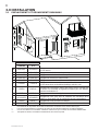
3.0 INSTALLATION
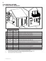
3.1 INSTALLATION CLEARANCES
G
G
J
I
K
A
C
D
E
F
H
B
B
INSTALLATIONS
CANADA U.S.A.
A 8 INCHES 8 INCHES Clearance above grade, veranda porch, deck or balcony.
B 12 INCHES 9 INCHES Clearance to windows or doors that open.
C 12 INCHES* 12 INCHES* Clearance to permanently closed windows.
D 18 INCHES** 18 INCHES** Vertical clearance to ventilated soffi t.
E 12 INCHES** 12 INCHES** Vertical clearance to an unventilated soffi t.
F 1 INCH 1 INCH
Clearance to an inside combustible corner wall or protruding
combustible obstructions. (vent chase, etc.)
G 3 FEET 3 FEET***
Clearance to each side of the centre line extended above the metre/
regulator assembly to a maximum vertical distance of 15 ft.
H 3 FEET 3 FEET*** Clearance to a service regulator vent outlet.
I 12 INCHES 9 INCHES
Clearance to a non-mechanical air supply inlet to the building or a
combustion air inlet to any other appliance.
J 6 FEET 3 FEET**** Clearance to a mechanical air supply inlet.
K 12 INCHES 12 INCHES*** Clearance under a veranda, porch, deck or balcony.
* Recommended to prevent condensation on windows and thermal breakage.
** It is recommended to use a heat shield and to maximize the distance to vinyl clad soffi ts.
*** This is a recommended distance. For additional requirements check local codes.
**** Three feet above if within 10 feet horizontally.

9
W415-0689 / D / 08.23.18
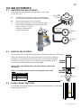
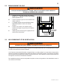
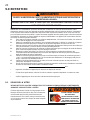
3.2 GAS INSTALLATION
A. The appliance is designed to accept a 1/2” gas
supply line. The appliance is equipped with a 1/2”
manual shut-off valve.
B. The access to the gas inlet is located in the bottom
of the cabinet.
C. The shut off valve / fl ex connector assembly must
always be contained within the cabinet.
D. When fl exing any gas line, support the gas valve
so that the lines are not kinked.
E. Check for gas leaks by brushing on a soap and
water solution.
W385-0380
SHUT OFF
VALVE
FLEX
CONNECTOR
!
WARNING
ALL GAS CONNECTIONS MUST BE CONTAINED WITHIN THE APPLIANCE WHEN COMPLETE.
DO NOT USE OPEN FLAME.
This appliance is intended for installation on an outdoor patio or in your yard. It must never be installed inside
the warm air envelope of your structure.
It is highly recommended that this appliance be installed in a “sheltered” area. Direct wind will cause an erratic
fl ame and possible pilot or main burner outage. An erratic fl ame could also lead to excessive carboning (black
soot), this condition is not a safety issue but is visually undesirable.
Typical installation may include covered patio, screened porch, gazebo, or on an outside wall of a house.
3.3 COMBUSTION AND VENTILATION AIR
!
WARNING
ENSURE THE AREA HAS ADEQUATE VENTILATION.

10
W415-0689 / D / 08.23.18
!
WARNING
YOUR APPLIANCE IS DESIGNED FOR OUTDOOR APPLICATION ONLY. THE APPLIANCE MUST
BE INSTALLED IN THE CABINET PROVIDED. THE CABINET IS DESIGNED TO BE INSTALLED ON
FINISHED SURFACES.
THE CABINET MAY BE INSTALLED DIRECTLY ONTO A COMBUSTIBLE SURFACE.
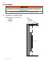
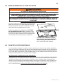
4.0 FRAMING
MINIMUM CLEARANCES TO COMBUSTIBLES:
- 18” to top
- 1” to sides
- 8” to bottom
- 0” to rear
4.1 CLEARANCES TO COMBUSTIBLES
24”
MAX.
18”
MIN.
OUTDOOR
8”
MIN.
VENTILLATED
SOFFIT

11
W415-0689 / D / 08.23.18
5.0 FINISHING
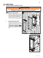
5.1 TMCSS MOUNTING CABINET INSTALLATION
INSTALLATION
TEMPLATE
TORCH
MOUNTING
FRAME
CABINET
1
NOTE: It is recommended that all fasteners be
stainless steel.
A. Using the installation template (W122-0401)
supplied, determine the best mounting location
for your new Torch. (Refer to your manual for
clearances) Mark all 14 hole centres on the
wall (surface) using the template.
B. Remove the template. Depending on the
surface and fasteners, drill the appropriate
holes. Hold the Torch up, aligning the
mounting brackets to the mounting holes.
Secure the Torch to the wall using the
appropriate fasteners. NOTE: The Torch has
been designed to have a 1/2” clearance
between the rear outer panel and the
mounting surface.
!
WARNING
BEFORE STARTING THE INSTALLATION, REMOVE THE PROTECTIVE LAYER FROM ALL THREE
COMPONENTS THAT MAKE UP THE GSST8 (CABINET, FRAME AND TORCH).
2
MOUNTING
BRACKET

12
W415-0689 / D / 08.23.18
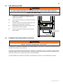
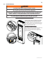
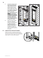
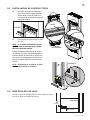
5.2 RAIN TABS
9
0
º
60
º
RAIN
TAB
When shipped, the rain tabs should be at a 90º
angle. Push the rain tabs down until they are at an
approximate 60º angle to assist rain in running off and
out of the unit.
4
3
KEYHOLE
C. Start the fasteners into each
of the six remaining mounting
holes. Align the keyholes of
the frame to the heads of the
fasteners and slide the frame
down onto the fasteners.
Ensure the frame is plumb
and level before tightening
the fasteners. NOTE: It is
recommended that the gas
and electrical be connected
to the appliance at this
stage. Both must enter the
appliance at the opening
created between the bottom
of the Torch and the bottom
of the mounting frame.
D. Slide the front of the cabinet
over the mounting frame,
ensuring the “mesh” is to the
top. Start each of the four
screws (supplied) through the
slots. Once the cabinet has
been adjusted for depth the
four screws can be tightened.

13
W415-0689 / D / 08.23.18
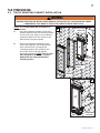
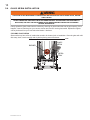
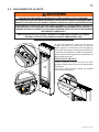
5.3 DOOR REMOVAL
!
WARNING
GLASS MAY BE HOT, DO NOT TOUCH GLASS UNTIL COOLED.
THE DOOR LATCHES ARE PART OF A SAFETY SYSTEM AND MUST BE PROPERLY ENGAGED. DO
NOT OPERATE THE APPLIANCE WITH LATCHES DISENGAGED.
FACING AND/OR FINISHING MATERIALS MUST NOT INTERFERE WITH AIR FLOW THROUGH AIR
OPENINGS, LOUVRES OPENINGS, OPERATION OF LOUVRES OR DOORS OR ACCESS FOR
SERVICE. OBSERVE ALL CLEARANCES WHEN APPLYING COMBUSTIBLE MATERIALS.
BEFORE DOOR IS REMOVED TURN THE APPLIANCE OFF AND WAIT UNTIL APPLIANCE IS COOL TO
THE TOUCH. DOORS ARE HEAVY AND FRAGILE SO HANDLE WITH CARE.
75.1
B
O
T
T
O
M
D
O
O
R
R
E
T
A
I
N
E
R
T
O
P
D
O
O
R
F
L
A
N
G
E
SECURING THE DOOR IN PLACE
When shipped, the door is secured with two hitch pins
along the top edge, replacing them is optional.
To secure the door in place use the supplied hitch
pins as illustrated.
HITCH PIN
The door is held in place at the bottom by a retainer
tab that inserts into a slot in the bottom edge of the
door, and at the top with a tab that secures in the
same fashion. The door is removed by lifting it off the
tabs. When replacing, guide the door over the upper
tab fi rst, then over the lower tab.

14
W415-0689 / D / 08.23.18
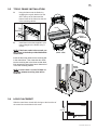
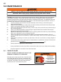
5.4 GLASS MEDIA INSTALLATION
74.2A
Evenly spread the glass media onto the media tray, ensuring no glass media falls into the pilot opening. If this
happens, insert a clean bag into your vacuum cleaner and vacuum out the glass media. Replacement glass
can be purchased from your local authorized dealer / distributor.
CLEANING GLASS MEDIA
Glass media may have a fi ne oil residue that needs to be cleaned prior to installation. Clean the glass with mild
dish soap, drain, rinse thoroughly and dry before placing around the burner.
CLEAN THE GLASS MEDIA PRIOR TO INSTALLATION. BEFORE APPLYING THE CLEANED GLASS, ENSURE
THAT IT IS DRY.
DO NOT CHANGE OR SUBSTITUTE THE GLASS MEDIA MATERIAL PROVIDED WITH THIS APPLIANCE. IF
REPLACING, USE ONLY THE REPLACEMENT GLASS MEDIA AVAILABLE FROM YOUR AUTHORIZED
DEALER / DISTRIBUTOR.
!
WARNING
MEDIA
TRAY
GLASS
MEDIA
BURNER

15
W415-0689 / D / 08.23.18
1/4”
(APPROX.)
CONTROL
DOOR
1/4”
(APPROX.)
LOGO
With the control door closed, affi x the logo to the front face of
the control door at the bottom left corner.
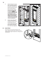
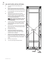
5.5 TFSSO FRAME INSTALLATION
DOOR
CHAIN
SLOT
FRAME
(REAR VIEW)
TRIM
BRACKET
TRIM
BRACKET
5.6 LOGO PLACEMENT
A. Hang the frame onto the fi rebox by
engaging the top trim bracket into the
slot in the top of the frame and the
bottom hooks of the frame into the slot
in the mounting cabinet.
B. Install the trim bracket supplied in your
manual baggie to the fi rebox using 3
screws.
NOTE: If the frame needs to be secured, use
two screws in the holes provided behind the
control door.
Insert the door stop chain into the receiving slot
in the control door.
Then insert the door chain
into the receiving slot in the frame so that when
fully opened the control door has a clearance of
1/8” to the mounting cabinet.
NOTE: In most cases a count of 15 balls on
the chain between receiving slots will be
suffi cient.

16
W415-0689 / D / 08.23.18
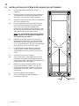
A. Turn off the electrical and gas supply to the
appliance.
B. Remove the frame from the unit by removing the 2
stainless steel hex head securing screws from the
bottom and lifting the frame off of the top trim bracket.
C. Lay the frame down on its front, being careful not to
scratch the fi nish.
D. Starting at the top of the frame, take one light
assembly and carefully snap it into place in the hole
provided. Repeat for each of the light assemblies.
The wires on the top 2 light assemblies will need to
be fed in behind the heat shields.
NOTE: When installing the light kit be careful not
to scratch your fi ngers on any of the exposed
screws in the frame.
E. Connect the light assemblies to the appropriate fl ags
on the wire harness. The wire harness is labeled
(TR) top right, (BR) bottom right (TL) Top left and
(BL) bottom left.
F. Secure the wires into the clips at both sides and the
bottom of the frame. Use the extra clips provided to
retain any loose wires.
G. Re-attach frame onto unit.
H. Open the control panel door, leave the wires
connected to the ON/OFF switch and place the
transformer into the bottom of the unit. Plug the
transformer into the receptacle.
I. Attach one of the wire leads from the transformer to
the lead on the wire harness labeled “TRANS”, and
the other to the ON/OFF switch. Attach the last lead
on the wire harness labeled “SWI” to the ON/OFF
switch.
J. Close the control panel door.
K. Turn on the gas supply and electrical power.
TR
TL
TRANS
SWI
CLIPS X 5
BR
BL
5.7 LK8 LIGHT INSTALLATION (OPTIONAL)

17
W415-0689 / D / 08.23.18
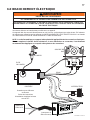
It is necessary to hard wire this appliance.
This appliance must be electrically connected and grounded in accordance with local codes. In the absence
of local codes, use the current CSA C22.1 Canadian Electrical Code in Canada or the ANSI/NFPA 70-1996
national electrical code in the United States.
NOTE: During assembly, anti-oxidant compound was applied to all electrical connections. If replacing
the existing wire harness or disconnecting any connectors, it is highly recommended to re-apply anti-
oxidant compound to the relative connections.
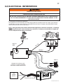
6.0 ELECTRICAL INFORMATION
!
WARNING
RISK OF ELECTRIC SHOCK!
CONTROL AND VALVE OPERATE WITH 110V.
DO NOT USE THIS APPLIANCE IF ANY PART HAS BEEN UNDER WATER. CALL A QUALIFIED SER-
VICE TECHNICIAN IMMEDIATELY TO HAVE THE APPLIANCE INSPECTED FOR DAMAGE TO THE
ELECTRICAL CIRCUIT.
12
34
YELLOW
BROWN
W
+
,
7
E
B
L
$
&
.
IGNITOR
WIRE
IGNITOR
GAS
VALVE
SWITCH
CONTROL MODULE
110v
POWER
SUPPLY
GFI
(Ground Fault Interrupter)
G
R
O
U
N
D
Illustration for reference only.
Follow the complete installation
instructions included with the GFI.
RESET
TEST

18
W415-0689 / D / 08.23.18
Ensure that a continuous gas fl ow is at the burner before installing the door. When lit for the fi rst time, the
fi replace will emit an odor for a few hours. This is a normal temporary condition caused by the “burn-in” of
paints and lubricants used in the manufacturing process and will not occur again. After extended periods of
non-operation such as following a vacation or a warm weather season, the fi replace may emit a slight odor for
a few hours. This is caused by dust particles in the heat exchanger burning off. In both cases, open a window
to suffi ciently ventilate the room.
FOR YOUR SAFETY READ BEFORE LIGHTING:
A. This fi replace is equipped with an ignition device which automatically lights the pilot. Do not try to light
by hand.
B. Before operating smell all around the fi replace area for gas and next to the fl oor because some gas is
heavier than air and will settle on the fl oor.
C. Do not use this fi replace if any part has been under water. Immediately call a qualifi ed service techni-
cian to inspect the fi replace and replace any part of the control system and any gas control which has
been under water.
WHAT TO DO IF YOU SMELL GAS:
• Turn off all gas to the fi replace.
• Open windows.
• Do not try to light any appliance.
• Do not touch any electric switch; do not use
any phone in your building.
• Immediately call your gas supplier from
a neighbour’s phone. Follow the gas
supplier’s instructions.
• If you cannot reach your gas supplier,
call the fi re department.
LIGHTING INSTRUCTIONS:
1. Stop! Read the above safety information on this label.
2. Turn off all electrical power to the fi replace.
3. This fi replace is equipped with an ignition device which auto-
matically lights the pilot. Do not try to light the pilot by hand.
4. Open the glass door.
5. Wait fi ve (5) minutes to clear out any gas. If you smell gas
including near the fl oor, STOP! Follow “B” in the above safety
information on this label. If you don’t smell gas go to the next
step.
6. Close the glass door.
7. Turn on all electric power to the fi replace and re-install
batteries into the transmitter.
8. Turn the fi replace switch to the ON position.
9. If fi replace will not operate, follow instructions “To Turn Off Gas” and call your service technician or gas supplier.
1. Turn the fi replace switch to the OFF position.
2. Turn off all electrical power to the fi replace if service is to be performed.
3. Turn manual shut-off valve clockwise to off. Do not force.
TO TURN OFF GAS:
47.8
O
S
MANUAL SHUT-OFF
(SHOWN IN OFF POSITION)
A
IF YOU DO NOT FOLLOW THESE INSTRUCTIONS EXACTLY, A FIRE OR EXPLOSION MAY RESULT
CAUSING PROPERTY DAMAGE, PERSONAL INJURY OR LOSS OF LIFE.
!
WARNING
7.0 OPERATION

19
W415-0689 / D / 08.23.18
8.0 ADJUSTMENTS
8.1 GAS PRESSURE ADJUSTMENT
Outlet pressure can be adjusted if not measuring 3.5” W.C. (NG)
or 10.0” W.C. (LP).
A. Pressure can be checked by removing cap (A) using a
3/16 Allen key and replacing it with a 1/8 NPT barb fi tting.
B. Place pressure gauge tube over the fi tting.
C. Pressure can be adjusted by removing cap (B) using a
fl at screwdriver, and adjusting the nylon plug with the
same screw driver. Turning
the plug in (clockwise) will
increase the pressure.
1/8”
1/4”
A
1/8
NPT BARB
FITTING
10
PROPANE
GAS
PRESSURE
GAUGE
NATURAL
GAS
3.5
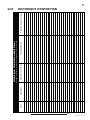
8.2 VENTURI ADJUSTMENT
This model has an air shutter that has been factory set open according to the chart below:
Closing the air shutter will cause a more yellow fl ame, but can lead to carboning.
Opening the air shutter will cause a more blue fl ame, but can cause fl ame lifting
from the burner ports. The fl ame may not appear yellow immediately; allow 15
to 30 minutes for the fi nal fl ame color to be established.
A
IR SHUTTER ADJUSTMENT MUST ONLY BE DONE BY A QUALIFIED
INSTALLER!
NOTE: It is important that the venturi sits down tight on the orifi ce.
49.3
VENTURI
BURNER
AIR
SHUTTER
OPENING
AIR SHUTTER OPENINGS
LP 3/16” DIA
NG 1/16” DIA
8.3 FLAME CHARACTERISTICS
It is important to periodically perform a visual check of the burner fl ame. Compare them
to the illustration provided.

20
W415-0689 / D / 08.23.18
• Visually inspect the appliance for carbon buildup.
• Using a small whisk or brush, brush off the excess carbon and vacuum up or sweep into the garbage.
• Check the fi replace for corrosion of the main burner base.
9.0 MAINTENANCE
CAUTION: Label all wires prior to disconnection when servicing controls. Wiring errors can cause improper
and dangerous operation. Verify proper operation after servicing. This appliance and its venting system
should be inspected before use and at least annually by a qualifi ed service person. The appliance area must
be kept clear and free of combustible materials, gasoline or other fl ammable vapors and liquids. The fl ow of
combustion and ventilation air must not be obstructed.
A. In order to properly clean the burner and pilot assembly, remove the logs, rocks and/or glass to
expose both assemblies.
B. Keep the control compartment, media, burner, air shutter opening and the area surrounding the logs
clean by vacuuming or brushing, at least once a year.
C. Check to see that all burner ports are burning. Clean out any of the ports which may not be burning or
are not burning properly.
D. Check to see that the pilot fl ame is large enough to engulf the fl ame sensor and/or thermocouple /
thermopile as well as reaches the burner.
E. Replace the cleaned logs, rocks or glass. Failure to properly position the media may cause carboning
which can be distributed in the surrounding living area.
F. Check to see that the main burner ignites completely on all openings when turned on. A 5 to 10
second total light-up period is satisfactory. If ignition takes longer, consult your local authorized dealer /
distributor.
G. Check that the gasketing on the sides, top and bottom of the door is not broken or missing. Replace if
necessary.
H. If for any reason the vent air intake system is disassembled, re-install and re-seal per the instructions
provided for the initial installation.
40.1
MAINTENANCE
MAINTENANCE
MAINTENANCE
TURN OFF THE GAS AND ELECTRICAL POWER BEFORE SERVICING THE APPLIANCE.
APPLIANCE MAY BE HOT, DO NOT SERVICE UNTIL APPLIANCE HAS COOLED.
DO NOT USE ABRASIVE CLEANERS.
!
WARNING
9.1 CARE OF GLASS
5.1
DO NOT CLEAN GLASS WHEN HOT! DO NOT USE
ABRASIVE CLEANERS TO CLEAN GLASS.
Buff lightly with a clean dry soft cloth. Clean both sides
of the glass after the fi rst 10 hours of operation with a
recommended fi replace glass cleaner. Thereafter clean
as required. If the glass is not kept clean permanent
discoloration and / or blemishes may result.
HOT GLASS WILL
CAUSE BURNS.
DO NOT TOUCH GLASS
UNTIL COOLED.
NEVER ALLOW CHILDREN
TO TOUCH GLASS.
!
WARNING
La page est en cours de chargement...
La page est en cours de chargement...
La page est en cours de chargement...
La page est en cours de chargement...
La page est en cours de chargement...
La page est en cours de chargement...
La page est en cours de chargement...
La page est en cours de chargement...
La page est en cours de chargement...
La page est en cours de chargement...
La page est en cours de chargement...
La page est en cours de chargement...
La page est en cours de chargement...
La page est en cours de chargement...
La page est en cours de chargement...
La page est en cours de chargement...
La page est en cours de chargement...
La page est en cours de chargement...
La page est en cours de chargement...
La page est en cours de chargement...
La page est en cours de chargement...
La page est en cours de chargement...
La page est en cours de chargement...
La page est en cours de chargement...
La page est en cours de chargement...
La page est en cours de chargement...
La page est en cours de chargement...
La page est en cours de chargement...
La page est en cours de chargement...
La page est en cours de chargement...
La page est en cours de chargement...
La page est en cours de chargement...
La page est en cours de chargement...
La page est en cours de chargement...
La page est en cours de chargement...
La page est en cours de chargement...
-
 1
1
-
 2
2
-
 3
3
-
 4
4
-
 5
5
-
 6
6
-
 7
7
-
 8
8
-
 9
9
-
 10
10
-
 11
11
-
 12
12
-
 13
13
-
 14
14
-
 15
15
-
 16
16
-
 17
17
-
 18
18
-
 19
19
-
 20
20
-
 21
21
-
 22
22
-
 23
23
-
 24
24
-
 25
25
-
 26
26
-
 27
27
-
 28
28
-
 29
29
-
 30
30
-
 31
31
-
 32
32
-
 33
33
-
 34
34
-
 35
35
-
 36
36
-
 37
37
-
 38
38
-
 39
39
-
 40
40
-
 41
41
-
 42
42
-
 43
43
-
 44
44
-
 45
45
-
 46
46
-
 47
47
-
 48
48
-
 49
49
-
 50
50
-
 51
51
-
 52
52
-
 53
53
-
 54
54
-
 55
55
-
 56
56


NAPOLEON GSST8P Manuel utilisateur
- Catégorie
- Cheminées
- Taper
- Manuel utilisateur
- Ce manuel convient également à
dans d''autres langues
- English: NAPOLEON GSST8P User manual
Documents connexes
-
NAPOLEON GSS36N Manuel utilisateur
-
-
-
-
-
-
-
NAPOLEON LVX62N2X Manuel utilisateur
-
-