
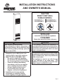
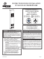
INSTALLATION INSTRUCTIONS
AND OWNER’S MANUAL
Page 1
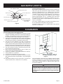
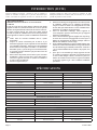
FAN TYPE
DIRECT
-
VENT WALL
FURNACE MODEL:
DVC35IPXLP-1 DVC35SPPXLP-1
DVC35IPXNAT-1
DVC35SPPXNAT-1
This appliance may be installed in an aftermarket,
permanently located manufactured home (USA
only) or mobile home, where not prohibited by
state or local codes.
This appliance is only for use with the type
of gas indicated on the rating plate. This
appliance is not convertible for use with other
gases, unless a certied kit is used.
WARNING
FIRE OR EXPLOSION HAZARD
If the information in these instructions is
not followed exactly, a re or explosion may
result causing property damage, personal
injury or loss of life.
— Do not store or use gasoline or other
ammable vapors and liquids in the
vicinity of this or any other appliance.
— WHAT TO DO IF YOU SMELL GAS
• Do not try to light any appliance.
• Do not touch any electrical switch;
do not use any phone in your building.
• Leave the building immediately.
• Immediately call your gas supplier
from a neighbor’s phone. Follow
the gas supplier’s instructions.
• If you cannot reach your gas
supplier, call the re department.
— Installation and service must be
performed by a qualied installer,
service agency or the gas supplier.
INSTALLER:
Leave this manual with the appliance.
CONSUMER:
Retain this manual for future reference.
WARNING
If not installed, operated and maintained in
accordance with the manufacturer's instructions,
this product could expose you to substances in
fuel or from fuel combustion which can cause
death or serious illness.

37402-5-0620Page 2
TABLE OF CONTENTS
Important Safety Information ......................................................................................................... 3
Safety Information for Users of Propane Gas ............................................................................... 4
Requirements for Massachusetts .................................................................................................. 5
Introduction.................................................................................................................................6-7
Specications ................................................................................................................................ 7
Gas Supply .................................................................................................................................8-9
Clearances .................................................................................................................................... 9
Installation Instructions ........................................................................................................... 10-12
DVC-35SPP Standing Pilot Lighting Instructions ........................................................................ 13
DVC-35IP Intermittent Pilot Lighting Instructions ........................................................................ 14
Pilot Flame Characteristics.......................................................................................................... 15
Main Burner Flame Characteristics ............................................................................................. 16
Wiring .......................................................................................................................................... 16
Service and Maintenance Suggestions ....................................................................................... 17
DVC-35IP Intermittent Pilot Sequence of Operation ................................................................... 18
DVC-35IP Intermittent Pilot System Troubleshooting Sequence ................................................ 19
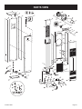
Parts List ..................................................................................................................................... 20
Parts View ................................................................................................................................... 21
Master Parts Distributor List ........................................................................................................ 22
How To Order Repair Parts ......................................................................................................... 22
Warranty ...................................................................................................................................... 23
SECTION PAGE

37402-5-0620 Page 3
IMPORTANT SAFETY INFORMATION
THIS IS A HEATING APPLIANCE
DO NOT OPERATE THIS APPLIANCE WITHOUT FRONT PANEL INSTALLED.
• Due to high temperatures, the appliance should be
located out of trafc and away from furniture and
draperies.
• Children and adults should be alerted to the hazards
of high surface temperatures and should stay away
to avoid burns or clothing ignition.
• Young children should be carefully supervised when
they are in the same room as the appliance.
• Clothing or other ammable material should not be
placed on or near the appliance.
• Any safety screen or guard removed for servicing
an appliance must be replaced prior to operating
the appliance.
• Keep burner and control compartment clean.
• Vent cap hot while furnace is in operation.
• Installation and repair should be done by a QUALI-
FIED SERVICE PERSON. The appliance should be
inspected before use and at least annually by a
qualied service person. More frequent cleaning
may be required due to excessive lint from carpet-
ing, bedding materials, etc. It is imperative that
control compartments, burners and circulating air
passageways of the appliance be kept clean.
• DO NOT put anything around the furnace that will
obstruct the ow of combustion and ventilation air.
• DO keep the appliance area clear and free from
combustible material, gasoline and other ammable
vapors and liquids.
• DO examine venting system periodically and replace
damaged parts.
• DO make a periodic visual check of pilot and burn-
ers. Clean and replace damaged parts.
• CAUTION: Pilot hole cover must be kept tightly
closed during operation.
• DO NOT use this heater if any part has been under
water. Immediately call a qualied service techni-
cian to inspect the heater and to replace any part of
the control system and any gas control which has
been under water.
IMPORTANT: This furnace has a washable permanent
type lter which should be cleaned at least once per
year before the heating season. For dirty or high use
areas, more frequent cleaning is required.

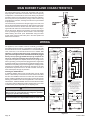
37402-5-0620Page 4
SAFETY INFORMATION FOR USERS OF PROPANE GAS
Propane is a ammable gas which can cause res and explo-
sions. In its natural state, propane is odorless and colorless.
You may not know all the following safety precautions which
can protect both you and your family from an accident. Read
them carefully now, then review them point by point with the
members of your household. Someday when there may not
be a minute to lose, everyone’s safety will depend on knowing
exactly what to do. If, after reading the following information,
you feel you still need more information, please contact your
gas supplier.
PROPANE GAS WARNING ODOR
If a gas leak happens, you should be able to smell the gas
because of the odorant put in the Propane Gas. That’s your
signal to go into immediate action!
• Do not operate electric switches, light matches, use your phone.
Do not do anything that could ignite the gas.
• Get everyone out of the building, vehicle, trailer, or area. Do
that IMMEDIATELY.
• Close all gas tank or cylinder supply valves.
• Propane Gas is heavier than air and may settle in low areas
such as basements. When you have reason to suspect a gas
leak, keep out of basements and other low areas. Stay out
until reghters declare them to be safe.
• Use your neighbor’s phone and call a trained Propane Gas
service person and the re department. Even though you may
not continue to smell gas, do not turn on the gas again. Do not
re-enter the building, vehicle, trailer, or area.
• Finally, let the service man and reghters check for escaped
gas. Have them air out the area before you return. Properly
trained Propane Gas service people should repair the leak,
then check and relight the gas appliance for you.
NO ODOR DETECTED - ODOR FADE
Some people cannot smell well. Some people cannot smell
the odor of the chemical put into the gas. You must nd out if
you can smell the odorant in propane. Smoking can decrease
your ability to smell. Being around an odor for a time can affect your
sensitivity or ability to detect that odor. Sometimes other odors in
the area mask the gas odor. People may not smell the gas odor or
their minds are on something else. Thinking about smelling a gas
odor can make it easier to smell.
The odorant in Propane Gas is colorless, and it can fade under
some circumstances. For example, if there is an underground
leak, the movement of the gas through soil can lter the odorant.
Odorants in Propane Gas also are subject to oxidation. This fading
can occur if there is rust inside the storage tank or in iron gas pipes.
The odorant in escaped gas can adsorb or absorb onto or into
walls, masonry and other materials and fabrics in a room. That will
take some of the odorant out of the gas, reducing its odor intensity.
Propane Gas may stratify in a closed area, and the odor intensity
could vary at different levels. Since it is heavier than air, there may
be more odor at lower levels. Always be sensitive to the slightest gas
odor. If you detect any odor, treat it as a serious leak. Immediately
go into action as instructed earlier.
SOME POINTS TO REMEMBER
• Learn to recognize the odor of Propane Gas. Your local Propane
Gas Dealer can give you a “Scratch and Sniff” pamphlet. Use
it to nd out what the propane odor smells like. If you suspect
that your Propane Gas has a weak or abnormal odor, call your
Propane Gas Dealer.
• If you are not qualied, do not light pilot lights, perform service,
or make adjustments to appliances on the Propane Gas system.
If you are qualied, consciously think about the odor of Propane
Gas prior to and while lighting pilot lights or performing service
or making adjustments.
• Sometimes a basement or a closed-up house has a musty
smell that can cover up the Propane Gas odor. Do not try to
light pilot lights, perform service, or make adjustments in an
area where the conditions are such that you may not detect
the odor if there has been a leak of Propane Gas.
• Odor fade, due to oxidation by rust or adsorption on walls of
new cylinders and tanks, is possible. Therefore, people should
be particularly alert and careful when new tanks or cylinders
are placed in service. Odor fade can occur in new tanks, or
reinstalled old tanks, if they are lled and allowed to set too
long before relling. Cylinders and tanks which have been out
of service for a time may develop internal rust which will cause
odor fade. If such conditions are suspected to exist, a periodic
sniff test of the gas is advisable. If you have any question
about the gas odor, call your Propane Gas Dealer. A peri-
odic sniff test of the Propane Gas is a good safety measure
under any condition.
• If, at any time, you do not smell the Propane Gas odorant and
you think you should, assume you have a leak. Then take the
same immediate action recommended above for the occasion
when you do detect the odorized Propane Gas.
• If you experience a complete “gas out,” (the container is under
no vapor pressure), turn the tank valve off immediately. If the
container valve is left on, the container may draw in some air
through openings such as pilot light orices. If this occurs, some
new internal rusting could occur. If the valve is left open, then
treat the container as a new tank. Always be sure your con-
tainer is under vapor pressure by turning it off at the container
before it goes completely empty or having it relled before it is
completely empty.

37402-5-0620 Page 5
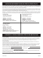
REQUIREMENTS FOR MASSACHUSETTS
For all side wall horizontally vented gas fueled equipment installed
in every dwelling, building or structure used in whole or in part for
residential purposes, including those owned or operated by the
Commonwealth and where the side wall exhaust vent termination
is less than seven (7) feet above nished grade in the area of the
venting, including but not limited to decks and porches, the following
requirements shall be satised:
1. INSTALLATION OF CARBON MONOXIDE DETECTORS. At
the time of installation of the side wall horizontal vented gas fu-
eled equipment, the installing plumber or gastter shall observe
that a hard wired carbon monoxide detector with an alarm and
battery back-up is installed on the oor level where the gas
equipment is to be installed. In addition, the installing plumber
or gastter shall observe that a battery operated or hard wired
carbon monoxide detector with an alarm is installed on each
additional level of the dwelling, building or structure served by
the side wall horizontal vented gas fueled equipment. It shall be
the responsibility of the property owner to secure the services
of qualied licensed professionals for the installation of hard
wired carbon monoxide detectors
a. In the event that the side wall horizontally vented gas fu-
eled equipment is installed in a crawl space or an attic,
the hard wired carbon monoxide detector with alarm and
battery back-up may be installed on the next adjacent oor
level.
b. In the event that the requirements of this subdivision can not
be met at the time of completion of installation, the owner
shall have a period of thirty (30) days to comply with the
above requirements; provided, however, that during said
thirty (30) day period, a battery operated carbon monoxide
detector with an alarm shall be installed.
2. APPROVED CARBON MONOXIDE DETECTORS. Each carbon
monoxide detector as required in accordance with the above
provisions shall comply with NFPA 720 and be ANSI/UL 2034
listed and IAS certied.
3. SIGNAGE. A metal or plastic identication plate shall be per-
manently mounted to the exterior of the building at a minimum
height of eight (8) feet above grade directly in line with the
exhaust vent terminal for the horizontally vented gas fueled
heating appliance or equipment. The sign shall read, in print size
no less than one-half (1/2) inch in size, “GAS VENT DIRECTLY
BELOW. KEEP CLEAR OF ALL OBSTRUCTIONS”.
4. INSPECTION. The state or local gas inspector of the side wall
horizontally vented gas fueled equipment shall not approve
the installation unless, upon inspection, the inspector observes
carbon monoxide detectors and signage installed in accordance
with the provisions of 248 CMR 5.08(2)(a) 1 through 4.
(b) EXEMPTIONS: The following equipment is exempt from
248 CMR 5.08(2)(a)1 through 4:
1. The equipment listed in Chapter 10 entitled “Equip-
ment Not Required To Be Vented” in the most current
edition of NFPA 54 as adopted by the Board; and
2. Product Approved side wall horizontally vented gas
fueled equipment installed in a room or structure
separate from the dwelling, building or structure used
in whole or in part for residential purposes.
(c) MANUFACTURER REQUIREMENTS - GAS EQUIPMENT
VENTING SYSTEM PROVIDED. When the manufacturer of
Product Approved side wall horizontally vented gas equip-
ment provides a venting system design or venting system
components with the equipment, the instructions provided
by the manufacturer for installation of the equipment and
the venting system shall include:
1. Detailed instructions for the installation of the venting
system design or the venting system components; and
2. A complete parts list for the venting system design or
venting system.
(e) A copy of all installation instructions for all Product Approved
side wall horizontally vented gas fueled equipment, all
venting instructions, all parts lists for venting instructions,
and/or all venting design instructions shall remain with the
appliance or equipment at the completion of the installation.

37402-5-0620Page 6
INTRODUCTION
Introduction
Always consult your local Building Department regarding regula-
tions, codes or ordinances which apply to the installation of a di-
rect vent wall furnace.
Instructions to Installer.
1.
Installer must leave instruction manual with owner after
installation.
2. Installer must have owner ll out and mail warranty card supplied
with furnace.
3. Installer should show owner how to start and operate furnace.
WARNING
Any change to this furnace or its control can be dangerous.
This is a heating appliance and any panel, door or guard
removed for servicing an appliance must be replaced prior
to operating the appliance.
To Conserve Gas: Turn off pilot when heater is not in use.
General Information
This furnace is design certied in accordance with American
National Standard/CSA Standard Z21.86 and CSA 2.32 by the
Canadian Standards Association, as a fan type direct vent wall
furnace to be installed according to these instructions.
Any alteration of the original design, installed other than as
shown in these instructions or use with a type of gas not
shown on the rating plate is the responsibility of the person
and company making the change.
Important
All correspondence should refer to complete Model No., Serial
No., and type of gas.
NOTICE: During initial ring of this unit, its paint will bake out and
smoke will occur. To prevent triggering of smoke alarms, ventilate
the room in which the unit is installed.
Installation on Rugs and Tile
If this appliance is installed directly on carpeting, tile or other
combustible material other than wood ooring, the appliance shall
be installed on a metal or wood panel extending the full width and
depth of the appliance.
The base referred to above does not mean the re-proof base as
used on wood stoves. The protection is for rugs that are extremely
thick and light colored tile.
Installation in Residential Garages
Gas utilization equipment in residential garages shall be installed
so that all burners and burner ignition devices are located not less
than 18” above the oor.
Such equipment shall be located, or protected, so it is not subject
to physical damage by a moving vehicle.
Qualied Installing Agency
Installation and replacement of gas piping, gas utilization
equipment or accessories and repair and servicing of equipment
shall be performed only by a qualied agency. The term “qualied
agency” means any individual, rm, corporation or company
which either in person or through a representative is engaged
in and is responsible for (a) the installation or replacement of
gas piping or (b) the connection, installation, repair or servicing
of equipment, who is experienced in such work, familiar with all
precautions required and has complied with all the requirements
of the authority having jurisdiction.
Commonwealth of Massachusetts: The installation must be
made by a licensed plumber or gas tter in the Commonwealth
of Massachusetts.
The installation must conform with local codes or, in the absence of
local codes, with the National Fuel Gas Code ANSI Z223.1/NFPA
54* Natural Gas and Propane Installation Code, CSA B149.1.
* Available from the American National Standards Institute, Inc., 11
West 42nd St., New York, N.Y. 10036
High Altitudes
For altitudes/elevations above 2,000 feet, input ratings should be
reduced at the rate of 4 percent for each 1,000 feet above sea
level. For Canadian high altitude applications, this appliance is
suitable for installation at elevations between 0 feet and 4,500 feet
without change.
Piezo Pilot Ignitor Instructions
Depressing the red button completely causes a spark to occur at
the pilot. This is a substitute for a match which requires opening
the pilot hole cover.
To light the pilot, it is important that the electrode be 1/8” from the
thermocouple. The spark must occur at the point the burner ame
hits the thermocouple. The end of the electrode will be red hot with
the pilot on.
On a new installation with air in the gas line, it is suggested that a
match be used. The match will light the pilot faster than the piezo
under this condition.
Well Head Gas Installations
Some natural gas utilities use “well head” gas. This may affect
the Btu output of the unit and promote sooting. Units shall not be
converted to use well head gas.

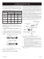
CONVERSION KITS
Model Number Description Used On
DV1350 Propane to Natural DVC35IPXLP-1
DV1348 Natural to Propane DVC35IPXNAT-1
DV1346 Propane to Natural DVC35SPPXLP-1
DV1344 Natural to Propane DVC35SPPXNAT-1
37402-5-0620 Page 7
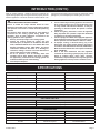
SPECIFICATIONS
Model DVC-35SPP DVC-35IP
Input BTU/HR 35,000 35,000
Height 72 1/2” 72 1/2”
Width 14 1/8” 14 1/8”
Depth 10 3/8” 10 3/8”
Gas Inlet 1/2” Pipe 1/2” Pipe
CFM 275 275
Accessories
SOR-1 Register, Side Outlet
SOK-1 Side Outlet Kit, 10” (25.4cm) Boot Assembly with Register
VINYL SIDING VENT KITS
Model Number Description
*DV-822 Vinyl Siding Vent Kit
VSK2 Vinyl Siding Vent Kit
INTRODUCTION (CONT’D)
When an existing Category 1 heater is removed or replaced, the
original venting system may no longer be sized to properly vent the
attached appliances. Instructions shall also indicate effects of an
improperly sized venting system (formation of condensate, leakage,
spillage, etc.) and shall specify the following test procedure:
WARNING
CARBON MONOXIDE POISONING HAZARD
Failure to follow the steps outlined below for each
appliance connected to the venting system being placed
into operation could result in carbon monoxide poisoning
or death.
The following steps shall be followed for each appliance
connected to the venting system being placed into
operation, while all other appliances connected to the
venting system are not in operation:
1. Seal any unused openings in the venting system.
2. Inspect the venting system for proper size and
horizontal pitch, as required in the National Fuel Gas
Code, ANSI Z223.1/NFPA 54 or the Natural Gas and
Propane Installation Code, CSA B149.1 and these
instructions. Determine that there is no blockage or
restriction, leakage, corrosion and other deciencies
which could cause an unsafe condition.
3. As far as practical, close all building doors and
windows and all doors between the space in which
the appliance(s) connected to the venting system are
located and other spaces of the building.
4. Close replace dampers.
5. Turn on clothes dryers and any appliance not connected
to the venting system. Turn on any exhaust fans, such
as range hoods and bathroom exhausts, so they are
operating at maximum speed. Do operate a summer
exhaust fan.
6. Follow the lighting instructions. Place the appliance
being inspected into operation. Adjust the thermostat
so appliance is operating continuously.
7. Test for spillage from draft hood equipped appliances
at the draft hood relief opening after 5 minutes of main
burner operation. Use the ame of a match or candle.
8. If improper venting is observed during any of the
above tests, the venting system must be corrected in
accordance with National Fuel Gas Code, ANSI Z223.1/
NFPA 54 and/or Natural Gas and Propane Installation
Code, CSA B149.1.
9. After is has been determined that each appliance
connected
to the venting system properly vents when
tested as outlined above, return doors, windows,
exhaust fans, replace dampers and any other gas-red
burning appliance to their previous conditions of use.

37402-5-0620Page 8
GAS SUPPLY
Locating Gas Supply
The gas line can enter the unit either through the oor or outside
wall. The gas line opening should be made at this time. Location
of the opening will be determined by the position of oor joists and
the valve and union used for servicing.
RECOMMENDED GAS PIPE DIAMETER
Pipe
Length
Schedule 40 Pipe
Inside Diameter
Tubing, Type L
Outside Diameter
Natural Propane Natural Propane
0-10 feet
0-3 meters
1/2”
12.7 mm
3/8”
9.5mm
1/2”
12.7 mm
3/8”
9.5 mm
10-40 feet
4-12 meters
1/2”
12.7 mm
1/2”
12.7mm
5/8”
15.9 mm
1/2”
12.7 mm
40-100 feet
13-30 meters
1/2”
12.7 mm
1/2”
12.7mm
3/4”
19 mm
1/2”
12.7 mm
100-150 feet
31-46 meters
3/4”
19 mm
1/2”
12.7 mm
7/8”
22.2 mm
3/4”
19 mm
NOTE: Never Use plastic pipe. Check to conrm whether your lo-
cal codes allow copper tubing or galvanized.
NOTE: Since some municipalities have additional local codes, it
is always best to consult your local authority and installation code.
The use of the following gas connectors is recommended:
– ANS Z21.24 Appliance Connectors of Corrugated Metal Tubing
and Fittings
– ANS Z21.45 Assembled Flexible Appliance Connectors of
Other Than All-Metal Construction
The above connectors may be used if acceptable by the author-
ity having jurisdiction. The Commonwealth of Massachusetts re-
quires that a exible appliance connector cannot exceed three feet
in length.
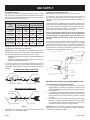
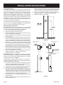
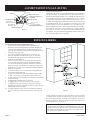
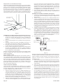
FLEXIBLE GAS LINE CONNECTION
GAS SUPPLY
TEE HANDLE
FLEX TUBING
NPT NIPPLE
FLARE SHUT OFF VALVE
FLARE FITTING
RIGID GAS LINE CONNECTION
CLOSE NIPPLE
TEE HANDLE
NPT NIPPLE
NPT UNION
SHUT OFF VALVE
NPT GAS SUPPLY
Figure 1
Consult the current National Fuel Gas Code, ANSI Z223.1 CAN/
CGA-B149 (.1 or .2) installation code.
Installing a New Main Gas Shut-Off
Each appliance should have its own manual gas shut-off.
A manual main gas shut-off should be located in the vicinity of
the unit. Where none exists, or where its size or location is not
adequate, contact your local authorized installer for installation or
relocation.
Compounds used on threaded joints of gas piping shall be resis-
tant to the action of liqueed petroleum gases. The gas lines must
be checked for leaks by the installer. This should be done with a
soap solution watching for bubbles on all exposed connections,
and if unexposed, a pressure test should be made.
Never use and exposed ame to check for leaks. Appliance
must be disconnected from piping at inlet of control valve
and pipe capped or plugged for pressure test. Never pres-
sure test with appliance connected; control valve will sustain
damage!
A gas valve and ground joint union should be installed in the gas
line upstream of the gas control to aid in servicing. It is required
by the National Fuel Gas Code that a drip line be installed near
the gas inlet. This should consist of a vertical length of pipe tee
connected into the gas line that is capped on the bottom in which
condensation and foreign particles may collect.
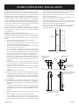
GAS SUPPLY PIPING
1/8 NPT PLUGGED HOLE
FOR TEST GAGE
GROUND JOINT UNION
3” MINIMUM
MANUAL SHUT-OFF VALVE
GAS SUPPLY
INLET
1/8 NPT PLUGGED HOLE
FOR TEST GAGE
GAS
VALVE
Figure 2
METHOD OF INSTALLING A TEE FITTING SEDIMENT TRAP
Pressure Testing of the Gas Supply System
1. To check the inlet pressure to the gas valve, a 1/8” N.P.T.
plugged tapping, accessible for test gauge connection, must
be placed immediately upstream of the gas supply connection
to the appliance.
2. The appliance and its individual shut-off valve must be discon-
nected from the gas supply piping system during any pressure
testing of that system at test pressures in excess of 1/2 psig
(3.5 kPa).
3. The appliance must be isolated from the gas supply piping
system by closing its individual manual shut-off valve during
any pressure testing of the gas supply piping system at test
pressures equal to or less than 1/2 psig (3.5 kPA)
Attention! If one of the above procedures results in pressures in
excess of 1/2 psig (14” w.c) (3.5 kPa) on the appliance gas valve,
it will result in a hazardous condition.

37402-5-0620 Page 9
TOP VIEW OF VALVE
PRESSURE REGULATOR
OUTLET PRESSURE TA
P
GAS OUTLET
PILOT GAS OUTLET
PILOT ADJUSTMENT
SCREW BENEATH
COVER SCREW
MANUAL GAS COCK KNOB
RED RESET BUTTON
INLET
PRESSURE TAP
GAS INLET
WRENCH BOSS
VENT
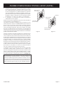
Checking Manifold Pressure
Both Propane and Natural Gas valves have a built-in pressure reg-
ulator in the gas valve. Natural Gas models will have a manifold
pressure of approximately 4.0” w.c. (.996kPa) at the valve outlet
with the inlet pressure to the valve from a minimum of 5.0” w.c.
(1.245kPa) for the purpose of input adjustment to a maximum of
7.0” w.c. (1.743kPa). Propane Gas models will have a manifold
pressure approximately 10.0” w.c. (2.49kPa) at the valve outlet
with the inlet pressure to the valve from a minimum of 11.0” w.c.
(2.739kPa) for the purpose of input adjustment to a maximum of
13.0” w.c. (3.237kPa).
A 1/8” N.P.T. plugged tapping, accessible for test gauge connec-
tion, is located on the outlet side of the gas control.
The built-in regulator comes on at approximately 1/4th pressure
and full on in 10 seconds.
Figure 3
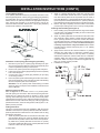
CLEARANCES
Pressure Testing Of The Gas Supply System
1. In selecting a location for installation, it is necessary to provide
adequate accessibility clearances for servicing and proper in-
stallation. A front clearance of 36” (91.4cm) is recommended.
Do not block outlet or inlet air openings on the front grill.
2. The DVC-35 minimum wall depth is 3/4” (19mm) and maximum
wall depth is 10” (254mm). The use of tubes not supplied by
the manufacturer results in unsatisfactory performance.
3. The DVC-35 can be attached to the wall or recessed into
the wall up to 9 1/2” (241mm) in depth but the minimum 3/4”
(19mm) vent/air intake system wall depth must be maintained.
Example: If furnace is recessed into the wall at a depth of 9 1/2”
(241mm), the minimum wall depth must be 10 1/4” (260mm).
4. The wall in which the furnace is recessed has (0) zero clear-
ance to the furnace sides and top.
5. When using side discharge registers, SOR-1 or SOK-1, the
furnace cannot be recessed into the wall.
6. Clearance to sidewall or combustible material is 4” (102mm).
7. Ceiling clearance is 4” (201mm).
8. Floor and rear wall clearance is (0) zero inches.
9. Clearance of 18” (457mm) is required to sidewall or combus-
tible material when ush mounted SOR-1, side outlet register
is used.
10. The minimum distance from the center of the vent cap to the
nearest outside corner or obstruction is 12” (305mm).
Figure 4
The vent terminal of this direct vent appliance shall be located
at least 9” (229mm) from any opening through which ue gases
could enter a building. The bottom of the vent terminal and the air
intake shall be located at least 12” (305mm) above grade. See
vent location, Figure 4.
WARNING
The nearest point of the vent cap should be a minimum
horizontal distance of six (6) feet (1.83m) from any pressure
regulator. In case of regulator malfunction, the six (6) feet
(1.83m) distance will reduce the chance of gas entering the
vent cap.
GAS SUPPLY (CONT’D)

37402-5-0620Page 10
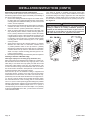
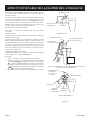
INSTALLATION INSTRUCTIONS
Locating Wall Opening
The furnace is to be located on an outside wall. Locate wall studs
so that wall opening will be located between wall studs. The fur-
naces is 14 1/8” (358mm) in width and can be recessed between
standard 16” (406mm) on center wall stud. The wall opening re-
quired as shown in Figure 5 is a diameter of 7 1/2” (191mm).
Locate and cut wall opening. If there is insulation above the wall
opening (air inlet tube) a barrier should be installed above the wall
opening (air inlet tube) to prevent insulation from coming in con-
tact with the air inlet tube. The barrier must not penetrate into the
7-1/2” (191mm) diameter wall opening.
A template is provided in furnace carton for positioning furnace on
the wall. Also, refer to Figure 5 and Figure 7 for positioning the
furnace on wall and for locating gas line connection.
Installing Optional Side Outlets
Side outlet register, SOR-1 may be installed on one or both sides
of the furnace at the required clearances of 18” (457mm) to adja-
cent wall or combustible material as shown in Figure 6.
1. Turn “OFF” all electric power to the furnace.
2. Remove the front panel from the furnace.
3. Remove the (2) #8 X 3/8” (9mm) screws that attach the inner
shield cover plate to the inner shield.
4. Scribe a line between the four dimples on the outer casing side
to form a square.
5. Drill a pilot hole within the scribed square on the outer casing.
Remove the sheet metal within the scribed square with a tin
snips or comparable tool. Attention! Do not cut the electrical
wires located between the outer casing and the inner shield.
6. Insert the 5” x 5” (127mm x 127mm) inner boot through the
outer casing. Align the clearance holes on the inner boot with
the crew holes on the inner shield. Attach inner boot to inner
shield with (2) #8 x 3/8” (9mm) screws removed in Step 3.
7. Place the register over the 5 1/2” (140mm) square opening with
the louvers set for the desired direction and mark the mounting
holes using the register as a template.
8. Drill (2) 1/8” diameter holes in cabinet side and attach the
register with (2) #10 x 1” (25mm) provided screws.
9. Installation of SOR-1 is completed.
Side outlet kit, SOK-1, 10” (254mm) boot assembly with register,
for warm air discharge into an adjoining room may be installed on
either side of the furnace at the required clearance of 4” (102mm)
to adjacent wall as shown in Figure 6.
To install SOK-1, please use step 1 through 5 in the SOR-1 in-
structions for DVC-35 furnaces. Then, use the following Steps to
complete the installation of the SOK-1.
1. Using the inner and outer boots as hole templates, mark and
drill (4) 1/8” (3mm) diameter holes in the inner shield and (4)
1/8” (3mm) diameter holes in the cabinet side.
2. Locate and cut a 6 3/4” (171mm) square opening through wall.
3. Attach furnace to wall (see Attaching Furnace to Wall).
4. With furnace in place, after checking alignment of side outlet
opening in wall and furnace, place the 9 3/8” x 9 3/8” (238mm
x (238mm) side outlet wall plate over outer boot, pass the outer
boot through the wall and attach side wall plate to furnace side
of wall with (2) #10 x 1 1/2” (38mm) provided screws.
5. Attach outer boot to the cabinet side with (4) #8 x 1/4” (6mm)
provided screws.
6. Position and attach inner boot to inner shield with (4) #8 x 1/4”
(6mm) provided screws.
7. Place the register over the 6 3/4” (171mm) square opening with
the louvers positioned for the desired discharge direction and
mark the mounting holes using the register as a template.
8. Drill (2) 1/8” (3mm) diameter holes in the wall and attach the
register with (2) #10 x 1 1/2” (38mm) provided screws.
9. Installation of SOK-1 is completed.
Figure 5
4”
MINIMUM TO COMBUSTIBLE
W
ALL OR SURFACE
VENT
TERMINA
L
4” MINIMUM TO COMBUSTIBLE
WALL OR SURFACE
18”MIN. CLEARANCE TO
WALL OR COMBUSTIBLE
SURFACE USING
MODEL
SOR-1 SIDE REGISTER
5½”
5½”
12”
CLEARANCE FOR SIDE OUTLET KITS TO ADJACENT W
ALL
UNIT CANNOT BE RECESSED
WHEN SIDE REGISTERS ARE
USED.
WHEN SIDE REGISTERS ARE
NOT USED, UNIT MAYBE RECESSED
UP TO 9 1/2”
Figure 6

37402-5-0620 Page 11
Locating Electric Supply
A 7/8” (22mm) diameter knockout is provided at the bottom of the
left and right side panels. A three-prong (grounding) plug assembly
is located within the control compartment (bottom) of the furnace.
Please remove 7/8” (22mm) knockout from appropriate side panel
when routing plug assembly to an electrical outlet. Unit can be
hard wired when recessed. Remove the 3 prong plug assembly
and terminate inside the unit junction box.
Figure 7
Installation of Three-prong (Grounding) Plug Assembly
1. Disconnect nylon cap on 3’ (92cm) plug assembly from nylon
plug on wiring harness. Remove 3’ (92cm) plug assembly from
control compartment (bottom) of the furnace.
2. Remove 7/8” (22mm) knockout from appropriate side panel.
3. Insert nylon cap on 3’ (92cm) plug assembly into the 7/8” (22mm)
hole in the side panel.
4. Connect nylon cap on 3’ (92cm) plug assembly to nylon plug
on the wiring harness.
5. Place 7/8” (22mm) strain relief bushing around the cord of the 3’
(92cm) plug assembly. Insert 7/8” (22mm) strain relief bushing
into the 7/8” (22mm) hole in the side panel.
Attention! The 7/8” (22mm) strain relief bushing is located
within the same envelope as the Installation Instructions and
Owner’s Manual.
Attaching Furnace to Wall
Refer to Figure 5 for the location of the 7 1/2” (191mm) diam-
eter wall opening for the furnace. After the wall opening has been
located and cut, position ue outlet on furnace in center of wall
opening. When attaching furnace to the wall, remove that portion
of baseboard and molding on the wall which is behind the furnace.
Attach furnace to wall, at the outer casing top, with (2) toggle bolts
provided and to oor, at the out casing bottom, with (2) #10 x 1 1/2”
(38mm) screws provided.
Cutting Vent Tubes
This is the most important part of the installation. With the furnace
installed on the wall, the 6” (152mm) diameter inlet tube and the 4”
(102mm) diameter ue outlet tube are to be marked and cut using
the following procedure.
1. Attach 6” (152mm) diameter air inlet tube onto the collar of air
drop assembly. Be sure 6” (152mm) diameter air inlet tube is
placed as far as possible onto the collar of the air drop assem-
bly. Mark the 6” (152mm) diameter air inlet tube 1/2” (13mm)
beyond the outside wall. Remove 6” (152mm) diameter air inlet
tube from collar of air drop assembly.
2. Attach 4” (102mm) diameter ue outlet tube onto ue outlet
collar on combustion chamber. Be sure 4” (102mm) diameter
ue outlet tube is placed as far as possible onto the collar of
ue outlet. Mark the 4” (102mm) diameter ue outlet tube 2 1/4”
(57mm beyond the outside wall. Remove 4” (102mm) diameter
ue outlet tube from collar of ue outlet on combustion chamber.
3.
Mark or wrap tape completely around the tubes at the marked
points to help in making a true cut. Do not crimp or enlarge tubes.
Installing Vent Assembly (See Figure 8)
1. Place caulking (not provided) beneath the edge of the outside
mounting plate. Use additional caulking to correct uneven wall
surface, such as clapboard.
2. Attach 6” (152mm) diameter air inlet tube onto the collar of air
drop assembly. Attach caulked, outside mounting plate into
the 6” (152mm) diameter air inlet tube. Position the outside
mounting plate so that 6” (152mm) diameter air inlet tube has a
slight downward slope to the outside. The downward slope is
necessary to prevent the entry of rainwater. Attach outside
mounting plate to exterior wall with (4) #10 x 1 1/2” (38mm)
screws provided.
3. Apply furnace cement or RTV silicone sealant to 4” (102mm)
diameter ue outlet collar on combustion chamber and to
4” (102mm) diameter collar on vent cap. Attach 4” (102mm)
diameter ue outlet tube onto ue outlet collar on combustion
chamber. Attach vent cap into the 4” (102mm) diameter ue
outlet tube. Attach vent cap to outside mounting plate with (3)
#10 x 1/2” (13mm) screws provided.
4. Installation is complete.
Figure 8
INSTALLATION INSTRUCTIONS (CONT’D)

37402-5-0620Page 12
Reassembly and Resealing Vent-Air Intake System
When vent-air intake system is removed for servicing the furnace,
the following steps will assure proper reassembly and resealing of
the vent-air intake assembly.
1. Remove old caulking beneath the edge of the outside mount-
ing plate. Apply new caulking beneath the edge of the outside
mounting plate. Use additional caulking to correct uneven wall
surface, such as clapboard.
2. Remove old furnace sealant from ue outlet collar on combustion
chamber and collar of vent cap. Remove old furnace sealant
from both ends of 4” (102mm) diameter ue outlet tube.
3. Attach 6” (152mm) diameter air inlet tube onto the collar of air
drop assembly. Attach caulked, outside mounting plate into
the 6” (152mm) diameter air inlet tube. Position the outside
mounting plate so that 6” (152mm) diameter air inlet tube has
a slight downward slope to the outside. The downward slope
is necessary to prevent the entry of rainwater. Attach outside
mounting plate to exterior wall with (4) #10 x 1 1/2” (38mm)
screws provided.
4. Apply furnace cement or RTV silicone sealant to 4” (102mm)
diameter ue outlet collar on combustion chamber and to
4” (102mm) diameter collar on vent cap. Attach 4” (102mm)
diameter ue outlet tube onto ue outlet collar on combustion
chamber. Attach vent cap into the 4” diameter ue outlet tube.
Attach vent cap to outside mounting plate with (3) #10 x 1/2”
(13mm) screws provided.
5. Reassembly and resealing vent-air intake system is completed.
Installing a Vent Near a Window Ledge,
Other Type of project or on Siding (vinyl, aluminum, etc.)
Direct vent furnaces are designed to be installed on a uniform out-
side wall. When the wind comes from any angle (up, down, or from
either side), it must hit the vent cap equally over both the air inlet
and the ue outlet portions of the vent. Any wall projection, such
as a door or window casing, which disturbs the wind on one side of
the air inlet section will result in back pressure on the ue section
smothering the ame and eventual pilot outage.
When the vent cap is to be installed on siding or it appears that
a projection within 6” (152mm) of any side of the air inlet section
could shield the air inlet section, the entire vent should be sup-
ported away from the wall at least the distance of the projection. 2”
x 4” (51mm x 102mm) framing whose outside dimensions match
the overall dimensions of the mounting plate is recommended.
The 2” x 4” (51mm x 102mm) framing protects siding from possible
warpage or discoloration. All joints can then be sealed and painted.
The wall depth plus the additional depth of the 2” x 4” (51mm x
102mm) framing should not exceed a total depth of 10” (254mm)
for DVC-35. See Figure 9. If it does, you will need to use the DV-
1190 Extended Flue Kit.
INSTALLATION INSTRUCTIONS (CONT’D)
Vinyl siding kit, DV-822, is available from Empire Comfort Sys-
tems, Inc. The depth is 3” (76mm), which enables the vent cap to
be extended away from siding or projections. The wall depth plus
the additional 3” (76mm) depth of the vinyl siding vent cap exten-
sion should not exceed a total depth of 10” (254mm) for DVC-35.
See Figure 10.
Figure 9 Figure 10
WARNING
When vinyl siding vent kit, DV-822 or 2” x 4” (51mm x 102mm)
framing is added to an existing installation (furnace is
installed) do not attempt to add sections of pipe to the ue
outlet tube or air inlet tube. An air tight seal is required for
both tubes. Refer to Parts List, page 20 to order tubes.

37402-5-0620 Page 13
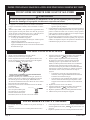
DVC-35SPP STANDING PILOT LIGHTING INSTRUCTIONS
FOR YOUR SAFETY READ BEFORE LIGHTING
A. This appliance has a pilot which must be lighted by hand.
When lighting the pilot, follow these instructions exactly.
B. BEFORE LIGHTING smell all around the appliance area
for gas. Be sure to smell next to the oor because some
gas is heavier than air and will settle on the oor.
WHAT TO DO IF YOU SMELL GAS
• Do not try to light any appliance.
• Do not touch any electrical switch; do not use any
phone in your building.
• Immediately call your gas supplier from a
neighbor’s phone, Follow the gas supplier’s
instructions.
• If you cannot reach your gas supplier, call the re
department.
C. Use only your hand to push in or turn the gas control
knob. Never use tools. If the knob will not push in or
turn by hand, don’t try to repair it; call a qualied service
technician. Force or attempted repair may result in a re
or explosion.
D. Do not use this appliance if any part has been under water.
Immediately call a qualied service technician to inspect
the appliance and to replace any part of the control system
and any gas control which has been under water.
LIGHTING INSTRUCTIONS
1. STOP! Read safety information above.
2. Turn off all electric power to the appliance.
3. Remove control access panel (lower front panel).
4. Turn gas control knob clockwise
to “OFF.”
5. Wait ten (10) minutes to clear out any gas. Then smell
for gas, including near the oor. If you smell gas, STOP!
Follow “B” in the safety information above. If you don’t
smell gas, go to the next step.
6. Remove the pilot access cover located on the combustion
chamber.
7. Find pilot - follow metal
tube from gas control.
The pilot is located
between the two burner
tubes behind the pilot
access cover.
8. Turn gas control knob counterclockwise
to
“Pilot.”
9. Push and hold red reset button down completely and
repeatedly push the ignitor button until the pilot burner
is lit. Pilot may also be lit with a match. Continue to hold
the red rest button down for about one (1) minute after
the pilot is lit. Release button and it will pop back up. Pilot
should remain lit. If it goes out, repeat step 4 through 9.
• If button does not pup up when released, stop and
immediately call a qualied service technician or gas
supplier.
• If the pilot will not stay lit after several tries, turn
the gas control knob to “OFF” and call your service
technician or gas supplier.
10. Replace pilot access cover.
11. Turn gas control knob counterclockwise
to
“ON.”
12. Replace control access panel (lower front panel).
13. Turn on all electric power to the appliance.
GA
SCONTROL KNOBSHOWN IN “OFF”POSITION
THERMOCOUPLE
PILOT BURNER
TO TURN OFF GAS TO APPLIANCE
1. Turn off all electric power to appliance if service is to be
performed.
2. Remove control access panel (lower front panel).
3. Push in gas control knob slightly and turn
clockwise to “OFF.” Do not force.
4. Replace control access panel (lower front panel).
WARNING
If you do not follow these instructions exactly, a re or explosion may result causing property damage,
personal injury or loss of life.

37402-5-0620Page 14
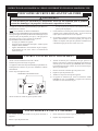
DVC-35IP INTERMITTENT PILOT LIGHTING INSTRUCTIONS
FOR YOUR SAFETY READ BEFORE LIGHTING
A. This appliance is equipped with an ignition device which
automatically lights the pilot. Do NOT try to light the pilot
by hand.
B. BEFORE LIGHTING smell all around the appliance area
for gas. Be sure to smell next to the oor because some
gas is heavier than air and will settle on the oor.
WHAT TO DO IF YOU SMELL GAS
• Do not try to light any appliance.
• Do not touch any electrical switch;
do not use any phone in your building.
• Immediately call your gas supplier from a neighbor’s
phone, Follow the gas supplier’s instructions.
• If you cannot reach your gas supplier, call the re
department.
C. Use only your hand to push in or turn the gas control
knob. Never use tools. If the knob will not push in or
turn by hand, don’t try to repair it; call a qualied service
technician. Force or attempted repair may result in a re
or explosion.
D. Do not use this appliance if any part has been under
water. Immediately call a qualied service technician
to inspect the appliance and to replace any part of the
control system and any gas control which has been under
water.
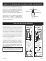
OPERATING INSTRUCTIONS
1. STOP! Read safety information above.
2. Turn off all electric power to the appliance.
3. This appliance is equipped with an ignition device which
automatically lights the pilot. Do not try to light the pilot
by hand.
HONEYWELL IP SMART VALVE
4. Remove front panel door.
5. Slide gas control switch to “OFF.”
6. Wait ten (10) minutes to clear out any gas. Then smell
for gas, including near the oor. If you smell gas, STOP!
Follow “B” in the safety information above. If you don’t
smell gas, go to the next step.
7. Slide gas control switch to “ON.”
8. Replace front panel door.
9. Turn on all electric power to the appliance.
10. If the appliance will not operate, follow the instructions,
“TO TURN OFF GAS TO APPLIANCE” and call your
service technician or gas supplier.
IGNITOR
CONTROL
OFF
ON
GAS FLOW
GAS VALVE SHOWNIN OFF POSITION
TO TURN OFF GAS TO APPLIANCE
1. Turn off all electric power to the appliance if service is
to be performed.
2. Remove front panel door.
3. Slide gas control switch to “OFF.”
4. Replace front panel door.
WARNING
If you do not follow these instructions exactly, a re or explosion may result causing property damage,
personal injury or loss of life.

37402-5-0620 Page 15
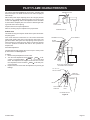
PILOT FLAME CHARACTERISTICS
The correct pilot ame (Figure 11) will be blue, extending past
the thermocouple. The ame will surround the thermocouple just
below the tip.
Natural Gas pilots require adjusting when the inlet gas pressure
is above 5” w.c. (1.245kPa). Remove the pilot cover screw on the
control valve (Figure 3), and turn the adjustment screw clockwise
to reduce ame. Replace pilot cover screw to eliminate gas leak-
ing at that control valve opening.
Propane Gas will not require adjustment.
After use, cleaning may be required for the proper ame.
IP-Model Pilot
This heater is using a Honeywell “Smart Valve” system for intermit-
tent pilot ignition.
On a call for heat, this control turns on a 24 volt mini hot surface
ignitor which lights a pilot that in turn lights the main burner. The
gas valve used in this system is a step opening which opens at a
lower pressure for ignition and then steps to a full inlet pressure
of 4” W.C. pressure on Natural Gas and 10” W.C. pressure on
Propane Gas.
Pilot Flame Adjustment
The pilot ame should envelop 3/8 to 1/2 inch (10 to 13mm) of the
tip of the ame rod. See Figure 11.
To adjust:
1. Remove the pilot adjustment cover screw.
2. Turn the inner adjustment screw clockwise
to de-
crease or counterclockwise to increase pilot
ame. Pilot adjustment is shipped at full ow rate. Turn the
inner adjustment screw clockwise
if the inlet pres-
sure is too high.
3. Replace the cover screw after the adjustment to prevent gas
leakage.
THERMOCOUPLE
BURNER
SPARK
ELECTRODE
PILOT
STANDING PILOT
THERMOCOUPLE
PILOT SHIELD
SPARK
ELECTRODE
PILOT LOCATION END VIEW
STANDING PILOT SHOWN
3/8”TO 1/2”
PILOT FLAME
GROUND
ELECTRODE
BURNER
PILOT
HOT SURFACE
IGNITOR
FLAME
ROD
IP-MODEL PILOT
Figure 11

37402-5-0620Page 16
MAIN BURNER FLAME CHARACTERISTICS
The correct ame will be a short, blue inner ame with a much
larger, light blue, outer ame. The burner does not have a primary
air adjustment. The ame will be correct if the factory-set pressure
and orice opening are used. After the furnace has been operating,
the burner ports may be blocked by foreign matter carried in by
combustion air. Therefore, cleaning of the burner may be needed
for proper ame.
The clean burner port disconnect the gas supply to the valve, and
remove the screws fastening the burner. After removing the burner
door from the burner box, remove each main burner. Pilot mount-
ing bracket will need to be unscrewed and moved out the way to
remove all burners. Burners can be blown out using compressed
air or by blowing through them. Be sure there is no lint or foreign
debris blocking the burner ports. Reassemble using the same
screws earlier removed and locate pilot in the same position as
before and noted above.
Figure 12
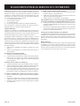
WIRING
The appliance, when installed, must be electrically grounded in
accordance with local codes or, in the absence of local codes, with
the National Electrical Code, ANSI/NFPA 70 or Canadian Electrical
Code, CSA C22.1, if an external electrical source is utilized. This
appliance is equipped with three-prong (grounding) plug for
your protection against shock hazard and should be plugged
directly into a properly grounded three-prong receptacle. Do
not cut or remove the grounding prong from this plug. For an
ungrounded receptacle, an adapter, which has two prongs and a
wire for grounding, can be purchased, plugged into the ungrounded
receptacle and its wire connected to the receptacle mounting screw.
With this wire completing the ground, the appliance cord plug can be
plugged into the adapter and be electrically grounded. A 7/8” hole
is provided in the junction box for use with a conduit connector if
local codes require this type of protection.
Installing the ON/OFF Device
To install an ON/OFF device (such as a wall switch, remote, toggle
switch, or thermostat), remove the wire nut from the two wires from
the valve. Run additional wire from the valve wires to the ON/OFF
device. Install the ON/OFF device in the same room as the furnace
following the installation instructions supplied with it. In the absence
of instructions, install the ON/OFF device 4 to 5 feet above the oor
on an interior wall not affected by another heating source (i.e. stove
or water heater) or the temperature of an adjoining room.
CAUTION
Label all wires prior to disconnection when servicing controls.
Wiring errors can cause improper and dangerous operation.
Verify proper operation after servicing.
To Conserve Gas: Turn off pilot when heater is not in use.
Figure 13
LIMIT CONTROL
——— — ——————————————— —
CONTRÔLE
LIMITE
TRANSFORMER
——— —— —————————————————— —
TRANSFORMATEUR
SPT-3 CORDSET
——— —— ——————————————— —
CORDON SPT-3
WHITE (BLANC)
BLACK (NOIR)
MOTOR
————— —————
MOTEUR
WIRING DIAGRAM
————————————————————
CÂBLAGE DE DIAGRAMME
YELLOW (JAUNE)
AUTO FAN
——— —— ——————————— —
VENTILATEUR
AUTO
IF ANY OF THE ORIGINAL WIRE AS SUPPLIED
WITH THIS UNIT MUST BE REPLACED, IT MUST
BE REPLACED WITH 150°C THERMOPLASTIC
4/64 THICK OR ITS EQUIVALENT.
120V. 60Hz. LESS THAN 3 AMPS
S´IL YAUN FIL ORIGINAL FOURNI AVEC
L´APPAREIL QUI DOIT ÊTRE REMPLACÉ. IL DOIT
ÊTRE REMPLACÉ AVEC UN ÉQUIVALENT À FIL
4/64” THERMOPLASTIQUE 150°C.
120V. 60Hz. MOINS DE 3 AMPS.
—————— ———————————————————————————————————————————————
RED/WHT (ROUGE/BLANC)
RED (ROUGE)
LADDER WIRING DIAGRAM
——————————————————————————
ÉCHELLE ÉLECTRIQUE
SCHÉMATIQUE
RED/WHT
ROUGE/BLANC
TRANSFORMER
——— —— —————————————————— —
TRANSFORMATEUR
24 VOLTS
120 VOLTS
RED/WHT
ROUGE/BLANC
BLACK
NOIR
RED/WHT
ROUGE/BLANC
LOW VOLTAGE (BAS VOLTAGE)
120 VOLTS
JUNCTION BOX
—— —— ——— —————————————— ——
BOÎTE DE JONCTION
RED/WHT
ROUGE/BLANC
LIMIT SWITCH
——— — ——————————————— —
CONTRÔLE DE
TOLÉRANCE
BLK (NOIR)
GRN (VERT)
WHT (BLANC)
BLK (NOIR)
BLK (NOIR)
BLK (NOIR)
IP UNITS
YELLOW
JAUNE
WHITE
BLANC
BLACK
NOIR
MOTOR
————— —————
MOTEUR
AUTO FAN
——— —— ——————————— —
VENTILATEUR
AUTO
ON/OFF DEVICE
——— — ——————————————— —
ON/OFF
PÉRIPHÉRIQUES
ON/OFF DEVICE
——— — ——————————————— —
ON/OFF
PÉRIPHÉRIQUES
ON/OFF DEVICE
——— — ——————————————— —
ON/OFF
PÉRIPHÉRIQUES
WIRE NUT / ON/OFF DEVICE
——— — —————————————————————————————— —
FILS TORSADÉS / ON/OFF
PÉRIPHÉRIQUES
WIRE NUT
——— — ——————————————— —
FILS TORSADÉS
TRANSFORMER
——— —— —————————————————— —
TRANSFORMATEUR
SPT-3 CORDSET
——— —— ——————————————— —
CORDON SPT-3
WHITE (BLANC)
BLACK (NOIR)
MOTOR
————— —————
MOTEUR
YELLOW (JAUNE)
RED/WHT (ROUGE/BLANC)
YELLOW
JAUNE
WHITE
BLANC
BLACK
NOIR
RED/WHT
ROUGE/BLANC
TRANSFORMER
——— —— —————————————————— —
TRANSFORMATEUR
24 VOLTS
MOTOR
————— —————
MOTEUR
AUTO FAN
——— —— ——————————— —
VENTILATEUR
AUTO
120 VOLTS
BLACK
NOIR
RED/WHT
ROUGE/BLANC
LOW VOLTAGE (BAS VOLTAGE)
120 VOLTS
JUNCTION BOX
—— —— ——— —————————————— ——
BOÎTE DE JONCTION
RED/WHT
ROUGE/BLANC
GAS VALV E
——— —— ————————————— —
VALVE DE GAZ
BLACK (NOIR)
RED/WHT (ROUGE/BLANC)
RED/WHT (ROUGE/BLANC)
LIMIT CONTROL
——— — ——————————————— —
CONTRÔLE
LIMITE
WIRING DIAGRAM
————————————————————
CÂBLAGE DE DIAGRAMME
AUTO FAN
——— —— ——————————— —
VENTILATEUR
AUTO
IF ANY OF THE ORIGINAL WIRE AS SUPPLIED
WITH THIS UNIT MUST BE REPLACED, IT MUST
BE REPLACED WITH 150°C THERMOPLASTIC
4/64 THICK OR ITS EQUIVALENT.
120V. 60Hz. LESS THAN 3 AMPS
S´IL YAUN FIL ORIGINAL FOURNI AVEC
L´APPAREIL QUI DOIT ÊTRE REMPLACÉ. IL DOIT
ÊTRE REMPLACÉ AVEC UN ÉQUIVALENT À FIL
4/64” THERMOPLASTIQUE 150°C.
120V. 60Hz. MOINS DE 3 AMPS.
—————— ———————————————————————————————————————————————
LADDER WIRING DIAGRAM
——————————————————————————
ÉCHELLE ÉLECTRIQUE
SCHÉMATIQUE
BLK (NOIR)
GRN (VERT)
WHT (BLANC)
SPP UNITS
GAS VALV E
——— —— ————————————— —
VALVE DE GAZ
LIMIT CONTROL
——— — ——————————————— —
CONTROL DE
TOLERANCE
BLACK
NOIR
ON/OFF DEVICE
——— — ——————————————— —
ON/OFF
PÉRIPHÉRIQUES
WIRE NUT
—————————————---------------- —
FILS TORSADÉS
ON/OFF DEVICE
——— — ——————————————— —
ON/OFF
PÉRIPHÉRIQUES
WIRE NUT
—————————————---------------- —
FILS TORSADÉS

37402-5-0620 Page 17
SERVICE AND MAINTENANCE SUGGESTIONS
GENERAL: All furnaces have been re-tested to check for proper
operation. This includes, main burner ame, pilot ame, fan op-
eration, fan control, limit control and automatic valve operation. If
the furnace fails to function on initial installation, it is advisable to
re-check the following:
1. 115 volts to the junction box.
2. Inlet gas pressure.
3. The 24 volt system.
4. Type of gas being used and that shown on the rating label.
Standing Pilot Model
Servicing the Pilot and Main Burners, Pilot Orice, Thermo-
couple, and Main Burner Orices: Disconnect the gas supply at
the inlet to the control valve. Then remove the burner door to gain
access to the above listed components.
If Electrode Does Not Produce Spark:
1. Check wire connections.
2. Check gap for pilot burner to the electrode tip. Should be
between 1/8” (3mm) and 3/16” (4.8mm). Electrode wire and
tip must be more than 1/4” (6.3mm) away from all other metal
components.
If Pilot Does Not Light By Any Means:
1. Check valve knob for being in the “Pilot” position.
2. Check pilot adjustment for being full open (counterclockwise
to open).
3. If gas is available in the supply tubing, the pilot orice and/or
pilot burner is probably restricted by a spider web. Clean pilot
assembly and relight.
If Pilot Does Not Remain On After Releasing Knob:
1. Follow instructions and hold button down longer and harder.
2. Determine if pilot ame extends past thermocouple; if not, adjust
input or clean pilot burner.
3. Replace thermocouple if millivolts read less than 15 millivolts.
Pilot Outage During Normal Operation:
1.
Check air inlet tube for a good tight t at both ends (6” diameter
tube).
2. Check burner door and pilot hole cover for tight seal.
3. Check input by manifold pressure gauge or gas meter.
Main Gas Valve Does Not Open when ON/OFF Device Is
Turned To On:
1. Check for 24 volts to valve by removing one wire and touching
to the SAME TERMINAL it was on. Terminal should have a
light spark.
2. To check for line voltage to furnace, remove front panel and
short across two-terminal fan control to allow fan to operate.
Cleaning Combustion (Exchanger) Assembly
A QUALIFIED SERVICE PERSON should remove the combustion
(exchanger) assembly and ue bafes. Apply air pressure to the
inside of the combustion (exchanger) assembly and ue bafes in
order to clear all passageways.
Oiling the Motor
The Fan motor should be cleaned and oiled once each heating
season. Oil holes are located on the top at each end of the mo-
tor. Use a few drops of #10 motor oil. To clean the motor, blow
air through its ventilation openings with a vacuum cleaner or low
pressure air source.

37402-5-0620Page 18
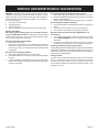
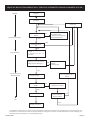
START
System Check
Trial for
Ignition
Main Burner
Operation
END
Pilot Valve Opens
Ignitor Powered
Flame Signal
Detected
Call for Heat
Ignitor OFF
Main Valve Opens
Internal Check
OK
Pilot Light and Flame is
Sensed During Trial For
Ignition (1)
Apply 24 VAC
To Appliance
Main Pilot Valves
Close
Call for Heat Ends
Flame Signal
Lost?
Pilot Valve Ignition OFF
Wait for Flame Signal to
Disappear
Pilot Valve Closes
Ignition OFF
Main Pilot
Valves Close
Flame Lost More
Than 5Times in
One Call for Heat
5 Minute Retry Delay
3 Second Flame Recycle
Delay
YES
NO
NO
YES
NO
YES
YES
NO
YES
NO
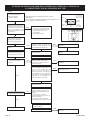
(1) Ignitor will turn OFF about 30 seconds into the trial for ignition if the pilot flame has not lit. It will turn back ON for the final 30 seconds
of the 90 second trial for ignition. The pilot valve will be energized during the entire trial for ignition. This is normal operation for this gas
ignition system.
DVC-35IP INTERMITTENT PILOT SEQUENCE OF OPERATION
(1) Ignitor will turn OFF about 30 seconds into the trial for ignition if the pilot ame has not lit. It will turn back ON for the nal 30
seconds of the 90 second trial for ignition. The pilot will be energized during the entire trial for ignition. This is normal operation
for this gas ignition system.

37402-5-0620 Page 19
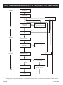
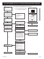
START
IP SYSTEM TROUBLESHOOTING SEQUENCE
Turn OFF Gas Supply
Disconnect System Control
Harness
Set Thermostat to Call for
Heat
Check for Proper Voltage at
Control Harness (See Inset A-
Vo ltageShouldbe 24V
Between Thermostat and 24V
Common, and 24V Between
24V Common and 24V Hot.)
Plug Harness into SmartValve
Control
Wait for Internal Check Delay
(SV9501)
Igniter Warms UP and Glows
Red
Note: Igniter Will Cycle OFF
and Back ON Once During the
90 Second Ignition Trial
Turn On Gas Supply
Pilot Burner Lights
Main Valve Opens and
Main Burner Lights
System is Okay
Check
Line Voltage Power
Low Voltage Transformer
Limit Controller
Thermostat
Wiring
Unplug Pilot Burner Cable.
Measure Voltage at SmartValue HSI
Element Output (See Inset B) 24V
Nominal
Replace Igniter/Flame Rod
Assembly
Reconnect Pilot Burner Cable
Check that Pilot Gas is Flowing
Wait to Assure Pilot Gas Tubing is
Purged.
Measure Voltage Between 24V Hot
and 24V Common Leads to
SmartValve Control. Must Measure
at Least 19.5 VA C with Igniter
Powered. See InsetAto Identify
Proper Lead. This Check Must be
Done with the SmartValve Control
Connected and Igniter Powered.
Replace Igniter/Flame Rod
Assembly
Check that Pilot Flame Makes
Good Contact with Pilot Burner
Flame Rod
Check for Good Electrical
Connection Through the Pilot
Tubing
If Both of the Above are Good,
Replace Igniter/Flame Rod
Cycle Thermostat OFF and Back
ON
Main Burner Lights
YES
NO
NO
NO
NO
YES
YES
YES
Replace SmartValve Control
Reconnect Pilot Burner Cable
NO
Replace SmartValve Control
NO
Check Transformer and Line Volt
Supply
NO
Replace SmartValve Control
NO
SmartValve System Troubleshooting Sequence
Note: Before Troubleshooting, Become Familiar
with the Sequence of Operation
TM
INSET A
24 Volt
Thermostat
24
Volts
24 Volt
Common
24
Volts
24 Volt
Hot
EFT
Output
End View
of Control
Harness
Connector
INSET B
HSI
Terminals
DVC-35IP INTERMITTENT PILOT SYSTEM TROUBLESHOOTING SEQUENCE
HSI
Terminals
INSET B
End View
of Control
Harness
Connector
EFT
Output
24 Volt
Hot
24
Volts
24 Volt
Common
24
Volts
24 Volt
INSET A

37402-5-0620Page 20
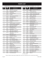
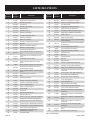
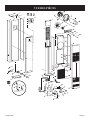
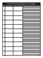
PARTS LIST
PLEASE NOTE: When ordering parts, it is very important that part number and description of part coincide.
INDEX
NO
PART
NO
DESCRIPTION
1 DV1213 TOP PLATE
2 R3165 DOOR CLIP (2 REQUIRED)
3 39476 CASING SIDE - RIGHT
4 DV1202 CASING BACK
5 39476 CASING SIDE - LEFT
6 DV1249 AIR DROP
7 DV1230 TURBULATOR (3 REQUIRED)
8 DV1233 OUTLET BOX REAR
9 DV1224 OUTLET BOX COVER
10 R3161 FAN BLADE
11 R3166 FAN MOTOR
12 DV1246 MOTOR MOUNTING BRACKET
13 R1536 BUSHING
14 R1499 RUBBER GROMMET (4 REQUIRED)
15 R1454 BRASS BUSHING (4 REQUIRED)
16 R3164 DOOR CLIP (2 REQUIRED)
17 DV1251
INNER SHIELD - RIGHT
(INCLUDES NO. 21)
18 R6176 FAN CONTROL SWITCH
19 R3175 LIMIT SWITCH
20 DV1255 INNER SHIELD FRONT (SPP)
20 15666 INNER SHIELD FRONT (IP)
21 DV1253
INNER SHIELD COVER PLATE
(2 REQUIRED)
22 DV1252
INNER SHIELD - LEFT
(INCLUDES NO. 21)
23 DV1257 EXCHANGER ASSEMBLY
24 R3162 FILTER
25 R3163 FILTER RETAINER
26 R3232 PILOT - NATURAL (IP ONLY)
26 R3233 PILOT - PROPANE (IP ONLY)
27 P8852 ORIFICE - NATURAL (3 REQUIRED)
27 P8861 ORIFICE - PROPANE (3 REQUIRED)
28 DV1236 MANIFOLD
29 DV1259 CASING FRONT
30 P112 MANIFOLD UNION
31 R1109 BUSHING (3/8 X 1/2)
31 R9505 BUSHING (1/2 X 3/4) - NATURAL (IP)
32 R3170 GAS VALVE - NATURAL (IP)
32 R3171 GAS VALVE - PROPANE (IP)
32 R2148 GAS VALVE - NATURAL (SSP)
32 R5655 GAS VALVE - PROPANE (SPP)
33 R2708 PIEZO IGNITOR (SPP)
34 DV781
OBSERVATION HOLE COVER WITH
MICA
35 M155 GASKET - OBS HOLE
36 FF160 PIEZO BRACKET (SPP)
37 DV1240 BURNER COMPARTMENT FRONT
38 DV12655 BURNER COMPARTMENT BODY
39 M147 GASKET - TUBE SEAL
40 DV775 SEAL BRACKET (SPP)
40 DV691 SEAL BRACKET (IP)
41 M156 MANIFOLD GASKET
42 DV1235 PILOT BRACKET (IP)
43 R3031 BURNER (3 REQUIRED)
44 DV1239 BURNER BRACKET
45 UH810
TRANSFORMER MOUNTING
BRACKET (SPP)
45 UH452
TRANSFORMER MOUNTING
BRACKET (IP)
46 R1995 TRANSFORMER (SPP)
46 R998 TRANSFORMER (IP)
47 UH451 JUNCTION BOX COVER
48 DV572 JUNCTION BOX
49 R1410 BUSHING
50 R690 CORD SET
51 R1515 BUSHING
52 DV1215 BOTTOM PLATE
53 R3034 PILOT - NATURAL (SPP)
53 R3035 PILOT - PROPANE (SPP)
54 GWT021 PILOT BRACKET (SPP)
55 R3180 ELECTRODE AND WIRE (SPP)
56 R2256 THERMOCOUPLE - 18” (SPP)
58 DV1273 VENT KIT COMPLETE
59 DV1355 FLUE OUTLET TUBE
60 DV1354 AIR INLET TUBE
61 DV131 OUTSIDE MOUNTING PLATE
62 DV769 VENT CAP
N/S DV1261 PILOT TUBING W/FERRULES
N/S R1081 PILOT ORIFICE - NATURAL (SPP)
N/S R1089 PILOT ORIFICE - PROPANE (SPP)
N/S R1233 PILOT ORIFICE - NATURAL (IP)
N/S R3265 PILOT ORIFICE - PROPANE (IP)
N/S R3172 WIRE HARNESS (SPP)
N/S R3173 WIRE HARNESS (IP)
N/S R3236 WIRE (IP)
N/S - NOT SHOWN
INDEX
NO
PART
NO
DESCRIPTION
USE ONLY MANUFACTURER’S REPLACEMENT PARTS. USE OF ANY OTHER PARTS COULD CAUSE INJURY OR DEATH.
La page est en cours de chargement...
La page est en cours de chargement...
La page est en cours de chargement...
La page est en cours de chargement...
La page est en cours de chargement...
La page est en cours de chargement...
La page est en cours de chargement...
La page est en cours de chargement...
La page est en cours de chargement...
La page est en cours de chargement...
La page est en cours de chargement...
La page est en cours de chargement...
La page est en cours de chargement...
La page est en cours de chargement...
La page est en cours de chargement...
La page est en cours de chargement...
La page est en cours de chargement...
La page est en cours de chargement...
La page est en cours de chargement...
La page est en cours de chargement...
La page est en cours de chargement...
La page est en cours de chargement...
La page est en cours de chargement...
La page est en cours de chargement...
La page est en cours de chargement...
La page est en cours de chargement...
La page est en cours de chargement...
La page est en cours de chargement...
-
 1
1
-
 2
2
-
 3
3
-
 4
4
-
 5
5
-
 6
6
-
 7
7
-
 8
8
-
 9
9
-
 10
10
-
 11
11
-
 12
12
-
 13
13
-
 14
14
-
 15
15
-
 16
16
-
 17
17
-
 18
18
-
 19
19
-
 20
20
-
 21
21
-
 22
22
-
 23
23
-
 24
24
-
 25
25
-
 26
26
-
 27
27
-
 28
28
-
 29
29
-
 30
30
-
 31
31
-
 32
32
-
 33
33
-
 34
34
-
 35
35
-
 36
36
-
 37
37
-
 38
38
-
 39
39
-
 40
40
-
 41
41
-
 42
42
-
 43
43
-
 44
44
-
 45
45
-
 46
46
-
 47
47
-
 48
48


Empire Heating Systems Direct-Vent Counterflow Wall Furnace (DVC35) Le manuel du propriétaire
- Taper
- Le manuel du propriétaire
- Ce manuel convient également à
dans d''autres langues
Documents connexes
-
Empire Heating Systems High-Efficiency Wall Furnace (DV20E, DV40E) Le manuel du propriétaire
-
Empire Heating Systems DV-35-2SG Le manuel du propriétaire
-
-
Empire Heating Systems DV-40E-5 Le manuel du propriétaire
-
-
-
-
-
-
Empire Heating Systems Direct-Vent Wall Furnace (DV210/215) Le manuel du propriétaire
Autres documents
-
Empire DV-25-4SG Installation Instructions And Owner's Manual
-
-
Empire Comfort Systems MV 145 Manuel utilisateur
-
Empire DVC-35-2IP Le manuel du propriétaire
-
-
-
-
-
American Hearth DV-822 Le manuel du propriétaire
-