Shure Microflex MX400S Manuel utilisateur
- Catégorie
- Microphones
- Taper
- Manuel utilisateur

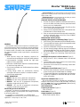
GENERAL
Shure Microflex
r
MX400 Series microphones are miniature goose-
neck-mounted electret condenser microphones designed primarily for
speech and vocal pickup. They can be mounted on lecterns, pulpits,
or conference tables. All models include a preamplifier and are avail-
able with interchangeable cardioid, supercardioid, or omnidirectional
cartridges.
FEATURES
S Wide dynamic range and frequency response for
accurate sound reproduction across the audio spectrum
S Interchangeable cartridges provide the right polar
pattern for every application
S Balanced, transformerless output for increased immunity
to noise over long cable runs
S Shock mount provides over 20 dB isolation from surface
vibration noise
S Locking flange mount for permanently securing
microphone to lecterns, pulpits, or conference tables
S Snap-fit foam windscreen
MODEL VARIATIONS
S MX412: 305 mm (12 in.) gooseneck microphone.
S MX418: 457 mm (18 in.) gooseneck microphone.
S MX412S: 305 mm (12 in) gooseneck microphone;
includes a mute switch and an LED.
S MX418S: 457 mm (18 in) gooseneck microphone;
includes a mute switch and an LED.
SELECTING A POLAR PATTERN
All Microflex
R
microphones are available with any one of three inter-
changeable cartridges. The polar pattern of the cartridge is indicated
by the model number suffix:
/C = Cardioid, /S = Supercardioid, /O= Omnidirectional
Cardioid (C). Recommended for general sound reinforcement
applications. Pickup angle (–3 dB) = 130°.
Supercardioid (S). Recommended for sound reinforcement
applications requiring narrow or more distant coverage. Pickup
angle (–3 dB) = 115°.
Omnidirectional (O). Recommended for recording or remote
monitoring applications. Pickup angle = 360°.
GENERAL INSTALLATION GUIDELINES
1. Aim the microphone toward the desired sound source,
such as the talker, and away from any unwanted sound
source, such as a loudspeaker.
2. Place the tip of the microphone within 15 to 30 cm (6 to
12 in.) of the desired sound source.
3. Always use the supplied windscreen or the optional met-
al windscreen to control breath noise.
4. If four or more microphones will be open at the same time,
use of an automatic mixer, such as the Shure SCM810
or FP410, is recommended.
MICROPHONE INSTALLATION
Installing a Microphone in a Mounting Flange (Figure 2)
1. Drill a 22 mm (7/8 in.) diameter hole in the desired location.
2. Trace and drill three starter holes for the supplied screws
using the flange as a template.
3. Insert the preamplifier through the mounting flange.
4. Slip the mounting flange retaining ring over the bottom
of the preamplifier and slide it up until it is flush to the bot-
tom of the flange. Then press the ring firmly into place.
5. Secure the flange to the mounting surface with three
screws.
Installing a Microphone in a Shock Mount (Figure 1)
1. Drill a 44 mm (1-3/4 in.) diameter hole in the desired
location.
2. Trace and drill three starter holes for the screws using
the shock mount as a template.
3. Secure the shock mount to the mounting surface with
three screws.
Installing the Foam Windscreen (Figure 3)
1. Press the foam windscreen onto the microphone until it
snaps into the groove located below the cartridge.
2. To remove the windscreen, spread the gap in its mounting
ring with a screwdriver or thumbnail and pull the wind-
screen off carefully.
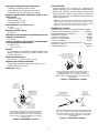
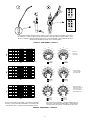
ADJUSTING PREAMP GAIN (Figure 4)
This MX microphone includes an adjustable gain preamplifier, al-
lowing the user to specify a 12 dB or 0 dB gain setting. The preamp
ships at the 12dB setting. Gain may be decreased by 12dB by moving
the preamp jumpers to the 0dB setting.
SPECIFICATIONS
Frequency Response (Figure 5)
50 to 17,000 Hz
Polar Pattern (Figure 5)
Output Impedance (at 1000 Hz)
180 Ω actual (rated at 150 Ω)
Microflex
MX400S Series
User Guide
27F2830 (BG)
2002, Shure Incorporated
Printed in U.S.A.
La page est en cours de chargement...

3
2. En utilisant la bride comme gabarit, marquer et percer
trois trous de guidage pour les vis fournies.
3. Insérer le préampli dans la bride de montage.
4. Insérer la bague de retenue de la bride de montage sur
le bas du préampli et la faire glisser vers le haut jusqu’à
ce qu’elle affleure le base de la bride. Appuyer ferme-
ment sur la bague pour la mettre en place.
Fixation des microphones sur une monture silent-bloc
(Figure 1)
1. Percer un trou de 44 mm de diamètre à l’endroit désiré.
2. En utilisant la monture silent–bloc comme gabarit, mar-
quer et percer trois trous de guidage pour les vis fournies.
3. Assujettir la monture à la surface de montage avec trois vis.
Installation du coupe-vent en mousse (Figure 3)
1. Enfoncer le coupe-vent en mousse sur le microphone
jusqu’à ce qu’il s’encliquette dans la gorge se trouvant
au–dessous de la cartouche.
2. Pour le retirer, écarter les extrémités de la bague de
montage avec un tournevis ou une punaise et le dégag-
er du micro avec précaution.
RÉGLAGE DU GAIN DU PRÉAMPLI (Figure 4)
Ce microphone MX comprend un préamplificateur à gain ré-
glable, ce qui permet à l’utilisateur de choisir un réglage du gain
de 12 dB ou de 0 dB. Le préampli est livré avec le réglage à
12 dB. Le gain peut être diminué de 12 dB en déplaçant les
cavaliers du préampli sur le réglage à 0 dB.
CARACTÉRISTIQUES
Courbe de réponse (Figure 5)
50 à 17 000 Hz
Courbe de directivité (Figure 5)
Impédance de sortie (1000 Hz)
180 Ω réels (nominale à 150 Ω)
Sensibilité en circuit ouvert (à 1 kHz réf. 1V/Pascal*)
Cardioïde : –35,0 dB (17,8 mV)
Supercardioïde : –33,5 dB (21,1 mV)
Omnidirectionnel : –27,5 dB (42,2 mV)
Toutes les configurations –12 dB à 0 gain
*1 Pascal = 94 dB NPA
NPA maximum (1 kHz avec DHT de 1 %, charge de 1 kW)
Cardioïde : 124,2 dB
Supercardioïde : 122,7 dB
Omnidirectionnel : 116,7 dB
Toutes les configurations +6 dB à 0 gain
Bruit de sortie équivalent (pondération en A)
Cardioïde : 28,0 dB NPA
Supercardioïde : 26,5 dB NPA
Omnidirectionnel : 20,5 dB NPA
Rapport signal/bruit (mesuré avec une pression acous-
tique de 94 dB)
Cardioïde : 66,0 dB
Supercardioïde : 67,5 dB
Omnidirectionnel : 73,5 dB
Gamme dynamique avec charge de 1 kW
96,2 dB
100 dB à 0 gain
Rejet en mode commun
45,0 dB au minimum
Atténuation de l’interrupteur de coupure (modèles à in-
terrupteur seulement)
50,0 dB minimum
Niveau d’écrêtage de sortie préampli (1 % DHT)
–6,0 dBV (0,5 V)
–12 dB à 0 gain
Polarité
Une pression acoustique positive sur le diaphragme
produit une tension positive sur la broche 2 par rapport à
la broche 3 du connecteur de sortie.
Alimentation
11 à 52 V c.c. duplex, 2,0 mA
Environnement
Plage de températures de fonctionnement : –18 à 57 _C
Humidité relative : 0 à 95 %
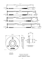
Dimensions (Figure 6)
Homologation
Autorisé à porter la marque CE. Conforme à la directive
CEM européenne 89/336/CEE. Conforme aux critères
applicables de test et de performances de la norme
européenne EN 55103 (1996) parties 1 et 2 pour les
environnements résidentiels (E1) et d’industrie légère
(E2).
REMARQUE : Pour toute information technique par télécopie, composer
le 1–800–488–3297 et suivre les instructions de l’enregistrement. Pour
toute assistance technique supplémentaire, appeler Shure au (847)
866–2200. En Europe, appeler le 49–7131–72140.
PIÈCES DE RECHANGE ET ACCESSOIRES
Coupe-vent en mousse sphérique A99WS. . . . . . . . . . . . . . .
Coupe-vent en métal verrouillable A412MWS. . . . . . . . . . . . . .
Pied de table A412B. . . . . . . . . . . . . . . . . . . . . . . . . . . . . . . . .
Adaptateur de pied A57E. . . . . . . . . . . . . . . . . . . . . . . . . . . . . .
Cartouche omnidirectionnelle R183B. . . . . . . . . . . . . . . . . . .
Cartouche supercardioïde R184B. . . . . . . . . . . . . . . . . . . . . .
Cartouche cardioïde R185B. . . . . . . . . . . . . . . . . . . . . . . . . . .
Coupe-vent encliquetable (4) RK412WS. . . . . . . . . . . . . . . .
Monture silentbloc A400SM. . . . . . . . . . . . . . . . . . . . . . . . . . . .

4
Gebrauchsanleitung für Microflex
R
Schwanenhals-Mikrofone der Reihe MX400
ALLGEMEINES
Shure Microflex
R
Mikrofone der Reihe MX400 sind schwanen-
halsmontierte Mini-Elektretkondensatormikrofone, die in erster Li-
nie für Sprach- und Gesangsaufnahmen vorgesehen sind. Sie
können auf Rednerpulten, Kanzeln oder Konferenztischen befes-
tigt werden. Alle Modelle enthalten einen Vorverstärker und sind mit
austauschbaren Kardioiden-, Superkardioiden- oder Allrichtung-
skapseln lieferbar.
MERKMALE
S Breiter Dynamikbereich und Frequenzgang für genaue
Tonwiedergabe über das gesamte
Tonfrequenzspektrum hinweg
S Austauschbare Kapseln, die ein optimales Polarmuster
für jeden Verwendungszweck ermöglichen
S Ausgeglichene, transformatorlose Ausgabe für erhöhte
Rauschunempfindlichkeit bei langen Kabelführungen
S Schwingdämpfer, der über 20 dB Isolierung von
Oberflächenvibrationsgeräuschen bietet
S Einrastender Befestigungsflansch zur dauerhaften
Anbringung des Mikrofons auf Rednerpulten, Kanzeln
oder Konferenztischen
S Steckrast-Windschirm aus Schaumstoff
MODELLVARIANTEN
MX412: Mikrofon mit 305 mm langem Schwanenhals.
MX418: Mikrofon mit 457 mm langem Schwanenhals.
MX412S: Mikrofon mit 305 mm langem Schwanenhals einschließlich
Stummschalter und LED.
MX418S: Mikrofon mit 457 mm langem Schwanenhals einschließlich
Stummschalter und LED.
AUSWAHL EINER RICHTCHARAKTERISTIK
Alle Microflex
R
-Mikrofone sind mit einer von drei austauschba-
ren Kapseln lieferbar. Das Polarmuster der Kapsel wird durch das
Modellnummer-Suffix angegeben.
/C = Kardioid, /S = Superkardioid, /O= Alle Richtungen
Kardioid (C). Für allgemeine Tonverstärkungsanwendungen
empfohlen. Ansprechwinkel (–3 dB) = 130_.
Superkardioid (S). Für Tonverstärkungsanwendungen empfoh-
len, die eine engere oder weiter entfernte Abdeckung erfordern.
Ansprechwinkel (–3 dB) = 115_.
Alle Richtungen (O). Für Aufzeichnungs- oder Fernüberwachung-
sanwendungen empfohlen. Ansprechwinkel = 360_.
ALLGEMEINE INSTALLATIONSRICHTLINIEN
1. Das Mikrofon auf die gewünschte Schallquelle, wie z.B.
auf den Redner, und weg von unerwünschten Schall-
quellen, wie z.B. einem Lautsprecher, richten.
2. Die Spitze des Mikrofons in einer Entfernung von 15 bis
30 cm von der gewünschten Schallquelle plazieren.
3. Stets den mitgelieferten Windschirm oder wahlweise
den Metall-Windschirm benutzen, um Atemgeräusche
zu unterdrücken.
4. Wenn vier oder mehr Mikrofone gleichzeitig verwendet
werden sollen, ist der Einsatz einer automatischen Misch-
stufe, wie z.B. Shure SCM810 oder FP410, zu empfehlen.
INSTALLATION DES MIKROFONS
Anbringung eines Mikrofons in einem
Befestigungsflansch (Abbildung 2)
1. An der gewünschten Stelle ein Loch mit 22 mm Durch-
messer bohren.
2. Drei Ansatzlöcher für die mitgelieferten Schrauben mar-
kieren und bohren; dabei den Flansch als Schablone be-
nutzen.
3. Den Vorverstärker durch den Befestigungsflansch
einführen.
4. Den Sicherungsring des Befestigungsflansches über
die Unterseite des Vorverstärkers und nach oben schie-
ben, bis er fluchtgerecht zur Unterseite des Flansches
liegt. Danach den Ring fest andrücken.
5. Den Flansch mit drei Schrauben an der Befesti-
gungsfläche festschrauben.
Anbringung eines Mikrofons in einem
Schwingdämpfer (Abbildung 1)
1. An der gewünschten Stelle ein Loch mit 44 mm Durch-
messer bohren.
2. Drei Ansatzlöcher für die Schrauben markieren und boh-
ren; dabei den Schwingdämpfer als Schablone benutzen.
3. Den Schwingdämpfer mit drei Schrauben an der Befes-
tigungsfläche festschrauben.
Anbringung des Schaumstoff-Windschirms (Abbildung 3)
1. Den Schaumstoff-Windschirm auf das Mikrofon
drücken, bis er in die Rille unterhalb der Kapsel einras-
tet.
2. Zum Abnehmen des Windschirms den Spalt in seinem
Befestigungsring mit einem Schraubenzieher oder Dau-
mennagel auseinander spreizen und den Windschirm
vorsichtig abziehen.
EINSTELLUNG DER
VORVERSTÄRKER–VERSTÄRKUNG (Abbildung 4)
Dieses MX–Mikrofon enthält einen Vorverstärker mit Ver-
stärkungseinstellung, der dem Benutzer ermöglicht, eine
12–dB– oder 0–dB–Verstärkungseinstellung zu wählen. Der
Vorverstärker wird mit der 12–dB–Einstellung versandt. Die
Verstärkung kann um 12 dB verringert werden, indem die Vor-
verstärker–Jumper auf die 0–dB–Einstellung verlegt werden.
TECHNISCHE DATEN
Frequenzgang (Abbildung 5)
50 bis 17.000 Hz
Polarmuster (Abbildung 5)
Ausgangsimpedanz (1000 Hz)
Ist–Wert: 180 W (Nennwert: 150 W)
Leerlaufempfindlichkeit (bei 1 kHz, bezogen auf
1 V/Pascal*)
Kardioid: –35,0 dB (17,8 mV)
Superkardioid: –33,5 dB (21,1 mV)
Alle Richtungen: –27,5 dB (42,2 mV)
Alle Einstellungen –12 dB bei Gewinn 0
*1 Pascal = 94 dB Schalldruckpegel
Maximaler Schalldruckpegel (1 kHz bei 1% Klirrfaktor, 1
kW Last)
Kardioid: 124,2 dB
Superkardioid: 122,7 dB
Alle Richtungen: 116,7 dB
Alle Einstellungen +6 dB bei Gewinn 0
La page est en cours de chargement...
La page est en cours de chargement...
La page est en cours de chargement...
La page est en cours de chargement...

9
FIGURE 4 S ABBILDUNG 4 S FIGURA 4
1
2
3
4
5
6
1
2
3
4
5
6
0 dB
12 dB
ADJUSTING PREAMP GAIN (412 AND 418 ONLY) S RÉGLAGE DU GAIN DU PRÉAMPLI (412 ET 418
SEULEMENT) S EINSTELLUNG DER VORVERSTÄRKER–VERSTÄRKUNG(412 UND 418 NUR) S AJUS-
TE DE LA GANANCIA DEL PREAMPLIFICADOR (412 Y 418 SOLAMENTE) S REGOLAZIONE DEL GUA-
DAGNO DEL PREAMPLIFICATORE (412 E 418 SOLTANTO)
150
o
120
o
150
o
120
o
180
o
30
o
60
o
90
o
30
o
60
o
0
150
o
120
o
150
o
120
o
180
o
30
o
60
o
30
o
60
o
–5 dB
0
90
o
–5 dB
–10 dB
–15 dB
90
o
90
o
500 1,000 2,000 5,000 10,000
20,000
50 100 20020
0
+10
–10
500 1,000 2,000 5,000 10,000
20,000
50 100 20020
0
+10
–10
500 1,000 2,000 5,000 10,00050 100 20020
0
+10
–10
250 Hz
500 Hz
1000 Hz
2500 Hz
6400 Hz
10000 Hz
250 Hz
500 Hz
1000 Hz
2500 Hz
6400 Hz
10000 Hz
250 Hz
500 Hz
1000 Hz
2500 Hz
6400 Hz
10000 Hz
150
o
120
o
150
o
120
o
180
o
30
o
60
o
90
o
30
o
60
o
0
150
o
120
o
150
o
120
o
180
o
30
o
60
o
30
o
60
o
–10 dB
–15 dB
0
90
o
–10 dB
–15 dB
–20 dB
90
o
150
o
120
o
150
o
120
o
180
o
30
o
60
o
90
o
30
o
60
o
0
90
o
150
o
120
o
150
o
120
o
180
o
30
o
60
o
90
o
30
o
60
o
0
–5 dB
–10 dB
–15 dB
90
o
90
o
20,000
–20 dB
–5 dB
–10 dB
–15 dB
–20 dB
–5 dB
–20 dB
–5 dB
–20 dB
–20 dB
–15 dB
–10 dB
Hz
Hz
Hz
SUPERCARDIOID
SUPERCARDIOÏDE
SUPERKARDIOID
CARDIOID
CARDIOÏDE
KARDIOID
OMNIDIRECTIONAL
OMNIDIRECTIONNELLE
ALLE RICHTUNGEN
OMNIDIRECCIONAL
OMNIDIREZIONALE
FIGURE 5 S ABBILDUNG 5 S FIGURA 5
TYPICAL FREQUENCY RESPONSE S COURBE DE RÉPONSE
TYPIQUE S TYPISCHER FREQUENZGANG S RESPUESTA DE
FRECUENCIA TIPICA S RISPOSTA IN FREQUENZA TIPICA
TYPICAL POLAR PATTERNS S COURBE DE DIRECTIVITÉ
TYPIQUES S TYPISCHE POLARMUSTER S PATRONES DE
CAPTACION POLAR TIPICOS S DIAGRAM POLARI TIPICI

10
(0.56 in.)
66.70 mm
(2.62 in.)
14.40 mm
FIGURE 6 S ABBILDUNG 6 S FIGURA 6
DIMENSIONS S ABMESSUNGEN S
DIMENSIONES S DIMENSIONI
14.40 mm
(0.56 in.)
(2.00 in.)
50.80 mm
(1.70 in.)
43.18 mm
BEFESTIGUNGSFLANSCH
BRIDA DE MONTAJE
MOUNTING FLANGE
BRIDE DE MONTAGE
FLANGIA DI MONTAGGIO
ASSEMBLAGE DE LA MONTURE SILENT–BLOC
SCHWINGDÄMPFER–BAUGRUPPE
SOPORTE AMORTIGUADO
SUPPORTO ANTIVIBRAZIONE
SHOCK MOUNT ASSEMBLY
38 mm
(1.5 in.)
(Actual Size)
11.68 mm
(0.46 i n.)
11.68 mm
(0.46 i n.)
11.68 mm
(0.46 i n.)
11.68 mm
(0.46 i n.)
428.74 mm
(16.88 i n.)
330.70 mm
(13.02 i n.)
98.04 mm
(3.86 i n.)
20.07 mm
(0.79 i n.)
20.07 mm
(0.79 i n.)
20.07 mm
(0.79 i n.)
20.07 mm
(0.79 i n.)
468.11 mm
(18.43 i n.)
333.87 mm
(13.14 i n.)
134.24 mm
(5.28 i n.)
571.44 mm
(22.50 i n.)
473.40 mm
(18.64 i n.)
98.04 mm
(3.86 i n.)
607.64 mm
(23.92 i n.)
473.40 mm
(18.64 i n.)
134.24 mm
(5.28 i n.)
MX412
MX412S
MX418
MX418S

11
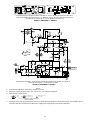
FIGURE 7 S ABBILDUNG 7 S FIGURA 7
MX412/MX418 CIRCUIT BOARD LEGEND S LÉGENDE DU CIRCUIT IMPRIMÉ MX412/MX418 S BESCHRIF-
TUNG DER MX412/MX418 LETTERPLATTE S LEYENDA DE TARJETA DE CIRCUITOS DE MX412/MX418 S
LEGENDA DELLA SCHEDA DI CIRCUITI DEI MODELLI MX412/MX418
FIGURE 8 S ABBILDUNG 8 S FIGURA 8
MX412/MX418 SCHEMATIC S MX412/MX418 SCHÉMA S MX412/MX418 DIAGRAMM S MX412/MX418
DIAGRAMA ESQUEMÁTICO S MX412/MX418 SCHEMA
R27
100
R1
100
R28
100
R2
100
A.C. Voltage
D.C. Voltage
A.C. Voltage, Mic Off
D.C. Voltage, Mic Off
Printed Clrcuit Ground
Case Ground
(+) / (–) indicate A.C. polarity relative to
input test signal.
NOTES:
1. All resistors1/10 Watt, 1%, 0805 unless otherwise specified.
2. Electrolytic capacitors shown in µF, ±10%, 50V or more, unlss otherwise specified.
3. The following symbols denote:
4. All voltages measured with input driven by a 0.1 Vrms, 1kHz signal through the test circuit shown below. A Shure M367 mixer or
equivalent, with 48 V phantom power switched on, supplies the required power and load to preamplifier.

12
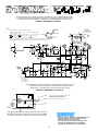
FIGURE 9 S ABBILDUNG 9 S FIGURA 9
MX412S/MX418S CIRCUIT BOARD LEGEND S LÉGENDE DU CIRCUIT IMPRIMÉ MX412S/418S S
BESCHRIFTUNG DER MX412S/418S LEITERPLATTE S LEYENDA DE TARJETA DE CIRCUITOS
DE MX412S/418S S LEGENDA DELLA SCHEDA DI CIRCUITI DEI MODELLI MX412S/418S
FIGURE 10 S ABBILDUNG 10 S FIGURA 10
MIC OUT
USCITA MICROFONO
MIKRO AUS
SORTIE MICRO
SALIDA DE MICROFONO
SIDE 1 CÔTÉ 1 SEITE 1 LADO 1 LATO 1
SIDE 2 CÔTÉ 2 SEITE 2 LADO 2 LATO 2
MX412S/MX418S SCHEMATIC DIAGRAM S SCHÉMA DE PRINCIPE MX412S/418S S
STROMLAUFPLAN FÜR MX412S/418S S DIAGRAMA ESQUEMATICO DEL
MX412S/418S S SCHEMA CIRCUITALE DEI MODELLI MX412S/418S
FROM CARTRIDGE
DE LA CARTOUCHE
DEL CARTUCHO
DALLA CARTUCCIA
ON DER KAPSEL
A.C. Voltage
D.C. Voltage
A.C. Voltage, Mic Off
D.C. Voltage, Mic Off
Printed Clrcuit Ground
Case Ground
(+) / (–) indicate A.C. polarity relative to input test signal.
NOTES:
1. All resistors1/10 Watt, 1%, 0805 unless otherwise specified.
2. Electrolytic capacitors shown in µF, ±10%, 50V or more, unless otherwise specified.
3. The following symbols denote:
4. All voltages measured with input driven by a 0.1 Vrms, 1kHz signal through the test circuit shown below. A Shure M367
mixer or equivalent, with 48 V phantom power switched on, supplies the required power and load to preamplifier.
1 kHz
0.1 Vrms
W
W
W
MIC
ELEMENT
220 pF
220 pF
FET
86E8958
J1/W1 WHITE/SHIELD BLANC/BLINDAGE WEIß/SCHILD
BLANCO/BLINDAJE BIANCO/SCHERMATURA
J2/W2 RED ROUGE ROT ROJO ROSSO
J3/W3 BLACK NOIR SCHWARZ NEGRO NERO
J1/W1
J2/W2
J3/W3
MICROPHONE WIRING DIAGRAM S SCHÉMA DE CÂBLAGE DU MI-
CROPHONE S MIKROFONSCHALTPLAN S DIAGRAMA DE ALAMBRA-
DO DEL MICROFONO S SCHEMA CIRCUITALE DEL MICROFONO
SHURE Incorporated Web Address: http://www.shure.com
222 Hartrey Avenue, Evanston, IL 60202–3696, U.S.A.
Phone: 847-866–2200 Fax: 847-866-2279
In Europe, Phone: 49-7131-72140 Fax: 49-7131-721414
In Asia, Phone: 852-2893-4290 Fax: 852-2893-4055
Elsewhere, Phone: 847-866–2200 Fax: 847-866-2585
-
 1
1
-
 2
2
-
 3
3
-
 4
4
-
 5
5
-
 6
6
-
 7
7
-
 8
8
-
 9
9
-
 10
10
-
 11
11
-
 12
12


Shure Microflex MX400S Manuel utilisateur
- Catégorie
- Microphones
- Taper
- Manuel utilisateur
dans d''autres langues
- italiano: Shure Microflex MX400S Manuale utente
- English: Shure Microflex MX400S User manual
- español: Shure Microflex MX400S Manual de usuario
- Deutsch: Shure Microflex MX400S Benutzerhandbuch
Documents connexes
-
Shure MX400S Manuel utilisateur
-
-
-
-
-
-
-
-
-
Autres documents
-
Lexicon MX400 Le manuel du propriétaire
-
Behringer MX400 Le manuel du propriétaire
-
Electro-Voice CP218 Manuel utilisateur
-
-
Donner DC 87 Manuel utilisateur
-
-
Sennheiser Super-Cardioid Dynamic MD 412 Manuel utilisateur
-
LiftMaster CAPXS Guide d'installation