HQ Power Krystal RGV380 RGV laser projector Manuel utilisateur
- Catégorie
- Stroboscopes
- Taper
- Manuel utilisateur
Ce manuel convient également à

V
K
R
K
R
P
R
P
R
K
R
U
S
G
E
N
O
M
A
B
E
DP230
1
R
YSTAL
R
YSTAL
R
OJECT
E
R
OYECT
O
R
YSTAL
S
ER MAN
E
BRUIKE
R
O
TICE D’
E
A
NUAL D
E
DIENUN
1
RGVL
D
RGV /
R
RGV /
R
E
UR LAS
E
O
R L
Á
S
E
RGV- /
R
UA
L
R
SHAND
L
E
MPLOI
EL USUA
R
GSANLEI
T
D
10 -
V
R
GY LAS
E
R
GY LAS
E
E
R KRY
S
E
R KRYS
T
R
GY-LA
S
L
EIDING
R
IO
T
UNG
V
DP260
E
R PROJ
E
E
RPROJ
E
S
TAL RG
V
T
AL RG
V
S
ERSCH
E
3
11
19
27
35
1RGYL
D
E
CTO
R
-
E
CTOR -
M
V
/ RGY
V
/ RGY-
E
INWER
F
D
10 -
V
with S
D
M
ET SD
-
- AVEC
C
CON TA
R
F
ER - MI
T
V
DP380
D
CARD
-
KAART
C
ARTE S
R
JETA S
D
T
SD-K
A
1RGVL
D
D
D
A
RTE
D
10

11
H
o
C
o
M
o
M
o
Di
e
/08/2011
o
w to turn
t
o
ntroller li
n
o
difier la li
g
o
dificar la l
e
Controll
e
VDP
2
t
he control
n
e van 3-pi
n
g
ne du con
t
ínea del c
o
e
r-Linie vo
n
2
301RGVL
D
ler line fro
m
n
naar 5-pi
t
rôleur de
3
o
ntrolador
d
n
3-Pin nac
h
D
10 - VDP2
6
m
3-pins i
n
n aanpass
e
3
broches
e
d
e 3 polos
y
h
5-Pin an
z
6
01RGYLD
1
2
n
to 5-pins
(
e
n (stekke
r
e
n 5 broch
e
y
5 polos (
c
z
upassen (
S
1
0 - VDP3
8
(
plug and s
r
en contac
t
e
s (fiche e
t
c
onector y
S
tecker un
d
8
01RGVLD
1
termi
n
eindweers
t
résistan
c
termin
a
termin
a
Terminie
r
ocket).
t
).
t
contact).
contacto).
d
Kontakt)
.
1
0
n
ator
t
and
c
e de
a
ison
a
ción
r
ung
.
©Vellema
n
n
nv

11
1
.
T
o
I
m
Th
If
t
Th
op
As
2
.
•
•
•
•
/08/2011
.
Introd
u
o
all reside
n
m
portant e
n
This
har
m
shou
distri
If in
ank you for
t
he device
w
e VDP230
1
erated in 3
m
sociation) s
t
VDP2
3
VDP3
8
VDP2
6
.
Safety
I
Be
Do
Ke
e
Un
p
Us
e
Wh
NE
V
ey
e
Do
Ke
e
VDP23
0
VDP38
0
VDP26
0
Damage ca
dealer will
n
A qualified
Do not swi
t
device agai
This device
qualified p
e
VDP
2
u
ction
n
ts of the
E
n
vironmen
t
symbol on t
h
m
the enviro
n
ld be taken
t
butor or to
a
doubt, co
n
choosing H
Q
w
as damage
d
1
RGVLD10,
m
odes: DM
X
t
andard mo
d
3
01RGVLD
1
8
01RGVLD
1
6
01RGYLD
1
I
nstruct
very careful
not touch t
h
e
p this devi
c
p
lug the ma
i
e
extreme c
a
en device is
V
ER point t
h
e
s or skin. B
not point t
h
e
p out of re
a
0
1RGVLD1
0
0
1RGVLD1
0
0
1RGYLD1
0
used by dis
r
n
ot accept r
e
technician s
t
ch the devi
c
nst damage
falls under
e
rson carry
o
2
301RGVL
D
E
uropean U
n
t
al informa
t
h
e device o
r
n
ment. Do n
t
o a speciali
a
local recy
c
n
tact your l
Q
-power! Pl
e
d
in transit,
VDP2601
R
X
/sound con
t
d
e. Each pro
j
1
0: 230mW
1
0: 380mW
1
0: 260mW
ions
during the
h
e device d
u
c
e away fro
m
i
ns lead bef
o
a
ution when
in use, do
N
h
e laser bea
urns and pe
h
e laser bea
m
a
ch of all chi
Th
e
AV
O
AP
E
0
0
0
r
egard of ce
r
e
sponsibilit
y
hould instal
l
c
e on imme
d
by leaving
i
protection c
o
ut the elec
t
D
10 - VDP2
6
Us
e
n
ion
t
ion about
t
r
the packag
ot dispose
o
zed compan
c
ling service
.
ocal waste
e
ase read th
do not insta
R
GYLD10 a
n
t
rolled, SD
c
j
ector has 1
RGV (Red
G
RGV (Red
G
RGY (Red
G
installation:
u
ring operati
m
rain and
m
o
re opening
the laser b
e
N
OT look d
m directly
o
rmanent ey
e
m
towards h
ldren.
e
arrow indi
c
O
ID EXPO
S
E
RTURE
r
tain guideli
n
y
for any en
s
l
and servic
e
d
iately after
i
t switched
o
lass I. It is
t
t
ric connecti
o
6
01RGYLD
1
3
e
r man
t
his produ
c
e indicates
t
o
f the unit (
o
y for recycli
.
Respect th
e
disposal a
e manual th
ll or use it a
n
d VDP380
1
c
ard mode o
0 DMX chan
G
reen Violet
)
G
reen Violet
)
G
reen) laser
touching li
v
on as the h
o
m
oisture.
the housing
e
am is turn
e
irectly or i
n
o
r via a refle
c
e
damage w
ighly explos
c
ates the las
S
URE - LAS
E
n
es in this
m
s
uing defect
s
e
this device
it has been
o
ff until it h
a
t
herefore es
s
o
n.
1
0 - VDP3
8
ual
c
t
t
hat disposa
o
r batteries)
ng. This de
v
e
local envi
r
uthorities.
oroughly be
nd contact
y
1
RGVLD10
r via PC – I
L
nels (6 in S
D
)
laser proje
c
)
laser proje
c
projector
v
e wires can
o
using heat
s
.
e
d on.
n
directly (
r
c
ting surfac
e
ill result.
ive gasses.
er aperture.
E
R RADIAT
m
anual is no
t
s
or proble
m
.
exposed to
c
a
s reached r
o
s
ential that
t
8
01RGVLD
1
l of the devi
as unsorte
d
v
ice should
b
r
onmental r
u
fore bringin
g
y
our dealer.
are laser pr
o
L
DA (Intern
a
D
card mod
e
c
tor
c
tor
cause life-t
h
s
up.
r
eflectance
e
towards o
t
ION IS EM
I
t
covered b
y
m
s.
c
hanges in
t
o
om temper
t
he device b
1
0
ce after its l
d
municipal
w
b
e returned
t
u
les.
g
this devic
e
o
jectors tha
t
a
tional Lase
r
e
).
h
reatening
e
) into the l
a
t
her people’
s
I
TTED FRO
y
the warran
t
emperature
ature.
e earthed.
H
©Vellema
n
ifecycle cou
l
w
aste; it
t
o your
e
into servic
e
t
can be
r
Display
e
lectroshock
s
a
ser beam
.
s
or animals
’
M THIS
ty and the
. Protect th
e
H
ave a
n
nv
l
d
e
.
s
.
.
’
e

VDP2301RGVLD10 - VDP2601RGYLD10 - VDP3801RGVLD10
11/08/2011 ©Velleman nv
4
• Make sure that the available voltage does not exceed the voltage stated in the specifications of this manual.
• Do not crimp the power cord and protect it against damage. Have an authorised dealer replace it if
necessary.
• Disconnect the device from the mains to clean it or when it is not in use. Handle the power cord by the plug
only.
• Keep the device away from splashing and dripping liquids. Never put objects filled with liquid on top of the
device.
• Note that damage caused by user modifications to the device is not covered by the warranty.
• Mechanical wear is not covered by warranty.
• Keep the device away from children and unauthorised users.
3. General Guidelines
Refer to the Velleman® Service and Quality Warranty on the last pages of this manual.
• Nor Velleman nv nor its dealers can be held responsible for any damage (extraordinary, incidental or
indirect) – of any nature (financial, physical…) arising from the possession, use or failure of this product.
• This device is designed for professional use on stage, in discos, theatres, etc. The laser projector should
only be used indoors with an alternating current of max. 230VAC / 50Hz.
• Lighting effects are not designed for permanent operation: regular operation breaks will prolong their lives.
• Do not shake the device. Avoid brute force when installing or operating the device.
• Select a location where the device is protected against extreme heat, dust and moisture.
• Use an appropriate safety cable to fix the device (e.g. VDLSC7 or VDLSC8).
• Familiarise yourself with the functions of the device before actually using it. Do not allow operation by
unqualified people. Any damage that may occur will most probably be due to unprofessional use of the
device.
• Use the original packaging if the device is to be transported.
• All modifications of the device are forbidden for safety reasons.
• Only use the device for its intended purpose. All other uses may lead to short circuits, burns, electroshocks,
crash, etc. Using the device in an unauthorised way will void the warranty.
4. Mounting/connecting the device
• Have the device installed by a qualified person, respecting EN 60598-2-17 and all other applicable norms.
• The carrying construction must be able to support 10 times the weight of the device for 1 hour without
deforming.
• The installation must always be secured with a secondary attachment e.g. a safety cable.
• Never stand directly below the device when it is being mounted, removed or serviced. Have a qualified
technician check the device once a year and once before you bring it into service.
• Install the device in a location with few passers-by that is inaccessible to unauthorised persons.
• Overhead mounting requires extensive experience: calculating workload limits, determining the installation
material to be used… Have the material and the device itself checked regularly. Do not attempt to install the
device yourself if you lack these qualifications as improper installation may result in injuries.
• Adjust the desired inclination angle via the mounting bracket and tighten the bracket screws.
• Make sure there is no flammable material within a 0.5m radius of the device.
• Have a qualified electrician carry out the electric connection.
• Connect the device to the mains with the power plug. Do not connect it to a dimming pack.
• The installation has to be approved by an expert before the device is taken into service.
• For installations using DMX512:
• Connection
Connect the provided XLR cable to the female 3-pin XLR output of your controller and the other side to
the male 3-pin XLR input of the laser projector [7]. Multiple laser projectors can be linked through serial
linking. The linking cable should be a two-core screened cable with XLR input and output connectors (see
page 2 for pin-out).
• Chain with Termination
A DMX terminator is recommended for installations where the DMX cable has to run a long distance or is
in an electrically noisy environment (e.g. discos). The terminator prevents corruption of the digital control
signal by electrical noise. The DMX terminator is simply an XLR plug with a 120Ω resistor between pins 2
and 3, which is then plugged into the XLR output socket [8] of the last device in the chain (see page 2).
• For installations using ILDA (PC mode) use following ILDA cable layout (DB-25F):
PIN signal name remarks
1 X+ -5V to +5V
2 Y+ -5V to +5V
5 Red+ 0V to 2.5V
6 Green+ 0V to 2.5V
14 X- Connected to ground
15 Y- Connected to ground
18 Red- Connected to ground
19 Green- Connected to ground
25 Ground Cable shield

11
5
.
Re
2
3
4
5
6
7
8
9
1
1
1
1
6
.
Re
•
•
6.
•
•
/08/2011
.
Descri
p
fer to the ill
1 MIC
2
VOLUM
E
3
READY
ERROR
4
FUNC S
E
5
SD CAR
6
MODE
S
7
DMX IN
8
DMX O
U
9
DIP SW
I
1
0 ILDA IN
1
1 ILDA T
H
1
2 ON/OF
F
1
3 AC IN
~
.
Use
f
er to the ill
The laser p
o Sound/
D
o SD card
o PC cont
r
Select the
d
1 Sou
n
Press the S
Use the DI
P
o Sound
/
auto an
d
o DMX c
o
DMX st
a
• Star
t
All D
M
sign
a
cont
r
You
c
ever
y
Whe
n
parti
c
VDP
2
p
tion
ustrations o
E
DMX
DATA
E
LECT UP
D SLOT
S
WITCHES
U
T
I
TCH
H
RU
F
*
~
ustrations o
rojector can
D
MX controll
controlled
r
olled (via I
L
d
esired mod
n
d/DMX
c
OUND&DM
X
P
switch [9]
/
auto/slav
e
d
slave mod
e
Fu
n
sou
n
aut
o
slav
cou
n
o
ntrol mod
e
a
rt address (
addr
e
5
19
40
t
Address
S
M
X-controll
e
a
ls. This sta
r
r
oller.
c
an use the
s
y
device.
n
all devices
c
ular chann
e
2
301RGVL
D
n page 2 of
microph
volume
status L
SD card
slot for
S
select o
p
DMX in
p
DMX ou
t
set the
D
ILDA st
a
ILDA st
a
on/off k
e
AC inpu
t
n page 2 of
work in 3 d
ed
L
DA standar
d
e by pressi
n
c
ontrolle
d
X
mode swit
c
to configur
e
e
mode: sw
i
e
.
n
ction
n
d mode (m
o
mode
e mode
n
tdown mod
e
: switch 10
max. 511).
e
ss
D
S
etting
e
d devices n
e
r
t address is
s
ame starti
n
have the s
a
e
l. In other
w
D
10 - VDP2
6
this manual
one
control
EDs for SD
c
controls
S
D card
p
erating mo
d
p
ut port (3 p
t
put port (3
D
MX addres
s
a
ndard inpu
t
a
ndard sign
a
e
y switch
t
110~240V
a
* depe
n
this manual
ifferent mo
d
d
)
n
g the corre
s
d
mode
c
h [6] to se
l
e
sound or
D
i
tch 10 mus
t
aster)
e*
* the la
must be se
t
Examples:
D
IP Switch
e
e
ed a digita
l
the channe
l
n
g address f
o
a
me addres
s
w
ords: chan
g
6
01RGYLD
1
5
.
c
ard mode
d
e
ins)
pins
s
t
a
l throughpu
a
c 50/60Hz
n
ding on th
e
.
d
es:
s
ponding m
o
l
ect Sound/
D
D
MX mode:
t
be set to t
h
ser projects
t
to the ON
p
e
s
l
start addr
e
l
number fr
o
o
r a whole
g
s
, all laser p
r
g
ing the set
t
1
0 - VDP3
8
t
(and fuse h
o
e
model an
a
o
de switch [
6
D
MX controll
h
e OFF posi
t
DIP Sw
a countdo
w
p
osition. Sw
i
s
w
e
ss so that t
h
o
m which th
e
g
roup of dev
i
r
ojectors wil
l
t
ings of one
8
01RGVLD
1
o
lder)
a
dditional o
n
6
].
ed mode.
t
ion. Switch
e
itches
w
n sequence
i
tches 1 thr
o
w
itch
1
2
3
4
5
6
7
8
9
h
e correct d
e
e
device sta
r
i
ces or ente
r
l
“listen” to
t
channel wil
l
1
0
n
/off switch
m
e
s 1 and 2 t
h
from 9 to 0
o
ugh 9 than
represe
n
1
2
4
8
16
32
64
128
256
e
vice respo
n
r
ts to
“
listen
r
an individ
u
t
he control
s
l
affect all d
e
©Vellema
n
m
ay be pre
s
h
an determi
n
.
determine
t
n
ts
n
ds to the
” to the DM
X
u
al one for
s
ignal on on
e
e
vices
n
nv
s
ent
n
e
t
he
X
e

VDP2301RGVLD10 - VDP2601RGYLD10 - VDP3801RGVLD10
11/08/2011 ©Velleman nv
6
simultaneously. If you set different addresses, each device will “listen” to a separate channel number.
Changing the settings of one channel will only affect the device in question.
In the case of the 10-channel laser projector, you will have to set the start address of the first laser
projector to 1, the second laser projector to 11 (10 + 1), the third to 21 (10 + 11) and so on.
• DMX5 channel assignment
Channel DMX512
value
function
1 control mode
0--63 Sound control (channel 3~10 not used)
64--127 Auto mode (channel 3~10 not used)
128--191 DMX control
192--255 Auto mode
2 blanking & blackout
VDP2301RGVLD10
VDP3801RGVLD10
VDP2601RGYLD10
0--5 blackout blackout
6--10 white
red
11--15 red
16--25 yellow
green
21--25 green
26--30 cyan
yellow
31--35 blue
36--40 purple 36--105 single colour (auto)
41--110 single colour (auto) 106--175 tri-colour (auto)
111--180 multi-colour (auto) 176--245 tri-colour (move)
181--251 multi-colour (move) 246--255 bounded colour
251--255 bounded colour
3 pattern 0--255 124 patterns (0-255)
4 vertical move
0--127 manual vertical move
128--191 auto down, speed up accordingly
192--255 auto up, speed up accordingly
5 horizontal move
0-127 manual horizontal move
128--191 manual right, speed up accordingly
192-255 manual left, speed up accordingly
6 vertical roll
0--127 manual vertical rotation
128--255 auto vertical rotation, speed up accordingly
7 horizontal roll
0--127 manual horizontal rotation
128--255 auto horizontal rotation
8 rotation
0--127 manual rotation
128--191 auto clockwise rotation, speed up accordingly
192--255 auto anti-clockwise rotation, speed up accordingly
9 zoom in & out
0--85 from small to large, speed up accordingly
86--170 from large to small, speed up accordingly
171--255
large ←→ small, speed up accordingly
10 point draw 0--255 0=nil / 1~255=faint ~bright
6.2 SD Card controlled mode
• Press the SD CARD mode switch [6] to select SD CARD controlled mode.
• In SD CARD mode, a DMX address (and thus a controller) is still required.
SD card notes:
• Only use high quality SD cards of well known brands to avoid reading errors.
• Max. supported capacity = 2GB.
• The card must be formatted as FAT16 file system. The card that comes with the device is already correctly
formatted.
• Do not place files in sub-directories.
• Do not place more than 260 files in the root directory.
• File name length is limited to 8 characters (followed by the .ild extension).
• 5animated) files (shows) must be created using an appropriate ILDA software program (not included).
• The root directory may contain 3 reserved files. Do not remove these files:
o CONFIG.DAT: contains setting information for the laser projector. See further for instructions on creating
and modifying this file.
o FLASHMP.BIN: control program for firmware updates

VDP2301RGVLD10 - VDP2601RGYLD10 - VDP3801RGVLD10
11/08/2011 ©Velleman nv
7
o FWUPxxx.BIN: specific update (xxx=update number). This file is removed automatically when the update
procedure is completed.
Definitions:
• A show contains a number of frames which are played (projected) in sequence.
• Each frame is drawn by a laser as a series of points. The time between the points determine the
smoothness of the frame. The overall speed is expressed in Kilo points per second (Kpps). When this value
is set too low, the frame will not be completely visible or flickers.
Note: setting the speed at max. (= 20Kpps) all the time puts a lot of stress on the internal moving parts of
the projector.
• The time between to consecutive frames (= the speed of the animation) is set by the frame repeat
parameter. A low (DMX-) value will produce a low animation speed.
Note: running the animations at max. speed all the time puts a lot of stress on the internal moving parts of
the projector.
• When the laser has to draw two non-consecutive points, it will switch off for a brief period of time, the so
called blank shift. A low value will switch off the laser immediately at one point and switch it on again in
the next; increasing the value will delay laser switching.
DMX channels:
• In SD CARD mode, the laser projector becomes a 16-channel DMX device. However, only 9 of these
channels can be controlled, the other ones are defined by the projected animation.
• Use the output of the DMX-controller (not incl.) to control the channels. Refer to CONFIG.DAT below for an
overview of the DMX channels.
SD card controls:
• There are 3 buttons to control the SD card mode:
o FUNC [A]
Select the parameter to change:
“Adr” = DMX address (1~512)
“Int” = max. colour/laser output intensity (0~99).
“Ort” = orientation of the projection (0~7)
0 normal 4 X and Y swapped
1 X inverted 5 X and Y swapped; X inverted
2 Y inverted 6 X and Y swapped; Y inverted
3 X and Y inverted 7 X and Y swapped, X and Y inverted
o SEL [B]
Press this button to see the current setting of “Adr”, “Int” or “Ort”.
Press again to edit the setting. The right digit starts blinking and can be changed using the UP button.
Press SEL again to edit the middle digit; press again to edit the left digit. Press FUNC to store and exit.
o UP [C]
Press this button to increase the value of the blinking digit (0~9).
Note: the LCD will return to normal display after 10s of inactivity
Status LEDs:
• Refer to the table below for the meaning of the status LEDs.
READY
(green)
DMX
(green)
ERROR
(red)
DATA
(yellow)
X no MMC/SD card present
X X no FAT16 file system found
X X X data error while reading card
X X file not found or invalid
X X no DMX signal
X X laser projector ready
Note: X = ON
• Not every error will cause the laser output to stop. This will only be the case when access or read/write
errors on the memory card occur or files are corrupted.
CONFIG.DAT:
• The file CONFIG.DAT contains configuration information for the laser projector. It can be created and
modified by using the software tool EditConfig.exe which is shipped with every laser projector.
• Insert the included SD card in a suitable PC, locate EditConfig.exe and double click it to open the
configuration file:

VDP2301RGVLD10 - VDP2601RGYLD10 - VDP3801RGVLD10
11/08/2011 ©Velleman nv
8
• To start a new configuration, select New Config; to adjust and existing configuration, click Load Config.
Select the desired file in the pop-up window.
Global data:
• Set the DMX base address of the laser projector between 1 and 511.
When multiple laser projectors are linked, and they must produce the same output, their addresses must
be set to the same value and their CONFIG.DAT files must be identical.
If they are controlled individually, their addresses must be separated by 16 as each device needs 16 DMX
channels. So the first should be at 1, the second at 17 the third on 33 and so on.
DMX-Channels 1-16:
• Define the DMX channel numbers to control the laser animation. Every function must have a unique
channel number (1~16).
• Except for the first two parameter (show select L and show select H) all parameters can be set to a
fixed value by checking the none-box and entering the desired value in the dropdown box behind the
parameter or in the showtable below the parameters. In this case, the parameter can not be changed via
DMX anymore.
• The Show Select H parameter can be set to none by checking the checkbox. By doing this, only the first
16 files in the showtable are accessible.
show select L Select one of the first 16 shows on the card (including pause). Each show occupies
16 DMX values.
show select H Select one of the 16 banks of shows, each bank containing 16 shows (total=256
shows). A bank uses 16 DMX values.
Speed Kpps Set the frame drawing speed (Kpps).
Note: this setting might influence the blank shift setting.
Frame repeat Control the animation speed.
projection size Change the size of the projection (see important note below).
Changing the size too fast will result in a ‘jumping’ display.
offset X 0 = maximum negative offset
128 = centre position
255 = maximum positive offset
Note: projected display might ‘jump’ due to the slow DMX signal rate
offset Y 0 = maximum negative offset
128 = centre position
255 = maximum positive offset
Note: projected display might ‘jump’ due to the slow DMX signal rate
Blank shift Control the laser off-time between non-consecutive points of the frame.
Intensity Control the intensity of the laser output.

VDP2301RGVLD10 - VDP2601RGYLD10 - VDP3801RGVLD10
11/08/2011 ©Velleman nv
9
IMPORTANT NOTE
Setting the projection size to zero can cause a standing laser beam. This is a hazardous
condition that must be avoided at all times.
Showtable:
Note: the show in the first data entry field, DMX value 0, is displayed when the laser projector is paused
or when an empty data location (no filename provided) is opened. For safety reasons it is strongly
advised to leave this empty.
• Enter up to 256 shows into the filename-fields. Click on a filename field to open an explorer dialog box.
Select the desired .ild file.
Note: the .ild file must be on the SD card.
Notes:
• Every show occupies 16 DMX values. The relationship between DMX control and DMX Value (=
filename) is given in the table below:
Showselect H
0-
15
16-
31
32-
47
48-
63
64-
79
80-
95
96-
111
112-
127
128-
143
144-
159
160-
175
176-
191
192-
207
208-
223
224-
239
240-
255
Showselect L
240-255 15 31 47 63 79 95 111 127 143 159 175 191 207 223 239 255
224-239 14 30 46 62 78 94 110 126 142 158 174 190 206 222 238 254
208-223 13 29 45 61 77 93 109 125 141 157 173 189 205 221 237 253
192-207 12 28 44 60 76 92 108 124 140 156 172 188 204 220 236 252
176-191 11 27 43 59 75 91 107 123 139 155 171 187 203 219 235 251
160-175 10 26 42 58 74 90 106 122 138 154 170 186 202 218 234 250
144-159 9 25 41 57 73 89 105 121 137 153 169 185 201 217 233 249
128-143 8 24 40 56 72 88 104 120 136 152 168 184 200 216 232 248
112-127 7 23 39 55 71 87 103 119 135 151 167 183 199 215 231 247
96-111 6 22 38 54 70 86 102 118 134 150 166 182 198 214 230 246
80-95 5 21 37 53 69 85 101 117 133 149 165 181 197 213 229 245
64-79 4 20 36 52 68 84 100 116 132 148 164 180 196 212 228 244
48-63 3 19 35 51 67 83 99 115 131 147 163 179 195 211 227 243
32-47 2 18 34 50 66 82 98 114 130 146 162 178 194 210 226 242
16-31 1 17 33 49 65 81 97 113 129 145 161 177 193 209 225 241
0-15 0 16 32 48 64 80 96 112 128 144 160 176 192 208 224 240
• Set the desired frame drawing speed, framerepeat and display mode by clicking on either one of those
fields:
Displaymode
oneshot/complete The show is shown 1 time completely. It can not be interrupted. When
finished, the projector goes into pause mode.
oneshot/interruptable The show is shown 1 time completely. It can be interrupted via DMX. When
finished, the projector goes into pause mode.
loop/complete The show is shown in a continuous loop. It can only be interrupted at the
end of the show.
loop/interruptable The show is shown in a continuous loop. It can be interrupted at any time
via DMX.

VDP2301RGVLD10 - VDP2601RGYLD10 - VDP3801RGVLD10
11/08/2011 ©Velleman nv
10
• Click on No File to remove the file from the list.
• Click OK to save the settings.
• When desired, a list of all DMX settings can be printed by clicking the Print button.
• To save the configuration, click on Save Config. The file must be saved as CONFIG.DAT as this is the
file that will be loaded automatically by the laser projector.
• Place the SD card back in the laser projector and switch the projector on. Make sure the SD CARD mode
switch [6] is pressed and the correct DMX address is set via the SD card controls.
6.3 PC controlled mode
• The PC controlled mode uses the ILDA (International Laser Display Association) standard for control signal
and file formats. The laser projector must be connected to a suitable PC running appropriate software (e.g.
Pangolin, Mamba, Phoenix…). Refer to §5 for the cable layout of the ILDA cable. More on the ILDA standard
can be found on http://www.laserist.org/standards.htm
.
IMPORTANT NOTE
Make sure to set the scan rate in the software equal to or lower than the actual scan rate of
the laser projector. Setting the scan rate too high may damage the laser projector; this
damage is not covered by the warranty.
• Press the PC MODE switch [6] to select PC mode.
• In this mode, the laser projector will receive its instructions and shows via the ILDA input port [10].
• Multiple laser projectors can be linked via the ILDA THRU port [9].
7. Cleaning and Maintenance
• All screws should be tightened and free of corrosion.
• The housing, visible parts, mounting supports and the installation location (e.g. ceiling, suspension,
trussing) should not be deformed, modified or tampered with e.g. do not drill extra holes in mounting
supports, do not change the location of the connections.
• Moving mechanic parts must not show any signs of wear and tear.
• The electric power supply cables must not show any damage. Have a qualified technician maintain the
device.
• Disconnect the device from the mains prior to maintenance activities.
• Wipe the device regularly with a moist, lint-free cloth. Do not use alcohol or solvents.
• There are no user-serviceable parts apart from the fuse.
• Contact your dealer for spare parts if necessary.
8. Technical specifications
VDP2301RGVLD10 VDP3801RGVLD10 VDP2601RGYLD10
Laser colour
/power
red 663nm/160mW 665nm/215mW 662nm/200mW
green 533nm/100mW 533nm/85mW 533nm/100mW
purple 408nm/200mW 405nm/200mW -
max. total output power 460mW 500mW 300mW
max. scan speed 20 Kpps 20 Kpps 20 Kpps
optical angle ±20° ±20° ±20°
Power supply AC 110-240V 50/60Hz
Power consumption 300W
Dimensions 200 x 260 x 450mm 200 x 260 x 310mm
Total Weight 7.0kg ±5.5kg
Laser type DPSSL (Diode Pumped Solid State Laser) green: DPSSL
red: semiconductor laser diode
Laser class Class 3B
Laser life >5000h
Use this device with original accessories only. Velleman nv cannot be held responsible in the event
of damage or injury resulted from (incorrect) use of this device. For more info concerning this
product and the latest version of this user manual, please visit our website www.hqpower.eu. The
information in this manual is subject to change without prior notice.
© COPYRIGHT NOTICE
The copyright to this manual is owned by Velleman nv. All worldwide rights reserved.
No part of this manual or may be copied, reproduced, translated or reduced to any electronic medium or otherwise without
the prior written consent of the copyright holder.

11
1
.
A
a
B
e
H
e
D
a
be
D
e
aa
As
2
.
•
D
z
•
L
•
O
t
e
•
D
t
e
•
D
/08/2011
.
Inleidi
n
a
n alle ing
e
e
langrijke
m
Dit s
y
wegg
e
batte
r
terec
h
bren
g
e
bt u vrage
a
nk u voor u
w
schadigd tij
d
e
VDP2301
R
nstuurmoge
sociation).
E
VDP2
3
VDP2
6
VDP3
8
.
Veili
g
h
e
W
e
el
e
Ra
a
Be
s
Ve
r
Ge
Ki
j
re
c
ve
r
Ri
c
Ho
VDP23
0
VDP38
0
VDP26
0
D
e garantie
g
z
al de veran
t
L
aat dit toes
t
O
m beschadi
e
mperatuur
s
D
it toestel v
a
e
chnicus m
o
D
e beschikb
a
VDP
2
ng
e
zetenen v
a
m
ilieu-info
r
y
mbool op h
e
e
worpen, di
t
r
ijen) niet bi
h
tkomen vo
o
g
en. Respec
t
n, contact
e
w
aankoop!
d
ens het tra
R
GVLD10,
V
lijkheden:
D
E
lke project
o
3
01RGVLD
1
6
01RGYLD
1
8
01RGVLD
1
e
idsinst
r
e
es voorzich
t
e
ktroshocks
t
a
k het toest
s
cherm dit t
r
zeker u er
v
bruik een in
j
k niet rec
h
c
htsreeks of
r
mijden.
c
ht de lasers
ud buiten h
e
0
1RGVLD1
0
0
1RGVLD1
0
0
1RGYLD1
0
g
eldt niet v
o
t
woordelijkh
t
el installer
e
ging te ver
m
s
chommelin
g
a
lt onder be
s
o
et de elekt
r
a
re netspan
n
2
301RGVL
D
G
a
n de Euro
p
r
matie bet
r
e
t toestel of
t
toestel sch
j het gewon
o
r recyclage
t
eer de plaa
t
e
er dan de
Lees deze
h
nsport, inst
a
V
DP2601R
G
D
MX-/muzie
k
o
r heeft 10
D
1
0: 230 m
W
1
0: 260 m
W
1
0: 380 m
W
r
ucties
t
ig bij de in
s
t
e vermijde
n
el niet aan
w
oestel tege
n
v
an dat het t
geschakeld
e
h
tsreeks of
via reflectie
traal nooit
n
e
t bereik va
n
De
VE
R
0
0
0
o
or schade d
eid afwijzen
e
n en onder
h
m
ijden, zet
u
g
en. Wacht
s
chermings
k
r
ische aansl
u
n
ing mag ni
e
D
10 - VDP2
6
G
ebrui
k
p
ese Unie
r
effende di
t
de verpakk
i
ade kan toe
e huishoud
e
. U moet dit
t
selijke mili
e
plaatselijk
e
h
andleiding
g
a
lleer het da
G
YLD10 en
k
sturing, stu
D
MX-kanale
n
W
RGV (rood
-
W
RGY (rood
-
W
RGV (rood
-
s
tallatie: raa
n
.
w
anneer het
n
regen en v
oestel niet
a
e
laserproje
c
onrechtstr
naar perso
n
n
aar explosi
e
n
kinderen.
pijl geeft d
e
R
MIJD BLO
oor het neg
e
voor defect
h
ouden door
u
het toestel
tot het toes
t
k
lasse I, wat
u
iting verzor
e
t hoger zijn
6
01RGYLD
1
11
k
ersha
n
t
product
i
ng geeft aa
n
brengen aa
n
e
lijke afval;
h
toestel naa
r
e
uwetgeving
.
e
autoritei
t
g
rondig voo
r
n niet en ra
a
VDP3801
R
ring via SD
-
n
(6 via SD-
k
-
groen-viole
-
groen) lase
r
-
groen-viole
k geen kab
e
in gebruik i
ochtigheid.
a
angesloten
c
tor met de
g
eeks (refl
e
n
en of diere
n
e
ve gassen.
e
laseropeni
n
OTSTELLI
N
e
ren van be
p
en of probl
e
een gescho
best niet a
a
t
el op kame
r
wil zeggen
gen.
dan de spa
1
0 - VDP3
8
n
dleidin
n
dat, als h
e
n
het milieu.
h
et moet bij
r
uw verdel
e
.
t
en betreff
e
r
u het toest
e
a
dpleeg uw
R
GVLD10 zij
-
kaart of via
k
aart).
t) laserproj
e
r
projector
t) laserproj
e
e
ls aan die o
s: de behui
z
is op een st
r
g
rootste vo
o
e
ctie) in de
n
om onher
r
n
g weer.
N
G – OPEN
I
p
aalde richtl
e
men die hie
olde technic
a
n onmiddel
l
r
temperatu
u
dat het toe
s
nning in de
8
01RGVLD
1
g
e
t na zijn le
v
Gooi dit to
e
een gespe
c
e
r of naar e
e
e
nde de ve
r
e
l in gebrui
k
dealer.
n laserproje
pc – ILDA (
e
ctor
e
ctor
nder stroo
m
z
ing wordt
w
r
oombron al
o
rzichtigheid
laserstraa
l
r
oepelijke sc
I
NG MET L
A
ijnen in dez
e
r rechtstree
us.
l
ijk nadat h
e
u
r gekomen
i
s
tel geaard
m
specificatie
s
1
0
v
enscyclus
w
e
stel (en ev
e
c
ialiseerd be
d
e
n lokaal rec
r
wijdering.
k
neemt. W
e
ctoren met
3
Internation
a
m
staan om
d
w
arm.
vorens het
t
.
l
. Richt de l
a
c
hade aan o
g
A
SERSTRA
A
e handleidi
n
ks verband
m
e
t werd bloo
t
is.
m
oet zijn. E
e
s
achteraan
d
©Vellema
n
w
ordt
e
ntuele
d
rijf
y
clagepunt
rd het toest
3
a
l Laser Dis
p
d
odelijke
t
e openen.
a
serstraal n
o
g
en en huid
t
A
L
n
g en uw de
a
m
ee houde
n
t
gesteld aa
n
e
n geschool
d
d
e handleidi
n
nv
el
p
lay
o
oit
t
e
a
ler
n
.
n
d
e
ng.

VDP2301RGVLD10 - VDP2601RGYLD10 - VDP3801RGVLD10
11/08/2011 ©Velleman nv
12
• De voedingskabel mag niet omgeplooid of beschadigd zijn. Laat uw dealer zo nodig een nieuwe kabel
plaatsen.
• Trek de stekker uit het stopcontact (trek niet aan de kabel!) voordat u het toestel reinigt en als u het niet
gebruikt.
• Houd dit toestel uit de buurt van opspattende en druppelende vloeistoffen. Plaats geen objecten gevuld met
vloeistof op het toestel.
• Schade door wijzigingen die de gebruiker heeft aangebracht aan het toestel vallen niet onder de garantie.
• Mechanische slijtage valt niet onder de garantie.
• Houd dit toestel uit de buurt van kinderen en onbevoegden.
3. Algemene richtlijnen
Raadpleeg de Velleman
®
service- en kwaliteitsgarantie achteraan deze handleiding.
• Noch Velleman nv noch zijn verdelers kunnen aansprakelijk gesteld worden voor schade (buitengewoon,
incidenteel of onrechtstreeks) – van welke aard dan ook (financieel, fysisch…) voortvloeiend uit het bezit,
gebruik of falen van dit product.
• Dit toestel is ontworpen voor professioneel gebruik op podia, in disco's, enz. U mag dit toestel enkel
binnenshuis gebruiken en aansluiten op een wisselspanning van maximum 230VAC / 50Hz.
• Lichteffecten zijn niet ontworpen voor continue werking: regelmatige onderbrekingen doen ze langer
meegaan.
• Schud het toestel niet dooreen. Vermijd brute kracht tijdens de installatie en de bediening van dit toestel.
• Installeer het toestel weg van extreme temperaturen, vochtigheid en stof.
• Maak het toestel vast met een geschikte veiligheidskabel (bvb. VDLSC7 of VDLSC8).
• Leer eerst de functies van het toestel kennen voor u het gaat gebruiken. Ongeschoolde personen mogen dit
toestel niet gebruiken. Meestal is beschadiging het gevolg van onprofessioneel gebruik.
• Gebruik de oorspronkelijke verpakking wanneer u het toestel vervoert.
• Om veiligheidsredenen mag de gebruiker geen wijzigingen aanbrengen aan het toestel.
• Gebruik het toestel enkel waarvoor het gemaakt is. Andere toepassingen kunnen leiden tot kortsluitingen,
brandwonden, elektrische schokken, enz. Bij onoordeelkundig gebruik vervalt de garantie.
4. Het toestel monteren en aansluiten
• Laat een geschoolde technicus dit toestel installeren conform EN 60598-2-17 en andere toepasselijke normen.
• De constructie waaraan het toestel wordt bevestigd, moet gedurende 1 uur 10 x het gewicht van dit toestel
kunnen dragen zonder te vervormen.
• Maak het toestel ook vast met een veiligheidskabel.
• Sta nooit recht onder het toestel wanneer u het monteert, verwijdert of schoonveegt. Laat het toestel
controleren door een geschoolde technicus voor u het in gebruik neemt en laat het 1 x per jaar volledig
nakijken.
• Installeer dit toestel op een plaats waar niemand langs moet lopen, kan neerzitten of het toestel kan
aanraken.
• Een degelijke praktijkervaring is vereist voor de plaatsing van dit toestel. U moet de maximumbelasting van
de draagconstructie kunnen berekenen, weten welk constructiemateriaal u kunt gebruiken en u moet het
gebruikte materiaal en het toestel af en toe laten nakijken. Monteer het toestel niet zelf indien u er geen
ervaring mee heeft. Een slechte montage kan leiden tot verwondingen.
• Regel de gewenste invalshoek door middel van de montagebeugel en draai de regelschroeven stevig aan.
• Verwijder alle brandbaar materiaal in een straal van 0.5m rond het toestel.
• Een geschoolde elektricien moet het toestel aansluiten.
• Sluit het toestel via de stekker aan op het lichtnet. Sluit het niet aan op een dimmerpack.
• De installatie moet voor het eerste gebruik gekeurd worden door een expert.
• Installaties met DMX512-sturing:
o aansluiting
Sluit de meegeleverde XLR-kabel aan de vrouwelijke 3-pin XLR-uitgang van de controller en de andere kant
van de mannelijke 3-pin XLR-ingang [7] van de laser projector. U kunt verscheidene laser projectoren aan
elkaar koppelen met behulp van een seriële koppeling. Gebruik daarvoor een 2-aderige afgeschermde kabel
met XLR ingang- en uitgangsaansluitingen (zie de afbeeldingen op pagina 2).
o keten met eindweerstand
Een DMX eindweerstand is aanbevolen als de DMX-kabel vrij lang is of wordt gebruikt in een omgeving met
veel elektrische ruis (bv. een discotheek). De eindweerstand voorkomt corruptie van het digitale
controlesignaal door elektrische ruis. De DMX eindweerstand is niets meer dan een XLR-stekker met een
weerstand van 120 Ω van pin 2 naar 3 (zie de afbeeldingen op pagina 2). Deze XLR-stekker wordt dan
aangesloten op de XLR-uitgang [8] van het laatste toestel in de reeks.
• Voor installaties met ILDA-sturing via pc, gebruik volgende ILDA-bekabeling (DB-25F):
pin signaal opmerking
1 X+ -5 V ~ +5 V
2 Y+ -5 V ~ +5 V
5 rood+ 0 V ~ 2,5 V
6 groen+ 0 V ~ 2,5 V
14 X- aansluiting op aarding
15 Y- aansluiting op aarding

11
5
.
Ra
2
3
4
5
6
7
8
9
1
1
1
1
6
.
Ra
•
D
o
o
o
•
K
6.
•
D
•
C
o
o
/08/2011
.
Omsch
r
adpleeg de
a
1 MIC
2
VOLUM
E
3
READY
ERROR
4
FUNC S
E
5
SD CAR
6
MODE
S
7
DMX IN
8
DMX O
U
9
DIP SW
I
1
0 ILDA IN
1
1 ILDA T
H
1
2 ON/OF
F
1
3 AC IN
~
.
Gebrui
k
adpleeg de
a
D
e laserproj
e
o
muziek-
/
D
M
o
sturing via
o
pc-sturing
v
K
ies de aans
t
1 Muzi
e
D
ruk op SO
U
C
onfigureer
d
o
Muziek/a
u
1 en 2.
o
DMX-sturi
Voorbeeld:
• Instelle
n
Alle DMX
-
signalen.
de DMX c
o
VDP
2
18
19
25
r
i
j
vin
g
a
fbeelding
o
E
DMX
DATA
E
LECT UP
D SLOT
S
WITCHES
U
T
I
TCH
H
RU
F
*
~
k
a
fbeelding
o
e
ctor beschi
k
M
X-sturing
SD-kaart
v
ia ILDA-sta
t
uurfunctie
e
e
k-/DM
X
U
ND&DMX [
6
d
e functie
m
u
to/slave:
P
Fu
n
mu
z
aut
o
slav
afte
ng: Plaats
s
adre
5
19
40
n
van het s
t
-
gestuurde t
o
Dit digitale
s
o
ntroller.
2
301RGVL
D
g
a
o
p pagina 2
v
microfo
o
volume
r
statusle
d
bedieni
n
slot voo
keuzek
n
3-pin D
M
3-pin D
M
DIP-sch
a
ILDA-in
g
ILDA-d
o
aan-uit
s
AC-inga
o
p pagina 2
v
k
t over 3 aa
ndaard
e
n druk op
d
X
-sturing
6
] om de m
u
m
et de DIP-s
c
P
laats scha
k
n
ctie
z
ieksturing (
o
matische s
t
efunctie
lfunctie
s
chakelaar 1
0
s DI
t
artadres
o
estellen he
s
tartadres i
s
D
10 - VDP2
6
rood-
g
roen-
arding
v
an deze ha
o
n
r
egeling
d
s voor stur
n
gen voor st
r SD-kaart
n
oppen aans
t
M
X-ingang
M
X-uitgang
a
kelaars DM
g
ang
o
organg
s
chakeling
ng 110 ~ 2
4
v
an deze ha
nstuurfuncti
d
e overeenk
o
u
ziek-/DMX-
c
hakelaars
[
k
elaar 10 op
master)
t
uring
* De la
s
0
op ON. St
e
P-schakel
a
bben een di
g
s
het kanaal
n
6
01RGYLD
1
13
ndleiding.
ing via SD-
k
uring via S
D
t
uurfuncties
X-adres
4
0 VAC, 50/
6
ndleiding.
es:
o
mstige keu
sturing te s
e
[
9]:
OFF. Stel d
e
s
erprojector
e
l het DMX-
a
a
ars
g
itaal starta
n
ummer va
n
1
0 - VDP3
8
aansluitin
g
aansluitin
g
afscher
m
k
aart
D
-kaart
6
0 Hz (met
z
*
zeknop [6]
.
e
lecteren.
e
automatis
c
DIP-scha
projecteert
a
dres (max.
sch
dres nodig,
n
waarop he
t
8
01RGVLD
1
g
op aarding
g
op aarding
m
ing kabel
z
ekering)
extra aan-u
.
c
he en slav
e
kelaars
een aftellin
g
511) in me
t
akelaar
1
2
3
4
5
6
7
8
9
zodat het j
u
t
toestel ‘lui
s
1
0
itschakelaa
r
e
functie in
m
g
van 9 tot
0
t
schakelaar
binaire w
a
1
2
4
8
16
32
64
128
256
u
iste toestel
s
tert’ naar h
©Vellema
n
r
volgens m
o
m
et schakela
a
0
.
1 tot 9.
a
arde
reageert op
et signaal v
a
n
nv
o
del
a
r
de
a
n

VDP2301RGVLD10 - VDP2601RGYLD10 - VDP3801RGVLD10
11/08/2011 ©Velleman nv
14
U kunt één enkel startadres gebruiken voor een groep toestellen of u kunt per toestel een nieuw startadres
ingeven.
Wanneer u één enkel startadres instelt, zullen alle toestellen ‘luisteren’ naar hetzelfde kanaal. Met andere
woorden: wanneer u de instellingen voor 1 kanaal verandert, zullen alle toestellen er tegelijk op reageren.
Wanneer u verschillende adressen instelt, dan luistert elk toestel naar een ander kanaal. Met andere
woorden: wanneer u de instellingen van een kanaal verandert, zal enkel het toestel op dat kanaal
reageren.
In het geval van de 10-kanaals laser projector, zult u het startadres van het eerste toestel op 1 moeten
instellen, van het tweede toestel op 11 (10 + 1), van het derde op 21 (10 + 11) enz.
• Waarde-instelling per kanaal
kanaal DMX512-
waarde
functie
1 aanstuurfunctie
0--63 muzieksturing (kanaal 3~10 niet gebruikt)
64--127 automatische sturing (kanaal 3~10 niet gebruikt)
128--191 DMX-sturing
192--255 automatische sturing
2 black-out
VDP2301RGVLD10
VDP3801RGVLD10
VDP2601RGYLD10
0--5 black-out black-out
6--10 wit
rood
11--15 rood
16--25 geel
groen
21--25 groen
26--30 cyaan
geel
31--35 blauw
36--40 purper 36--105 enkele kleur (auto)
41--110 enkele kleur (auto) 106--175 driekleurig (auto)
111--180 meerkleurig (auto) 176--245 driekleurig (move)
181--251 meerkleurig (move) 246--255 verspringen
251--255 verspringen
3 patroon 0--255 124 patronen (0-255)
4 verticale beweging
0--127 manuele, verticale beweging
128--191 automatisch neerwaarts, traag naar snel
192--255 automatisch opwaarts, traag naar snel
5
horizontale
beweging
0-127 manuele, horizontale beweging
128--191 manueel rechts, traag naar snel
192-255 manueel links, traag naar snel
6 verticale rol
0--127 manuele, verticale rolbeweging
128--255 automatische, verticale rolbeweging, traag naar snel
7 horizontale rol
0--127 manuele, horizontale rolbeweging
128--255 automatische, horizontale rolbeweging
8 rotatie
0--127 manuele rolbeweging
128--191 automatische rotatie naar rechts, traag naar snel
192--255 automatische rotatie naar links, traag naar snel
9 in- & uitzoomen
0--85 klein naar groot, traag naar snel
86--170 groot naar klein, traag naar snel
171--255
groot ←→ klein, traag naar snel
10 puntgrootte 0--255 0= nul / 1~255= dof ~ helder
6.2 Sturing via SD-kaart
• Druk op SD CARD [6].
• In deze aanstuurfunctie moet u nog steeds het DMX-adres ingeven.
Opmerkingen over de SD-kaart:
• Gebruik enkel een hoogwaardige SD-kaart van een gerenommeerd merk.
• Max. capaciteit = 2 GB.
• Formatteer de SD-kaart als FAT16. De meegeleverde kaart werd in de fabriek geformatteerd.
• Gebruik geen subdirectories.
• Beperk het aantal bestanden in de rootdirectory tot 260.
• Beperk de bestandsnaam tot 8 karakters (gevolgd door .ild).
• Creëer 5 animatiebestanden (shows) met een ILDA-software (niet meegeleverd).

VDP2301RGVLD10 - VDP2601RGYLD10 - VDP3801RGVLD10
11/08/2011 ©Velleman nv
15
• De rootdirectory kan 3 gereserveerde bestanden bevatten. Wis deze bestanden niet!
o CONFIG.DAT: Bevat instellinggegevens voor de laserprojector. Zie verder voor instructies.
o FLASHMP.BIN: Aanstuurprogramma voor firmware-updates.
o FWUPxxx.BIN: Specifieke update (xxx= updatenummer). Dit bestand wordt automatisch gewist na de
update.
Definities:
• Een show bevat een aantal frames in sequentiële volgorde afgespeeld.
• Elk frame wordt gevormd door een aantal punten. Het interval tussen twee punten bepaalt de vlotheid van
elk frame. De snelheid wordt uitgedrukt in kilopunten per seconde (Kpps). Bij een te lage waarde zal het
frame flikkeren of zelfs onzichtbaar zijn.
Opmerking: Gebruik niet voortdurend de maximale snelheid (= 20 Kpps) om de interne onderdelen niet
overmatig te belasten.
• De frameparameter bepaalt het interval tussen twee opeenvolgende frames (= de snelheid van de
animatie). Een lage (DMX-) waarde zorgt voor een trage animatie.
Opmerking: Laat de animaties niet voortdurend op maximale snelheid afspelen om de interne onderdelen
niet overmatig te belasten.
• De projector zal eventjes uitschakelen bij het projecteren van twee niet-opeenvolgende punten. Dit heet
verschuiving. Bij een lage waarde zal de projector onmiddellijk uit- en inschakelen. Verhoog de waarde om
het schakelen te vertragen.
DMX-kanalen:
• Bij gebruik van een SD-kaart beschikt u over 16 DMX-kanalen. U kunt echter slechts 9 van deze kanalen zelf
instellen; de overige kanalen zijn voor de animatie voorbehouden.
• Stel de kanalen in via de uitgang van de DMX-controller (niet meegeleverd). Raadpleeg CONFIG.DAT
hieronder voor een overzicht van de DMX-kanalen.
Bedieningen:
• Bedien de projector met de volgende drie knoppen:
o FUNC [A]
Selecteer de te wijzigen parameter:
‘Adr’ = DMX-adres (1~512)
‘Int’ = maximale intensiteit kleur/laser (0~99)
‘Ort’ = straalrichting van de projectie (0~7)
0 normaal 4 X en Y omgewisseld
1 X omgekeerd 5 X en Y omgewisseld; X omgekeerd
2 Y omgekeerd 6 X en Y omgewisseld; Y omgekeerd
3 X en Y omgekeerd 7 X en Y omgewisseld, X en Y omgekeerd
o SEL [B]
Druk op deze knop om de instellingen voor ‘Adr’, ‘Int’ of ‘Ort’ weer te geven.
Druk opnieuw om de instellingen te wijzigen. Wijzig de knipperende digit met UP, druk op SEL om de
volgende digit te selecteren. Bewaar de wijziging met FUNC.
o UP [C]
Wijzig de waarde van de knipperende digit (0~9).
Opmerking: De display keert na 10 seconden terug naar de normale uitlezing.
Statusleds:
• Raadpleeg de tabel hieronder:
READY
(groen)
DMX
(groen)
ERROR
(rood)
DATA
(geel)
X geen MMC- of SD-kaart aanwezig
X X geen FAT16 bestandsysteem gevonden
X X X datafout bij het lezen van de kaart
X X bestand niet gevonden
X X geen DMX-signaal
X X laserprojector klaar voor gebruik
Opmerking: X = ON
• De projector schakelt niet uit bij elke fout maar enkel bij datafouten bij het lezen van en schrijven naar de
SD-kaart.
CONFIG.DAT:
• Het CONFIG.DAT-bestand bevat de configuratiegegevens voor de laserprojector. Wijzig het bestand met de
meegeleverde EditConfig.exe-tool.
• Koppel de meegeleverde SD-kaart aan een compatibele pc en open EditConfig.exe:

VDP2301RGVLD10 - VDP2601RGYLD10 - VDP3801RGVLD10
11/08/2011 ©Velleman nv
16
• Klik op New Config om een nieuwe configuratie op te starten, of klik op Load Config om een bestaande
configuratie te wijzigen. Selecteer het gewenste bestand in het pop-upvenster.
Global data:
• Stel het DMX-adres van de projector in (tussen 1 en 511).
Voor elke seriële koppeling van meerdere projectoren die eenzelfde animatie projecteren, moet u het adres
en het CONFIG.DAT-bestand van alle projectoren identiek zijn.
Wordt elke projector afzonderlijk aangestuurd, dan moet de waarde van het adres van elke projector telkens
met 16 eenheden verschillen. Stel het adres van de eerste projector op 1, de tweede op 17, de derde op 33,
enz.
DMX-Channels 1-16:
• Bepaal hoeveel DMX-kanalen u nodig heeft om de animatie aan te sturen. Elke functie heeft een eigen
kanaalnummer (1~16).
• Buiten de twee eerste parameters (show select L en show select H) kunt u de parameters op een bepaalde
vaste waarde instellen. Vink hiervoor het none-vakje achter het uitrolmenu aan en geef de waarde in het
uitrolmenu of in de tabel in. In deze opstelling kunnen de waarden niet meer via DMX gewijzigd worden.
• Vink het none-vakje achter Show Select H aan om de eerste 16 bestanden in de tabel beschikbaar te maken.
Show select L Kies één van de 16 shows op de kaart. Elk show bezet 16 DMX-waarden.
Show select H Kies één van de 16 banken. Elke bank bevat 16 shows (totaal=256 shows). Een
bank bezet 16 DMX-waarden.
Speed Kpps Bepaal de weergavesnelheid van het frame (Kpps).
Opmerking: Deze instelling beïnvloedt de verschuivinginstelling.
Frame repeat Bepaal de snelheid van de animatie.
Size Bepaal de grootte van het geprojecteerde beeld (zie BELANGRIJKE OPMERKING
hieronder). Bij een te snelle wijziging kan het beeld verspringen.
Offset X 0 = maximale negatieve offset
128 = centrale positie
255 = maximale positieve offset
Opmerking: Bij een te lage DMX-waarde kan het beeld verspringen.
Offset Y 0 = maximale negatieve offset
128 = centrale positie
255 = maximale positieve offset
Opmerking: Bij een te lage DMX-waarde kan het beeld verspringen.
Blank shift Bepaal de uitschakeltijd bij het projecteren van twee niet-opeenvolgende punten.
Intensity Bepaal de intensiteit van de laser.

VDP2301RGVLD10 - VDP2601RGYLD10 - VDP3801RGVLD10
11/08/2011 ©Velleman nv
17
BELANGRIJKE OPMERKING
Stel de grootte van de projectie nooit in op 0 (nul). Een geconcentreerde laserstraal kan
gevaar opleveren.
Showtable:
Opmerking: De show in het eerste veld (waarde 0) verschijnt wanneer de laserprojector gepauzeerd is of
wanneer er geen bestandsnaam is ingegeven. Voor veiligheidsredenen raden wij aan deze waarde niet te
wijzigen.
• In de kolom Filename kunt u tot 256 shows ingeven. Klik in het veld om een venster te openen en selecteer
het gewenste .ild-bestand.
Opmerking: Het .ild-bestand moet zich op de SD-kaart bevinden.
Opmerkingen:
• Elke show bezet 16 DMX-waarden. Raadpleeg de tabel hieronder voor een overzicht van de shows en banken:
Showselect H
0-
15
16-
31
32-
47
48-
63
64-
79
80-
95
96-
111
112-
127
128-
143
144-
159
160-
175
176-
191
192-
207
208-
223
224-
239
240-
255
Showselect L
240-255 15 31 47 63 79 95 111 127 143 159 175 191 207 223 239 255
224-239 14 30 46 62 78 94 110 126 142 158 174 190 206 222 238 254
208-223 13 29 45 61 77 93 109 125 141 157 173 189 205 221 237 253
192-207 12 28 44 60 76 92 108 124 140 156 172 188 204 220 236 252
176-191 11 27 43 59 75 91 107 123 139 155 171 187 203 219 235 251
160-175 10 26 42 58 74 90 106 122 138 154 170 186 202 218 234 250
144-159 9 25 41 57 73 89 105 121 137 153 169 185 201 217 233 249
128-143 8 24 40 56 72 88 104 120 136 152 168 184 200 216 232 248
112-127 7 23 39 55 71 87 103 119 135 151 167 183 199 215 231 247
96-111 6 22 38 54 70 86 102 118 134 150 166 182 198 214 230 246
80-95 5 21 37 53 69 85 101 117 133 149 165 181 197 213 229 245
64-79 4 20 36 52 68 84 100 116 132 148 164 180 196 212 228 244
48-63 3 19 35 51 67 83 99 115 131 147 163 179 195 211 227 243
32-47 2 18 34 50 66 82 98 114 130 146 162 178 194 210 226 242
16-31 1 17 33 49 65 81 97 113 129 145 161 177 193 209 225 241
0-15 0 16 32 48 64 80 96 112 128 144 160 176 192 208 224 240
• Klik in één van de velden en geef de waarde in:
Displaymode
oneshot/complete De show wordt één keer volledig en onafgebroken afgespeeld. Daarna
pauzeert de projector.
oneshot/interruptable De show wordt één keer volledig en afgespeeld. Daarna pauzeert de
projector. Onderbreek de show via DMX.
loop/complete De show wordt doorlopend afgespeeld en kan enkel op het einde van een
volledige beurt onderbroken worden.
loop/interruptable De show wordt doorlopend afgespeeld en kan om het ven wanneer via DMX
onderbroken worden.
• Klik op No File om het bestand uit de lijst te verwijderen.
• Klik op OK om de instellingen te bewaren.
• Druk op Print om een lijst met DMX-waarden af te drukken.

VDP2301RGVLD10 - VDP2601RGYLD10 - VDP3801RGVLD10
11/08/2011 ©Velleman nv
18
• Klik op Save Config om de configuratie te bewaren. Bewaar het bestand als CONFIG.DAT (dit bestand
wordt automatisch door de projector aangesproken).
• Steek de SD-kaart in de laserprojector en schakel de projector in. Druk op de knop SD CARD 6] en stel
het correcte DMX-adres in via de SD-kaartsturing.
6.3 Sturing via pc
• De projector gebruikt hier het ILDA-protocol (International Laser Display Association). Sluit de projector aan
op een pc met de gepaste software (bv. Pangolin, Mamba, Phoenix …). Raadpleeg §5 voor opstelling van de
ILDA-kabel of http://www.laserist.org/standards.htm voor meer info.
BELANGRIJKE OPMERKING
Stel de scansnelheid in de software gelijk aan of lager dan de scansnelheid van de
laserprojector. Een te hoge scansnelheid kan de laserprojector beschadigen. Deze schade valt
niet onder de garantie.
• Druk op PC MODE [6].
• In deze functie krijgt de projector instructies via de ILDA ingangspoort [10].
• Koppel twee projectoren aan elkaar via de ILDA THRU-poort [9].
7. Reiniging en onderhoud
• Alle gebruikte schroeven moeten goed zijn aangespannen en mogen geen sporen van roest vertonen.
• De behuizing, de lenzen, de montagebeugels en de montageplaats (bv. het plafond of het gebinte) mogen niet
vervormd zijn of aangepast worden (geen extra gaten in montagebeugels, aansluitingen niet verplaatsen,
enz.)
• Mechanisch bewegende delen mogen geen sporen van slijtage vertonen en mogen niet onregelmatig
bewegen.
• De voedingskabels mogen niet beschadigd zijn. Laat het toestel onderhouden door een geschoolde technicus.
• Ontkoppel het toestel van het lichtnet voor u aan onderhoudswerkzaamheden begint.
• Maak het toestel geregeld schoon met een vochtige, niet pluizende doek. Gebruik geen alcohol of solvent.
• De gebruiker mag geen onderdelen vervangen uitgenomen de zekering.
• Bestel eventuele reserveonderdelen bij uw dealer.
8. Technische specificaties
VDP2301RGVLD10 VDP3801RGVLD10 VDP2601RGYLD10
kleur/vermogen
laser
rood 663nm/160mW 665nm/215mW 662nm/200mW
groen 533nm/100mW 533nm/85mW 533nm/100mW
paars 408nm/200mW 405nm/200mW -
max. totaal vermogen 460mW 500mW 300mW
max. scansnelheid 20 Kpps 20 Kpps 20 Kpps
optische hoek ±20° ±20° ±20°
voeding AC 110 ~ 240 V, 50/60 Hz
verbruik 300 W
afmetingen 200 x 260 x 450 mm 200 x 260 x 310 mm
gewicht 7,0 kg ± 5,5 kg
lasertype
DPSSL (Diode Pumped Solid State Laser) groen: DPSSL
rood: halfgeleider laserdiode
laserklasse klasse 3B
levensduur laser > 5000 u
Gebruik dit toestel enkel met originele accessoires. Velleman nv is niet aansprakelijk voor schade of
kwetsuren bij (verkeerd) gebruik van dit toestel. Voor meer informatie over dit product en de meest
recente versie van deze handleiding, zie www.hqpower.eu. De informatie in deze handleiding kan te
allen tijde worden gewijzigd zonder voorafgaande kennisgeving.
© AUTEURSRECHT
Velleman nv heeft het auteursrecht voor deze handleiding.
Alle wereldwijde rechten voorbehouden. Het is niet toegestaan om deze handleiding of gedeelten ervan over te
nemen, te kopiëren, te vertalen, te bewerken en op te slaan op een elektronisch medium zonder voorafgaande
schriftelijke toestemming van de rechthebbende.

11
1
.
A
u
D
e
E
n
N
o
l’a
p
Le
s
D
M
pr
o
2
.
•
L
v
•
C
•
N
d
/08/2011
.
Introd
u
u
x résident
s
e
s informa
t
Ce s
y
pollu
e
parm
Renv
o
resp
e
n
cas de qu
e
o
us vous re
m
p
pareil. Si l’
a
s
VDP2301
M
X/par le so
n
o
jecteur int
è
VDP2
3
VDP2
6
VDP3
8
.
Prescri
Ê
tre
mor
t
Ne p
Prot
é
Déb
r
Utili
s
Ne p
faisc
e
de l’
œ
ne j
a
Gard
VDP2
VDP3
VDP2
L
a garantie
n
v
otre revend
C
onfier l’inst
a
N
e pas bran
c
d
ommages,
a
VDP
2
u
ction
s
de l'Unio
n
t
ions envir
o
y
mbole sur l'
e
r l'environn
i les déchet
s
o
yer les équ
e
cter la régl
e
e
stions, co
n
m
ercions de
v
a
ppareil a é
t
RGVLD10,
V
n
, par carte
è
gre 10 can
a
3
01RGVLD
1
6
01RGYLD
1
8
01RGVLD
1
ptions d
prudent lor
s
t
els.
as toucher l
é
ger l’appar
e
r
ancher le c
â
s
er un proje
c
as regarder
,
e
au laser di
r
œ
il ou de la
a
mais point
e
er hors de l
a
301RGVLD
801RGVLD
601RGYLD
n
e s’appliqu
e
eur décliner
a
llation et l’
e
c
her le proje
a
ttendre jus
q
2
301RGVL
D
n
europée
n
o
nnementa
appareil ou
ement. Ne
p
s
municipau
x
ipements u
s
e
mentation l
o
n
tacter les
v
otre achat
t
é endomm
a
V
DP2601R
SD ou depu
a
ux DMX (6
e
1
0 : project
e
1
0 : project
e
1
0 : project
e
e sécuri
t
s
de l’install
a
’appareil lor
s
e
il contre la
â
ble d'alime
n
c
teur allum
é
,
directeme
n
r
ectement o
peau.
e
r le faiscea
u
a
portée de
s
L
E
P
10
10
10
e
pas aux d
o
a toute res
p
e
ntretien à
u
cteur laser
a
q
u’à ce que
D
10 - VDP2
6
Noti
n
ne
les import
a
l'emballage
p
as jeter un
x
non sujets
s
agés à votr
e
o
cale relati
v
autorités l
! Lire la pré
s
a
gé pendant
GYLD10 et
is le protoc
o
e
n mode de
e
ur à laser
R
e
ur à laser
R
e
ur à laser
R
t
é
a
tion : touc
h
s
qu’il est en
pluie et l’hu
n
tation avan
é
avec prude
n
t ou indirec
t
u via réflexi
o
u
laser vers
d
s
enfants.
L
a flèche in
d
E
XPOSITI
O
P
AR CETTE
o
mmages su
p
onsabilité p
o
u
n personne
a
près expos
i
le projecte
u
6
01RGYLD
1
19
ce d’e
m
a
ntes conc
e
indique que
appareil éle
au tri sélec
t
e
fournisseu
v
e à la prote
c
ocales pou
s
ente notice
le transpor
t
VDP3801
R
o
le ILDA (In
t
pilotage pa
r
R
GV 230 m
W
R
GY 260 m
W
R
GV 380 m
W
h
er un câble
service : le
midité.
t d'ouvrir le
nce.
t
ement (réfl
o
n vers des
d
es matéria
u
d
ique l’ouve
r
O
N DANGE
R
OUVERTU
R
rvenus en n
é
o
ur les prob
l qualifié.
i
tion à des v
u
r laser ait a
t
1
0 - VDP3
8
m
ploi
e
rnant ce
p
l’éliminatio
n
ctrique ou é
t
i
f
; une dé
c
r ou à un s
e
c
tion de l’en
r éliminati
o
attentivem
e
t
, ne pas l’in
R
GVLD10 s
o
t
ernational
L
r
carte SD).
W
(rouge/ve
r
W
(rouge/ver
W
(rouge/ve
r
sous tensio
n
boîtier cha
u
boîtier.
exion) dans
personnes
o
u
x explosifs
.
r
ture du las
e
R
EUSE – U
N
R
E
é
gligeant ce
lèmes et les
ariations de
t
teint la te
m
8
01RGVLD
1
p
roduit
n
d’un appa
r
lectronique
c
hèterie trai
t
e
rvice de rec
vironnemen
o
n.
e
nt avant la
staller et co
o
nt des proj
e
L
aser Displa
y
r
t/violet)
t)
r
t/violet)
n
peut caus
e
u
ffe !
le faisceau
o
u des anim
a
.
e
r.
N
RAYONN
E
rtaines dire
c
défauts qui
températur
m
pérature a
m
1
0
r
eil en fin d
e
(et des pile
s
t
era l’appar
e
c
yclage local
t.
mise en se
r
nsulter votr
e
e
cteurs lase
r
y
Associatio
n
e
r des électr
laser. Ne ja
m
a
ux afin d’é
v
E
MENT LAS
E
c
tives de ce
t
en résulten
e. Afin d’évi
t
m
biante ava
n
©Vellema
n
e
vie peut
s
éventuelle
s
il en questi
o
. Il convient
r
vice de
e
revendeur
r
à pilotage
n
). Chaque
ochocs
m
ais pointe
r
v
iter les lési
o
E
R EST
É
M
I
t
te notice et
t.
t
er des
n
t de l’utilis
e
n
nv
s
)
o
n.
de
.
r
le
o
ns
I
S
e
r.

VDP2301RGVLD10 - VDP2601RGYLD10 - VDP3801RGVLD10
11/08/2011 ©Velleman nv
20
• Ce projecteur laser ressort à la classe de protection I, ce qui implique que le projecteur laser doit être mis à la
terre. Un technicien qualifié doit établir la connexion électrique.
• La tension réseau ne peut pas dépasser la tension mentionnée dans les spécifications à la fin de cette notice.
• Le câble d’alimentation ne peut pas être replissé ou endommagé. Demander à votre revendeur de renouveler
le câble d’alimentation si nécessaire.
• Débrancher le projecteur laser s’il n’est pas utilisé ou pour le nettoyer. Tirer la fiche pour débrancher
l'appareil ; non pas le câble.
• La première mise en service peut s’accompagner d’un peu de fumée ou d’une odeur particulière. C’est normal.
Toute fumée ou odeur disparaîtra graduellement.
• Les dommages occasionnés par des modifications à l’appareil par le client, ne tombent pas sous la garantie.
• L’usure mécanique ne tombe pas sous la garantie.
• Garder le projecteur laser hors de la portée de personnes non qualifiées et de jeunes enfants.
3. Directives générales
Se référer à la garantie de service et de qualité Velleman
®
en fin de notice.
• Ni Velleman nv ni ses distributeurs ne peuvent être tenus responsables des dommages exceptionnels,
imprévus ou indirects, quelles que soient la nature (financière, corporelle, etc.), causés par la possession,
l’utilisation ou le dysfonctionnement de ce produit.
• Ce projecteur laser a été développé pour usage professionnel dans des discothèques, des théâtres, etc.
Employer cet appareil à l’intérieur et le raccorder à une source de courant CA de max. 230 VCA ~ 50 Hz.
• Un effet lumineux
n’est pas conçu pour une opération continue. Des pauses régulières prolongeront sa vie.
• Éviter de secouer le projecteur laser et le traiter avec circonspection pendant l’installation et l’opération.
• Choisir un endroit où le projecteur laser est protégé contre la poussière, l’humidité et des températures
extrêmes.
• Fixer le projecteur laser à l’aide d’un câble de sécurité adéquat (p.ex. VDLSC7 ou VDLSC8).
• Se familiariser avec le fonctionnement du projecteur laser avant de l’utiliser. Ne pas permettre pas aux
personnes non qualifiées d’opérer ce projecteur laser. La plupart des dégâts sont causés par un usage non
professionnel.
• Transporter le projecteur laser dans son emballage originel.
• Toute modification du projecteur laser est interdite pour des raisons de sécurité.
• N’utiliser le projecteur laser qu’à sa fonction prévue. Tout autre usage peut causer des courts-circuits, des
brûlures, des électrochocs etc. Un usage impropre annule d'office la garantie.
4. Montage/connexion du projecteur
• Un technicien qualifié doit installer l’appareil en respectant EN 60598-2-17 et toute autre norme applicable.
• La construction portante de l’appareil doit être capable de supporter 10 x le poids de l’appareil pendant une
heure, sans qu’une déformation de la construction en résulte.
• Fixer le projecteur laser à l’aide d’un câble de sécurité (sécurité supplémentaire).
• Éviter de vous positionner en dessous de l’appareil pour l’enlever ou lors du montage ou du nettoyage. Un
technicien qualifié doit réviser l’appareil avant la mise en service. Organiser une révision minutieuse annuelle.
• Installer l’appareil à un endroit où personne ne peut passer ou s’asseoir et où personne ne peut le toucher.
• L’installation de cet appareil exige une solide expérience pratique : le calcul de la charge max. de la
construction, les matériaux d’installation requis etc. De temps en temps, un technicien qualifié doit vérifier la
construction portante et l’appareil même. Ne pas essayer d’installer cet appareil vous-même si vous n’avez
pas les qualifications requises ; une installation incorrecte peut entraîner des blessures.
• Déterminer l’angle d’inclinaison au moyen de l’étrier de montage et serrer les vis de montage.
• Enlever tout matériau inflammable dans un rayon de 0,5 m autour de l’appareil.
• Un électricien qualifié doit établir la connexion électrique.
• Brancher l’appareil sur le réseau électrique par la fiche d’alimentation. Ne pas le brancher sur un bloc de
puissance.
• Un expert doit approuver l’installation avant qu’elle puisse être prise en service.
• Pour des installations à pilotage DMX512 :
o Connexion DMX512
Connecter le câble à fiche XLR inclus à la sortie XLR femelle à 3 broches de votre contrôleur et l’autre fiche
XLR mâle à 3 broches à l’entrée [7] du projecteur laser. Il est possible de relier plusieurs projecteurs à
partir d’une connexion sérielle. Utiliser un câble de connexion blindé à 2 conducteurs avec des connecteurs
d’entrée et de sortie XLR (voir l’illustration en page 2).
o Connexion DMX512 avec une résistance de terminaison
Une résistance de terminaison DMX est à recommander si le câble DMX doit couvrir une grande distance ou
s’il est utilisé dans un environnement avec beaucoup de bruit électrique (p.ex. une discothèque). La
résistance de terminaison prévient la corruption du signal de contrôle numérique par le bruit électrique. La
résistance de terminaison DMX n’est rien d’autre qu’une fiche XLR avec une résistance de 120Ω de broche 2
vers broche 3 (voir l’illustration en page 2). Cette fiche XLR est connectée à la sortie XLR [8] du dernier
appareil de la série.
• Pour des installations à pilotage ILDA, utiliser la disposition ILDA suivante (DB-25F) :
broche signal remarque
1 X+ -5 V ~ +5 V
2 Y+ -5 V ~ +5 V
La page charge ...
La page charge ...
La page charge ...
La page charge ...
La page charge ...
La page charge ...
La page charge ...
La page charge ...
La page charge ...
La page charge ...
La page charge ...
La page charge ...
La page charge ...
La page charge ...
La page charge ...
La page charge ...
La page charge ...
La page charge ...
La page charge ...
La page charge ...
La page charge ...
La page charge ...
La page charge ...
La page charge ...
La page charge ...
-
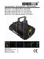 1
1
-
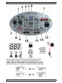 2
2
-
 3
3
-
 4
4
-
 5
5
-
 6
6
-
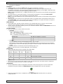 7
7
-
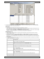 8
8
-
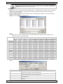 9
9
-
 10
10
-
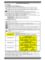 11
11
-
 12
12
-
 13
13
-
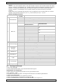 14
14
-
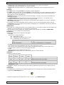 15
15
-
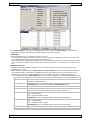 16
16
-
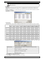 17
17
-
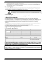 18
18
-
 19
19
-
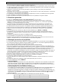 20
20
-
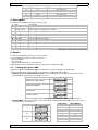 21
21
-
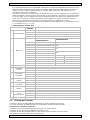 22
22
-
 23
23
-
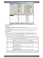 24
24
-
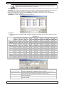 25
25
-
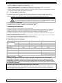 26
26
-
 27
27
-
 28
28
-
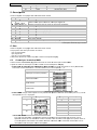 29
29
-
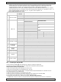 30
30
-
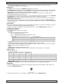 31
31
-
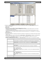 32
32
-
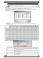 33
33
-
 34
34
-
 35
35
-
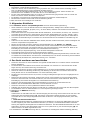 36
36
-
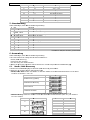 37
37
-
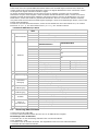 38
38
-
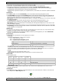 39
39
-
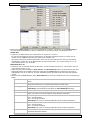 40
40
-
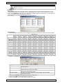 41
41
-
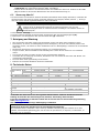 42
42
-
 43
43
-
 44
44
-
 45
45


HQ Power Krystal RGV380 RGV laser projector Manuel utilisateur
- Catégorie
- Stroboscopes
- Taper
- Manuel utilisateur
- Ce manuel convient également à
dans d''autres langues
Documents connexes
-
HQ Power VARNA Manuel utilisateur
-
-
HQ Power VDPL300MR ARUZO Manuel utilisateur
-
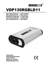 HQ Power VDP130RGBLD11 Manuel utilisateur
-
 HQ Power VDP1401RGLD5 Manuel utilisateur
-
 HQ Power VDL160LL Manuel utilisateur
-
 HQ Power VDL301GL Manuel utilisateur
-
 HQ Power Mini red laser 100mW Manuel utilisateur
-
 HQ Power VDL150GML Manuel utilisateur


Autres documents
-
Cameo LUKE 700 RGB Manuel utilisateur
-
RTI NEO ONE Manuel utilisateur
-
Briteq BT-LASER1500 RGB Le manuel du propriétaire
-
-
 Ibiza Light IBIZA500 Le manuel du propriétaire
-
Chauvet Scan 300 RGB EU Manuel utilisateur
-
-
-
Ibiza Light SCAN500RGB Le manuel du propriétaire
-
Nicols X-line 5K RGB Le manuel du propriétaire
