
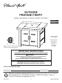
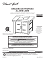
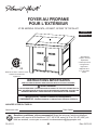
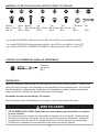
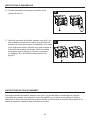
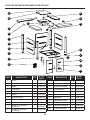
OUTDOOR
PROPANE FIREPIT
MODEL #OFG418TA, OFG900T, OFG901T, OFG444T
Français p. 65
*Propane cylinders
sold separately.
Item may have a
slightly different
appearance
depending on
the model #
purchased.
*
Serial Number
Purchase Date
ATTACH YOUR RECEIPT HERE
130-10-111 Rev. 05/10/18
Español p. 33
C US
ANS Z21.97-2014
•
CSA 2.41-2014
Outdoor Decorative Gas Appliance
Questions, problems, missing parts? Before returning to your retailer, call our customer
service department at 1-877-447-4768, 8:30AM – 4:30PM CST, Monday – Friday, or
e-mail us at [email protected]
INSTALLER: Leave this manual with the consumer.
CONSUMER: Retain this manual for future reference.
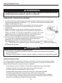
WARNING
IF THE INFORMATION IN THIS MANUAL IS NOT FOLLOWED EXACTLY,
AN ELECTRICAL SHOCK OR FIRE MAY RESULT
CAUSING PROPERTY DAMAGE, PERSONAL INJURY OR LOSS OF LIFE.
IMPORTANT INSTRUCTIONS
PLEASE READ THIS MANUAL BEFORE INSTALLING AND USING APPLIANCE

2
TABLE OF CONTENTS
Safety Information .................................................................................................................. 4
Package Contents .................................................................................................................. 7
Preparation ............................................................................................................................11
Assembly Instructions ............................................................................................................................. 12
Operating Instructions .......................................................................................................... 19
Care and Maintenance ......................................................................................................... 25
Warranty ............................................................................................................................... 26
Troubleshooting .................................................................................................................... 27
Replacement Parts List ........................................................................................................ 28
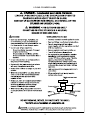
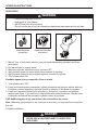
DANGER:
If you smell gas:
1. Shut off gas to the appliance.
2. Extinguish any open ame.
3. If odor continues, keep away from the
appliance and immediately call your
gas supplier or your re department.
WARNING:
Do not store or use gasoline or other
ammable vapors or liquids in the
vicinity of this or any other appliance.
An LP cylinder not connected for use
shall not be stored in the vicinity of this
or any other appliance.
WARNING: For Outdoor Use Only.
DANGER
CARBON MONOXIDE HAZARD
This appliance can produce carbon monoxide which
has no odor.
Using it in an enclosed space can kill you.
Never use this appliance in an enclosed space such
as a camper, tent, car or house.
WARNING: Improper installation, adjustment, alteration,
service or maintenance can cause injury or property damage.
Refer to the owner’s information manual provided with this
appliance. For assistance or additional information consult a
qualied installer, service agency or the gas supplier.

3
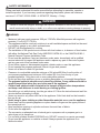
ANSI Z21.97-2014 • CSA 2.41-2014
Outdoor decorative gas appliances
March 2014
© 2014 CSA Group
45
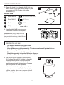
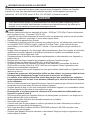
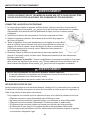
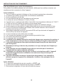
Figure 1
LP-Gas Cylinder Label
(See Clause 4.18.2.)
DANGER
•
FLAMMABLE GAS UNDER PRESSURE.
LEAKING LP-GAS MAY CAUSE A FIRE OR EXPLOSION IF IGNITED
CAUSING SERIOUS BODILY INJURY OR DEATH.
CONTACT LP GAS SUPPLIER FOR REPAIRS, OR DISPOSAL OF THIS
CYLINDER OR UNUSED LP-GAS.
WARNING
• FOR OUTDOOR USE ONLY.*
DO NOT USE OR STORE CYLINDER IN A BUILDING,
GARAGE OR ENCLOSED AREA.
WARNING:
Know the odor of LP-gas. If you hear, see
or smell leaking LP-gas, immediately get
everyone away from the cylinder and call the
Fire Department. Do not aκempt repairs.
CauΩon your LP-gas supplier to:
Be certain cylinder is purged of trapped
air prior to first filling.
Be certain not to over fill the cylinder.
Be certain cylinder requalificaΩon date is
checked.
LP-gas is heavier than air and may seκle in
low places while dissipaΩng.
Contact with the liquid contents of cylinder
will cause freeze burns to the skin.
Do not allow children to tamper or play with
cylinder.
When not connected for use, keep cylinder
valve turned o�. Self contained appliances
shall be limited to a cylinder of 30 lb
capacity or less.
Do not use, store or transport cylinder where
it would be exposed to high temperatures.
Relief valve may open allowing a large
amount of flammable gas to escape.
When transporΩng, keep cylinder secured in
an upright posiΩon with cylinder valve turned
o�.
WHEN CONNECTING FOR USE:
Consult manufacturer’s instrucΩons
concerning the cylinder connecΩon provided
with your appliance.
Be sure regulator vent is not poinΩng up.
Turn o� all valves on the appliance.
Do not check for gas leaks with a match or
open flame. Apply soapy water at areas
marked “X”. Open cylinder valve. If bubble
appears, close valve and have LP-gas
service person make needed repairs. Also,
check appliance valves and connecΩons to
make sure they do not leak before lighΩng
appliance.
Light appliance(s) following manufacturer’s
instrucΩons.
When appliance is not in use, keep the
cylinder valve closed.
Cylinder
Pressure relief valve
Point of connecΩon
Cylinder valve hand wheel
Liquid level indicator
(opΩonal)
DO NOT REMOVE, DEFACE, OR OBLITERATE THIS LABEL
*EXCEPT AS AUTHORIZED BY ANSI/NFPA 58.
DANGER.
Do not store a spare LP cylinder under or near a barbecue grill, or other heat sources.
NEVER fill an LP cylinder beyond 80% full: a fire causing death or serious injury may occur.
Use only in compliance with applicable codes.
Read and follow manufacturer’s instrucΩons.
LP-GAS CYLINDER LABEL

4
SAFETY INFORMATION
Please read and understand this entire manual before attempting to assemble, operate or
install the product. If you have any questions regarding the product, please call customer
service at 1-877-447-4768 8:30AM – 4:30PM CST, Monday – Friday.
DANGER
• Failure to follow the dangers, warnings and cautions contained in this owner’s manual may
result in serious bodily injury or death, or in a re or an explosion causing damage to property.
WARNING
• Maximum inlet gas supply pressure: 250 psi/ 1750 kPa. Manifold pressure with regulator
provided: 11 inch W.C/ 2.74 kPa.
• This appliance shall be used only outdoors in a well-ventilated space and shall not be used
in a building, garage or any other enclosed area.
• DO NOT use this appliance for cooking
• The installation of this product must conform with local codes or, in absence of local codes,
with either the National Fuel Gas Code, ANSIZ223.1/NFPA 54, or the CAN/CGA-B149.1,
Natural Gas and Propane Installation Code.
• Do not use this appliance if any part has been under water. Immediately call a qualied
service technician to inspect the appliance and to replace any part of the control system
and any gas control that has been under water.
• Do not store a spare or disconnected propane cylinder under or near this appliance.
• Do not operate the propane appliance if there is a gas leak present.
• Never use a ame to check for gas leaks.
• Clearance to combustible materials minimum of 24 inches/60.96cm from the sides of
your propane appliance and minimum of 60 inches/152.4 cm from the top of your
propane appliance. Only place unit on non-combustible surfaces.
• Do not put any other appliance cover or anything ammable on, or beneath the appliance.
• The propane appliance should never be used by children. Young children should be
carefully supervised when they are in the area of the appliance.
• Children and adults should be alerted to the hazards of high surface temperatures
and keep a safe distance to avoid burning or clothing ignition.
• Should re go out while burning, turn the gas valve off. Follow the instructions and wait ve
minutes before attempting to relight.
• Never use wood or any other solid fuel in the appliance. Solid fuels shall not be burned in
this gas re pit.
• Never hang or place clothing or other ammable materials on or near the appliance.
• Never lean over the operating appliance or place hands or ngers on the upper portion of
the operational unit.
• Keep ventilation openings in cylinder enclosure free and clear of debris.
• Do not alter the appliance.
• The conversion or attempted use of natural gas in a propane unit or propane gas in a
natural gas unit is dangerous.
• For use with cylinders marked PROPANE only. DO NOT connect to a remote gas supply.
• Do not use this appliance on vehicles or boats. Always operate the appliance on a
at/level surface.

5
SAFETY INFORMATION
WARNING
• Keep any electrical supply cord and fuel supply hose away from any heated surfaces.
• Keep your appliance free and clear from combustible materials, gasoline and other
ammable vapors and liquids.
• Visually inspect burner for obstructions. Keep tank enclosure free and clear from debris.
• Do not use this appliance unless all parts are in place.
• Any guard or other protective device removed for servicing the appliance must be
replaced prior to operating the appliance.
• The hose assembly must be replaced prior to the appliance being put into operation
if there is evidence of excessive abrasion or wear or if the hose is damaged. The
replacement hose assembly shall be specied by the manufacturer.
• Installation and repair should be done by a qualied service person. The appliance
should be inspected before use and at least annually by a qualied service person.
More frequent cleaning may be required as necessary. It is imperative that control
compartment, burners and circulating air passageways of the appliance be
kept clean.
• The propane gas supply cylinder to be used must be constructed and marked in
accordance with the Specications for LP Gas Cylinders of the U.S. Department of
Transportation (D.O.T.) or the National Standard of Canada, CAN/CSA-B339, Cylinders,
Spheres and Tubes for Transportation of Dangerous Goods; and Commission, as
applicable; and provided with a listed overlling prevention device.
• Use only 20-pound cylinders (approximately 18 ¼ inches high and 12 ¼ inches in
diameter) equipped with a cylinder connection device compatible with the connection
for the hose regulator supplied with this appliance. The cylinder must include a collar to
protect the cylinder valve. The gas cylinder should not be dropped or handled roughly!
• Cylinders must be stored outdoors in a well-ventilated area out of the reach of children.
• Disconnect the cylinder when the appliance is not being used.
• Disconnected cylinders must have valve caps tightly installed and must not be stored in
building or any other enclosed area.
• Do not use this appliance under umbrellas, awnings, etc.
• Only use the appliance on stable surfaces.
• Do not operate with a vinyl or PVC cover.
• Allow the unit to cool before placing a vinyl or PVC cover on the unit.
• Do not sit on unit.
• Never use charcoal or lighter uid with the re pit.
• Do not use gasoline, kerosene or alcohol for lighting.
• Never keep a lled LP cylinder in a hot car or car trunk. Heat will cause the gas pressure
to increase, which may open the relief valve and allow gas to escape.
• Do not lean over re pit when lighting. Read instructions before lighting.
• If the ame extinguishes accidentally during ignition or operation, immediately TURN OFF
the cylinder valve and then TURN OFF the control knob.

6
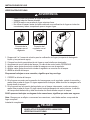
CAUTION
GLASS ROCKS
1. Do not light or use gas unit if glass rocks are wet. Make sure glass rocks are completely dry
before lighting as intense heat could cause the rock to crack.
2. Glass rocks could hit a person’s face or eyes during the initial startup of this unit. Keep away
from the appliance for the rst 20 minutes after lighting.
3. Use only Pleasant Hearth / GHP Group, Inc. factory-authorized glass rocks. The use of any
glass rock that is not factory-authorized can be dangerous and will void your warranty.
F
WARNING
FOR PROPANE GAS UNITS
• The gas pressure regulator provided with the propane appliance must be used.
• The replacement pressure regulator must be those specied by the appliance manufacturer.
• Do not attempt to disconnect the gas cylinder or any gas tting while your appliance is in
operation.
• A dented or rusty propane cylinder may be hazardous and should be checked by your gas
supplier prior to use.
• Do not use a propane cylinder with a damaged valve and any other worn out parts.
• Transit and store the empty gas cylinders carefully and properly.
• If you see, smell or hear the hiss of escaping gas from the propane cylinder:
1. Disconnect propane gas cylinder
2. Do not attempt to correct the problem yourself.
3. Get to your gas supplier and/or the re department for help.
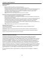
SAFETY INFORMATION
This product and the fuels used to operate this product (liquid propane or natural gas), and the
products of combustion of such fuels, can expose you to chemicals including benzene, which is
known to the State of California to cause cancer and reproductive harm.
For more information go to: www.P65warnings.ca.gov
WARNING

7
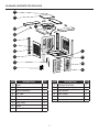
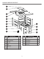
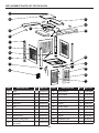
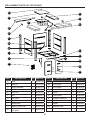
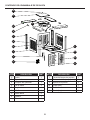
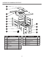
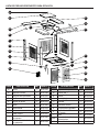
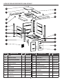
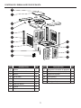
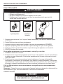
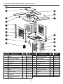
PACKAGE CONTENTS FOR OFG418TA
PART DESCRIPTION QTY.
A Knob 1
B Table Lid 1
C Burner Assembly 1
D 1/4 Table 4
E Angle Iron 4
F Post 4
G Side Panel 3
H Chain 1
I Bottom Plate 1
PART DESCRIPTION QTY.
J Propane Tank Strap 1
K Glass Rocks (one pack) 1
L Door Bracket 1
M Door (Right) 1
N Knob 2
O Door (Left) 1
A
B
C
D
E
F
G
H
I
J
K
L
M
N
O

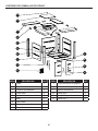
8
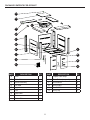
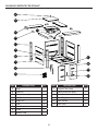
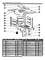
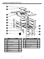
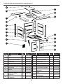
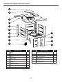
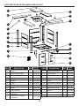
PART DESCRIPTION QTY.
A Knob 1
B Table Lid 1
C Burner Assembly 1
D 1/4 Table 4
E Angle Iron 4
F Post 4
G Side Panel 3
H Chain 1
I Bottom Plate 1
PART DESCRIPTION QTY.
J Propane Tank Strap 1
K Glass Rocks (one pack) 1
L Door Bracket 1
M Door (Right) 1
N Door Handle 2
O Door (Left) 1
PACKAGE CONTENTS FOR OFG900T
A
B
C
D
E
F
G
H
I
J
K
L
M
N
O

9
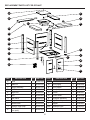
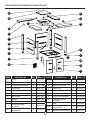
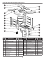
PACKAGE CONTENTS FOR OFG901T
PART DESCRIPTION QTY.
A Knob 1
B Table Lid 1
C Burner Assembly 1
D 1/4 Table 4
E Angle Iron 4
F Post 4
G Side Panel 3
H Chain 1
I Bottom Plate 1
PART DESCRIPTION QTY.
J Propane Tank Strap 1
K Glass Rocks (one pack) 1
L Door Bracket 1
M Door (Right) 1
N Door Handle 2
O Door (Left) 1
A
B
C
D
E
F
G
H
I
J
K
L
M
N
O

10
PACKAGE CONTENTS FOR OFG444T
PART DESCRIPTION QTY.
A Knob 1
B Table Lid 1
C Burner Assembly 1
D 1/4 Table 4
E Angle Iron 4
F Post 4
G Side Panel 3
H Chain 1
I Bottom Plate 1
PART DESCRIPTION QTY.
J Propane Tank Strap 1
K Glass Rocks (one pack) 1
L Door Bracket 1
M Door (Right) 1
N Door Handle 2
O Door (Left) 1
A
B
C
D
E
F
G
H
I
J
K
L
M
N
O

11
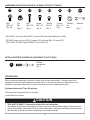
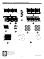
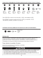
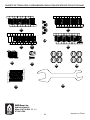
HARDWARE USED (FOR OFG418TA, OFG900T, OFG901T, OFG444T)
PREPARATION
Before beginning assembly of product, make sure all parts are present. Compare parts with
package contents list and hardware contents above. If any part is missing or damaged, do not
attempt to assemble the product. Contact customer service for replacement parts.
Estimated Assembly Time: 60 minutes
Tools required for assembly (not included):
Leak Detection Solution.
EE
*Screw
M4 X 6
Qty. 5
CC
Bolt
M6 X 30
Qty. 4
BB
Nut
M6
Qty. 8
AA
Bolt
M6 X 12
Qty. 38
DD
Screw
M5 X 12
Qty. 4
FF
HH
Wrench
Qty. 1
CAUTION
THIS UNIT IS HEAVY. Two people required for safe assembly.
Two people required for safe assembly. Some parts may contain sharp edges. Wear protective
gloves if necessary. Read and follow all safety statements, warnings, assembly instructions and
use and care instructions before attempting to assemble and use.
Phillips
screwdriver
Qty. 1
II
EXTRA CONTENTS (PACKED IN A SEPARATE PLASTIC BAG)
GG
*Screw
M4 X 10
Qty. 1
*Washer
ø4
Qty.5
* OFG418TA uses only three M4 X 6 screws (EE) and three Washers ø4 (GG).
* OFG444T uses only four M4 X 6 screws (EE) and one M4 x 10 screw (FF).
OFG418TA, OFG900T and OFG901T do not use (FF).

12
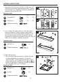
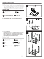
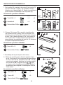
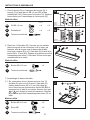
ASSEMBLY INSTRUCTIONS
1. Attach the knob (N) or door handle (N) to the door (O)
with M4X6 screws (EE) and washers ø4 (GG). Tighten
with screwdriver (II). Repeat procedure to complete the
assembly of the other door (M).
Hardware Used
2. Turn 1/4 table (D) upside down on a soft, at surface
such as a blanket or carpet to ensure that the table
top surface does not scratch. Attach an angle iron (E)
to a 1/4 table (D) with one M6X12 bolt (AA). Repeat
procedure to complete the assembly of the rest of the 1/4
tables. Do not tighten completely at this time.
1a
1b
D
2
C
II
II
GG
EE
Washer ø4
Screw M4 X 6
Phillips screwdriver
Phillips screwdriver
OFG900T
OFG901T
OFG444T
use handles
OFG418TA
uses knobs
AA
DD
Bolt M6 X 12
X 4
Hardware Used
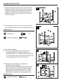
3. Table Top Assembly:
3-1. On soft surface, line up holes in a 1/4 table (D) with
corresponding holes from another 1/4 table (D).
Insert two M6 X 12 bolts (AA) through holes. Finger
tighten with two M6 nuts (BB). Be sure
1
and
2
are
level, and fully tighten. Repeat procedure to complete
the assembly of the rest of 1/4 tables.
II
Phillips screwdriver
AA
BB
Bolt M6 X 12
Nut M6
X 8
X 8
Hardware Used
M
O
O
O
O
N
M
N
GG
GG
EE
EE
AA
D
E
OFG900T, OFG901T,
OFG444T
OFG418TA
X 4 X 2
X 4 X 2
AA
D
3-1
1
2
CC
DD
C
D
BB
AA
1
2
AA BB

13
BB
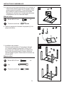
ASSEMBLY INSTRUCTIONS
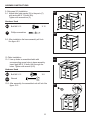
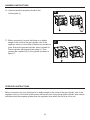
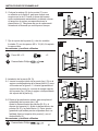
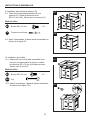
4. Attach propane tank strap (J) to bottom plate (I).
5. Post Installation
Attach four posts (F) to the bottom plate (I) with four
M6 X 30 bolts (CC). The tank hole on the bottom
plate (I) should be in the front as pictured. Tighten
with screwdriver (II) and wrench (HH).
4
L
5-1
F
I
HG
Q
CC
Bolt M6 X 30 X 4
HH
Wrench
Hardware Used
II
Phillips screwdriver
II
Phillips screwdriver
AA
Bolt M6 X 12 X 4
3-2. Once the four panels are connected with two bolts
per connection point, use four more M6 x 12 bolts (AA)
to secure the edges at four points around the table.
Tighten the loose bolts from step two completely.
Hardware Used
5
J
I
I
CC
F
3-2
AA

14
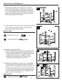
8. Door (M,O) installation
8-1. Insert the bottom peg of door (left) (O) to the
corresponding hole of the bottom plate (I) as
illustrated in gure 8-1. Slightly lift the door bracket
(L) and insert the top peg of the door (left) (O) to the
corresponding hole of the door bracket (L).
8-1
ASSEMBLY INSTRUCTIONS
6. Hang the chain (H) from the posts (F) as illustrated
in gure 6 so that it connects from corner to corner.
When the re table is fully assembled, the tank will
be placed in the tank hole on the bottom plate (I).
Make sure that the chain is positioned so that it will
not block the tank.
4
L
Q
6
8-2 Repeat above procedure to complete the
assembly of door (right) (M).
Adjust the distance between the doors (M, O) and
the door bracket (L). Adjust the distance between
the doors (M, O) and the bottom plate (I). These
adjustments ensure both doors can open easily.
Tighten the door bracket (L) with screwdriver (II).
8-2
F
H
O
O
F
Hardware Used
Hardware Used
7. Attach the door bracket (L) to the two front posts (F)
with two M6X12 bolts (AA). Do not tighten the bolts yet.
6
E
AA
Bolt M6 X 12 X 2
II
II
Phillips screwdriver
Phillips screwdriver
DD
7
AA
F
L
L
L
I
I
M
TOP PEG
BOTTOM PEG
I

15
10
ASSEMBLY INSTRUCTIONS
AA
Bolt M6 X 12 X 8
10-1
AA
10-2
Hardware Used
9. Side panel (G) Installation.
9-1. Attach three side panels (G) to the posts (F)
with twelve M6 X 12 bolts (AA).
Tighten with screwdriver (II).
10. Table Installation
10-1. Line up holes in assembled table with
corresponding screw holes in base assembly.
Insert eight M6 X 12 bolts (AA) through the
holes. Tighten with wrench (HH).
DD
9-1
9-2
AA
Bolt M6 X 12
X 12
Hardware Used
9-2. After installation the base assembly will look
like gure 9-2.
10-2. After assembly, the assembled unit will look like
gure 10-2.
G
F
AA
II
Phillips screwdriver
HH
Wrench

16
ASSEMBLY INSTRUCTIONS
Hardware Used
11. Burner Assembly Installation
11-1. Make sure the control knob faces the front side
of the unit where the doors are located. Line up
holes in the burner assembly (C) with screw
holes on the table. Insert four M5X12 screws
(DD) through the holes. Fasten with
screwdriver (II).
11-2. The assembled unit will look like gure 11-2.
11-2
11-1
DD
Screw M5 X 12 X 4
II
Phillips screwdriver
DD
C
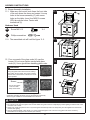
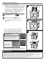
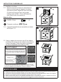
12. Pour one pack of the glass rocks (K) over the
burner. Do not cover ignition screen with glass
rocks (K). Use a glove when handling glass rocks.
12
A
P
The burner of the rebowl must be covered by glass rocks
completely. Otherwise the ame may be extinguished occasionally.
See the Figure CORRECT and INCORRECT for reference.
CORRECT
INCORRECT
Screen
Do not place glass
rocks on screen.
Keep screen clear.
K
P
CAUTION
GLASS ROCKS - Use a glove when handling glass rocks.
1. Do not light or use gas unit if glass rocks are wet. Make sure glass rocks are completely dry before lighting as intense heat could
cause the rock to crack.
2. Glass rocks could hit a person’s face or eyes during the initial startup of this unit. Keep away from the appliance for the rst 20
minutes after lighting.
3. Use only Pleasant Hearth / GHP Group, Inc. factory-authorized glass rocks. The use of any glass rock that is not factory-
authorized can be dangerous and will void your warranty.
WARNING
DO NOT COVER THE IGNITION SCREEN when
placing the glass rocks into the re bowl. Always
keep Ignition Screen visible. This screen must be
clear and free of obstructions at all times to insure
proper operation.

17
ASSEMBLY INSTRUCTIONS
Caution: Never place a table lid on the
re pit when in use. Ensure the re pit
has cooled before placing a table lid over
the re pit.
13. Screw the knob (A) on the table lid (B) with one
M4X6 screw (EE) or one M4X10 screw (FF) and
one washer ø4 (GG). Tighten with phillips
screwdriver (II).
15. Use only 20-pound cylinders (approximately
18 ¼ inches high and 12 ¼ inches in diameter)
equipped with a cylinder connection device
compatible with the connection for the hose
regulator supplied with this appliance. Propane
gas and cylinder are sold separately.
A dented, rusted or damaged propane cylinder
may be hazardous and should be checked by your
cylinder supplier. Never use a propane cylinder
with a damaged valve connection.
15
Standard 20 lb. tank
Use a glove when handling glass rocks.
Do not sit or stand on this table.
Keep children away during assembly. This item contains small parts which can
be swallowed by children.
Do not use indoors and inside any enclosure.
Retain the assembly instruction for future reference.
Installer — Please leave these instructions with the owner.
14. Place the table lid (B) over the re pit.
Total re pit installation is complete.
14
10-2
13
GG
EE
B
A
Hardware Used
FF
GG
EE
Screw M4 X 10
Washer ø4
Screw M4 X 6
X 1 (OFG444T)
X 1 (OFG418TA, OFG900T, OFG901T)
X 1
ATTENTION: THIS PRODUCT IS NOT FOR COMMERCIAL USE. INTENDED FOR
RESIDENTIAL USE ONLY.
II
Phillips screwdriver

18
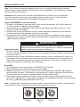
The propane cylinder must be constructed and marked in accordance with the specications for LP
gas cylinders of the U.S. Department of Transportation (DOT) or the standard for cylinders, spheres
and tubes for transportation of dangerous goods and commission, CAN/CSA-B339.
The cylinder must have a listed overlling prevention device.
The cylinder must have a connection device compatible with the connection for the appliance.
Never connect an unregulated propane cylinder to this appliance.
The cylinder must include a collar to protect the cylinder valve. The gas cylinder should not be
dropped or handled roughly.
The LP-gas supply cylinder must be disconnected when this appliance is not in use. Storage of
an appliance indoors is permissible ONLY if the cylinder is disconnected and removed from the
appliance. Cylinders must be stored outdoors out of the reach of children and must not be stored in a
building, garage or any other enclosed area. Your cylinder must never be stored where temperatures
can reach over 125°F / 51.5°C.
The maximum inlet gas supply pressure: 250 psi /1750 kPa. The minimum inlet gas supply pressure:
5 psi /35kPa.
Place a dust cap on cylinder valve outlet whenever the cylinder is not in use. Only install the type of
dust cap on the cylinder valve outlet that is provided with the cylinder valve. Other types of caps or
plugs may result in leakage of propane.
DO NOT obstruct the ow of combustion air and ventilation air to the re pit.
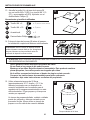
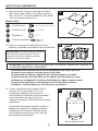
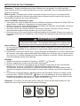
The propane cylinder must be arranged for vapor withdrawal and equipped with a listed overlling
prevention device. Please use the proper cylinder orientation to provide vapor withdrawal.
NOTE: The cylinder must be fully upright for the cylinder to have vapor withdrawal only.
ASSEMBLY INSTRUCTIONS
CAUTION
a. Do not store a spare LP-gas cylinder under or near this appliance.
b. Never ll the cylinder beyond 80 percent full.
c. If the information in (a) and (b) is not followed exactly, a re causing death or serious injury
may occur.
The pressure regulator and hose assembly supplied with the appliance must be used. The installation
must conform with local codes, or in the absence of local codes, with national fuel gas code, ANSI
A223.1/NFPA54, natural gas and propane Installation Code, CSA B149.1, or propane storage and
handling code, B149.2.
CORRECT
WRONG
WRONG
CORRECT WRONG WRONG

19
ASSEMBLY INSTRUCTIONS
16. Seat and position propane cylinder in the
bottom plate (I).
16
17. Before connection, be sure that there is no debris
caught in the outlet of the gas cylinder, inlet of the
regulator valve or in the outlet of the burner and burner
ports. Ensure the propane cylinder valve is turned off.
Fasten cylinder with propane tank strap (J). Then
connect the regulator (R) to the cylinder as shown in
gure 17.
17
J
R
I
Before connection, be sure that there is no debris caught in the outlet of the gas cylinder, inlet of the
regulator valve or in the outlet of the burner and burner ports. Keep the propane cylinder valve closed
and disconnect the propane cylinder from the regulator valve when the re pit is not in use.
OPERATION INSTRUCTIONS

20
OPERATION INSTRUCTIONS
ARNING
WARNING
In the connection process, make sure:
• the regulator inlet connector mates with the cylinder valve outlet properly, safely and rmly, and;
• the LP gas hose does not come in contact or remain in contact with the burner assembly.
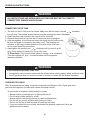
CHECKING FOR LEAKS
After all connections are made, check all connections and ttings on the LP gas tank valve,
gas hose and regulator for leaks with a water and soap solution.
To prevent re or explosion while testing for a leak:
• Always perform a leak test prior to lighting the re pit.
• Do not smoke while testing for a leak.
• Always perform leak tests outdoors in a well-ventilated area.
• Do not use any source of ame while testing for leaks.
• Do not use the re pit until any and all leaks are corrected.
• If you are unable to correct a leak, disconnect the propane supply and call a gas
appliance service dealer.
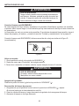
CONNECTING THE LP TANK
1. The knob on the LP tank must be closed. Make sure that the knob is turned clockwise
to a full stop. The cylinder supply system must be arranged for vapor withdrawal.
2. Check that the control knob on the control unit is turned off.
3. Remove the protective cap from the LP tank valve and coupling nut.
4. Hold the regulator in one hand and insert the nipple into the valve outlet.
Be sure the nipple is centered in the valve outlet. The coupling nut
connects to the large outside threads on the valve outlet. Use care –
do not cross thread the connection.
5. Hand-tighten the coupling nut clockwise until it comes to a full
stop. Firmly tighten by hand only. Do not use tools.
To Disconnect: Fully close the tank valve by turning clockwise.
Turn the coupling nut counterclockwise until the regulator
assembly detaches.
WARNING
ALL INSTRUCTIONS AND SAFEGUARDS ON THIS PAGE MUST BE FOLLOWED TO
PREVENT FIRE, DAMAGE AND/OR INJURY.
La page est en cours de chargement...
La page est en cours de chargement...
La page est en cours de chargement...
La page est en cours de chargement...
La page est en cours de chargement...
La page est en cours de chargement...
La page est en cours de chargement...
La page est en cours de chargement...
La page est en cours de chargement...
La page est en cours de chargement...
La page est en cours de chargement...
La page est en cours de chargement...
La page est en cours de chargement...
La page est en cours de chargement...
La page est en cours de chargement...
La page est en cours de chargement...
La page est en cours de chargement...
La page est en cours de chargement...
La page est en cours de chargement...
La page est en cours de chargement...
La page est en cours de chargement...
La page est en cours de chargement...
La page est en cours de chargement...
La page est en cours de chargement...
La page est en cours de chargement...
La page est en cours de chargement...
La page est en cours de chargement...
La page est en cours de chargement...
La page est en cours de chargement...
La page est en cours de chargement...
La page est en cours de chargement...
La page est en cours de chargement...
La page est en cours de chargement...
La page est en cours de chargement...
La page est en cours de chargement...
La page est en cours de chargement...
La page est en cours de chargement...
La page est en cours de chargement...
La page est en cours de chargement...
La page est en cours de chargement...
La page est en cours de chargement...
La page est en cours de chargement...
La page est en cours de chargement...
La page est en cours de chargement...
La page est en cours de chargement...
La page est en cours de chargement...
La page est en cours de chargement...
La page est en cours de chargement...
La page est en cours de chargement...
La page est en cours de chargement...
La page est en cours de chargement...
La page est en cours de chargement...
La page est en cours de chargement...
La page est en cours de chargement...
La page est en cours de chargement...
La page est en cours de chargement...
La page est en cours de chargement...
La page est en cours de chargement...
La page est en cours de chargement...
La page est en cours de chargement...
La page est en cours de chargement...
La page est en cours de chargement...
La page est en cours de chargement...
La page est en cours de chargement...
La page est en cours de chargement...
La page est en cours de chargement...
La page est en cours de chargement...
La page est en cours de chargement...
La page est en cours de chargement...
La page est en cours de chargement...
La page est en cours de chargement...
La page est en cours de chargement...
La page est en cours de chargement...
La page est en cours de chargement...
La page est en cours de chargement...
La page est en cours de chargement...
-
 1
1
-
 2
2
-
 3
3
-
 4
4
-
 5
5
-
 6
6
-
 7
7
-
 8
8
-
 9
9
-
 10
10
-
 11
11
-
 12
12
-
 13
13
-
 14
14
-
 15
15
-
 16
16
-
 17
17
-
 18
18
-
 19
19
-
 20
20
-
 21
21
-
 22
22
-
 23
23
-
 24
24
-
 25
25
-
 26
26
-
 27
27
-
 28
28
-
 29
29
-
 30
30
-
 31
31
-
 32
32
-
 33
33
-
 34
34
-
 35
35
-
 36
36
-
 37
37
-
 38
38
-
 39
39
-
 40
40
-
 41
41
-
 42
42
-
 43
43
-
 44
44
-
 45
45
-
 46
46
-
 47
47
-
 48
48
-
 49
49
-
 50
50
-
 51
51
-
 52
52
-
 53
53
-
 54
54
-
 55
55
-
 56
56
-
 57
57
-
 58
58
-
 59
59
-
 60
60
-
 61
61
-
 62
62
-
 63
63
-
 64
64
-
 65
65
-
 66
66
-
 67
67
-
 68
68
-
 69
69
-
 70
70
-
 71
71
-
 72
72
-
 73
73
-
 74
74
-
 75
75
-
 76
76
-
 77
77
-
 78
78
-
 79
79
-
 80
80
-
 81
81
-
 82
82
-
 83
83
-
 84
84
-
 85
85
-
 86
86
-
 87
87
-
 88
88
-
 89
89
-
 90
90
-
 91
91
-
 92
92
-
 93
93
-
 94
94
-
 95
95
-
 96
96


Pleasant Hearth OFG418TA Manuel utilisateur
- Taper
- Manuel utilisateur
dans d''autres langues
Documents connexes
Autres documents
-
 Red Mountain Valley 8922643 Le manuel du propriétaire
-
Cosco 88-533DBTE Manuel utilisateur
-
Endless Summer GAD15310ES Le manuel du propriétaire
-
Camp Chef FP30 Manuel utilisateur
-
Endless Summer GAD19102ES Le manuel du propriétaire
-
-
BLUE SKY TT22SQ Le manuel du propriétaire
-
