John Deere Saw ET-3409-J Manuel utilisateur
- Catégorie
- Outils électroportatifs
- Taper
- Manuel utilisateur
Ce manuel convient également à

Table Saw Operator's Manual 1
CAUTION
RISK OF INJURY!
READ MANUAL BEFORE OPERATING!
THIS MANUAL IS AN IMPORTANT PART OF THE TABLE SAW
AND SHOULD REMAIN WITH THIS UNIT WHEN YOU SELL OR RENT IT.
ET-3409-J
TABLE SAW

2 Table Saw Operator's Manual
Congratulations on the purchase of your new Table Saw! You can be assured your table saw was constructed and
designed with quality and performance in mind. Each component has been rigorously tested to ensure the highest
level of acceptance.
This operator's manual was compiled for your benefit. By reading and following the simple safety, installation, opera-
tion, maintenance and troubleshooting steps described in this manual, you will receive years of trouble-free operation
from your new tool. The contents of this manual are based on the latest product information available at the time of
publication. The manufacturer reserves the right to make changes in price, color, materials, equipment, specifications
or models at any time without notice.
Once the unit has been removed from the box, immediately write in the serial number of your unit in the space provided
below.
SERIAL NUMBER_________________________________
Inspect for signs of obvious or concealed freight damage. If damage does exist, file a claim with the transportation company
immediately. Be sure that all damaged parts are replaced and that the mechanical problems are corrected prior to operation
of the unit. If you require service, contact your Customer Service.
Mi-T-M
®
Corporation, 8650 Enterprise Drive, Peosta, IA 52068
1-877-JD-KLEEN / (1-877-535-5336) Fax 563-556-1235
Monday - Friday 8:00 a.m. - 5:00 p.m. CST
Please have the following information available for all service calls:
1. Model Number
2. Serial Number
3. Date and Place of Purchase
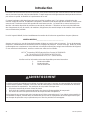
Introduction
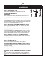
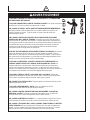
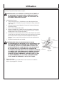
WEAR RESPIRATORY PROTECTION
Some dust created by power sanding, sawing, grinding, drilling and other construction activities contain chemicals
known to the State of California to cause cancer, birth defects or other reproductive harm. Some examples of
these chemicals are:
• Lead from lead-base paints,
• Crystalline Silica from bricks, cement and other masonry products, and
• Arsenic and Chromium from chemically-treated lumber.
Your risk from these exposures varies, depending on how often you do this type of work. To reduce your exposure
to these chemicals, work in a well ventilated area and work with approved safety equipment, such as those dust
masks that are specially designed to filter out microscopic particles.
WARNING

Table Saw Operator's Manual 3
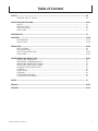
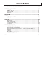
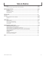
Table of Content
SAFETY ....................................................................................................................................................... 4-9
GENERAL SAFETY RULES............................................................................................................ 4-9
FUNCTIONAL DESCRIPTION..................................................................................................................... 10-11
MODEL............................................................................................................................................ 10
NAME OF PARTS ........................................................................................................................... 10
SPECIFICATIONS........................................................................................................................... 11
UNPACKING ................................................................................................................................... 11
PREPARATION ........................................................................................................................................... 12
ASSEMBLY ................................................................................................................................................. 13-18
PROCEDURES ............................................................................................................................... 13-15
ADJUSTMENT ................................................................................................................................ 15-18
OPERATION ................................................................................................................................................ 18-24
APPLICATIONS .............................................................................................................................. 18
PRE-OPERATION........................................................................................................................... 18
PRACTICAL OPERATIONS ............................................................................................................ 19-20
OPERATION ................................................................................................................................... 20-24
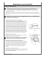
MAINTENANCE AND INSPECTION............................................................................................................ 25-26
INSPECTING SAW BLADE............................................................................................................. 25
INSPECTING CARBON BRUSHES ................................................................................................ 25
INSPECTING MOUNTING SCREWS ............................................................................................. 25
INSPECTING SAW BLADE GUARD............................................................................................... 25
CLEANING SAW BLADE GUARD .................................................................................................. 25
STORAGE....................................................................................................................................... 26
LUBRICATION ................................................................................................................................ 26
CLEANING ...................................................................................................................................... 26
SERVICE AND REPAIRS................................................................................................................ 26
STANDARD ACCESSORIES .......................................................................................................... 26
NOTES......................................................................................................................................................... 27
FRENCH ...................................................................................................................................................... 28-53
SPANISH ..................................................................................................................................................... 54-79

4 Table Saw Operator's Manual
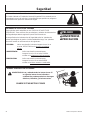
RECOGNIZE SAFETY INFORMATION
This is the safety alert symbol. When you see this symbol on your tool or in
this manual, be alert to the potential for personal injury.
Follow recommended precautions and safe operating practices.
UNDERSTAND SIGNAL WORDS
A "DANGER, WARNING or CAUTION" safety warning will be surrounded by a
"SAFETY ALERT BOX." This box is used to designate and emphasize Safety
Warnings that must be followed when operating this tool.
Accompanying the Safety Warnings are "signal words" which designate the degree
or level of hazard seriousness. The "signal words" used in this manual are as
follows:
DANGER: Indicates an imminently hazardous situation
which, if not avoided, WILL result in death or serious injury.
WARNING:Indicates a potentially hazardous situation
which, if not avoided, COULD result in death or serious injury.
CAUTION: Indicates a potentially hazardous situation
which, if not avoided MAY result in minor or moderate injury.
Safety
GENERAL SAFETY RULES
WARNING: Read and understand all instructions.
Failure to follow all instructions listed below, may
result in electric shock, fire and/or serious personal injury.
SAVE THESE INSTRUCTIONS

Table Saw Operator's Manual 5
ALWAYS KEEP GUARDS IN PLACE and in working order.
ALWAYS KEEP WORK AREA CLEAN
Avoid injuries by not cluttering the work areas and work benches.
NEVER USE TOOL IN HAZARDOUS
ENVIRONMENTS
Never use the power tool in damp or wet places and never expose it to rain.
Always keep the work area well lighted.
NEVER PERMIT CHILDREN OR OTHERS TO LOITER NEAR THE WORK
AREA
Keep all people (especially children) away from the work area. Always unplug
unattended tools and keep the work place tamper-proof by installing locks on the
doors and on the master switches. Always remove the safety key from the switch
and store it in a secure place, when the tool is not in use.
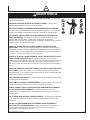
ALWAYS WEAR PROPER APPAREL WHEN WORKING WITH THE TOOL
Never wear loose clothing, gloves, neckties, rings, bracelets or other jewelry
which may get caught in the moving parts. Always wear nonslip footwear,
preferably with steel toes. Wear protective hair covering to contain long hair.
ALWAYS USE EYE PROTECTION WHEN WORKING WITH THE TOOL TO
PREVENT EYE INJURY
Ordinary eyeglasses do not provide adequate protection because they have only
impact resistant lenses, they are NOT safety glasses. Also, use a face mask for
additional safety and wear a dust mask if the cutting operation produces dust.
ALWAYS SECURE THE WORKPIECE TO THE FENCE OR THE TABLE
Use clamps or a vise to hold the workpiece in place. It is safer than using your
hand and it frees both hands to operate the tool.
NEVER OVERREACH
Always keep proper footing and balance when working with the tool.
ALWAYS DISCONNECT THE TOOL
before servicing and before changing blades or other accessories.
NEVER RISK UNINTENTIONAL STARTING WHEN PLUGGING IN THE TOOL
Always confirm that the switch is in the OFF position before inserting the power
plug into the receptacle.
NEVER STAND ON THE TOOL
Serious injury could occur if the tool is tipped or if unintentional contact with the
saw blade is made.
NEVER LEAVE THE TOOL RUNNING WHILE UNATTENDED. TURN POWER
OFF
Do not leave tool until it comes to a complete stop. Always turn the power off
when the tool is not in use. Always unplug the power cord when the tool is not in
use.
WARNING

6 Table Saw Operator's Manual
WARNING
CAUTION
FOR YOUR OWN SAFETY READ THIS INSTRUCTION MANUAL BEFORE OPERATING THE TABLE SAW
1. Always wear eye protection when using the table saw.
2. Always use saw blade guard and spreader for every operation for which it can be used, including all through
sawing.
3. Always keep hands out of the path of the saw blade.
4. Always use a push stick when required.
5. Pay particular attention to instructions on reducing risk of kickback.
6. Never perform any freehand operation with the table saw.
7. Never reach around or over the saw blade.
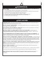
ALWAYS REMOVE ADJUSTING KEYS AND WRENCHES BEFORE STARTING TOOL
Always confirm that all keys and adjusting wrenches have been removed from the tool before it is turned on.
NEVER FORCE THE TOOL
It will do the job better and more safely if it is operated at the rate for which it was designed.
ALWAYS USE THE RIGHT TOOLS
Never force a tool or an attachment to do a job for which it was not designed.
ALWAYS MAINTAIN TOOLS WITH CARE
Always keep tools sharp and clean for the best and safest performance. Always follow instructions for lubricating
the tool and for changing accessories.
ALWAYS USE RECOMMENDED ACCESSORIES ONLY WHEN OPERATING THIS TOOL
Consult this instruction manual for descriptions of recommended accessories. To avoid personal injuries, use only
recommended accessories in conjunction with this tool.
ALWAYS CHECK FOR DAMAGED PARTS BEFORE USING THE TOOL
Always check the guard and all other components for damage before using the tool to assure that they will function
properly. Check all moving parts for proper alignment, free from binding and other conditions that might affect
proper operation. Always repair or replace any damaged guards or other damaged components before using the
tool.
ALWAYS CONFIRM THE ROTATION DIRECTION OF THE BLADE BEFORE USING THE TOOL
Always feed work into the tool against the rotation direction of the blade in order to prevent possible injury.
PROPER GROUNDING
This tool should be grounded while in use to protect the operator from electric shock.
This tool was not designed to be used for mass-production applications and should not be used in mass-produc-
tion environments.
When servicing this tool, use only authorized replacement parts.
Apply 115 volts AC only to this tool. Applying the wrong voltage or applying DC power can cause the POWER
TOOL to operate improperly and cause serious personal injury or damage the tool.

Table Saw Operator's Manual 7
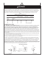
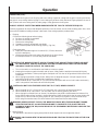
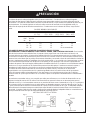
EXTENSION CORD
Make sure your extension cord is in good condition. When using an extension cord, be sure to use one heavy
enough to carry the current your product will draw. An undersized cord will cause a drop in line voltage resulting in
loss of power and overheating. Table shows the correct size to use depending on cord length and nameplate
ampere rating. If in doubt, use the next heavier gage. The smaller the gage number, the heavier the cord.
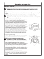
GROUNDING INSTRUCTIONS
ALL GROUNDED, CORD-CONNECTED TOOLS: In the event of a malfunction or breakdown, grounding provides
a path of least resistance for electric current to reduce the risk of electric shock. This tool is equipped with an
electric cord having an equipment-grounding conductor and a grounding plug. The plug must be plugged into a
matching outlet that is properly installed and grounded in accordance with all local codes and ordinances. Do not
modify the plug provided - if it will not fit the outlet, have the proper outlet installed by a qualified electrician. Im-
proper connection of the equipment - grounding conductor can result in a risk of electric shock. The conductor with
insulation having an outer surface that is green with or without yellow stripes is the equipment grounding conductor.
If repair or replacement of the electric cord or plug is necessary, do not connect the equipment-grounding conductor
to a live terminal.
Check with a qualified electrician or service personnel if the grounding instructions are not completely understood,
or if it doubt as to whether the tool is properly grounded.
Use only 3-wire extension cords that have 3-prong grounding plugs and 3-pole receptacles that accept the tool's
plug. Repair or replace damaged or worn cord immediately.
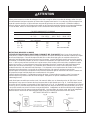
Grounded, cord-connected tools intended for use on a supply circuit having a nominal rating less than 150 volts:
This tool is intended for use on a circuit that has an outlet that looks like the one illustrated in Fig. A. The tool has a
grounding plug that looks like the plug illustrated in Fig. A. A temporary adapter, which looks like the adapter illus-
trated in Fig. B and C, may be used to connect this plug to a 2-pole receptacle as shown in Fig. B if a properly
grounded outlet is not available. The temporary adapter should be used only until a properly grounded outlet can be
installed by a qualified electrician. The green-colored rigid ear, lug, and the like, extending from the adapter must be
connected to a permanent ground such as a properly grounded outlet box.
CAUTION
Table 1
MINIMUM GAGE FOR CORD SETS
Total Length of Code in Feet (Meter)
0-25 26-50 51-100 101-150
(0-7.6) (7.9-15.2) (15.5-30.5) (30.8-45.7)
Ampere Rating AWG Size of Cord
More Not More
Than Than
0 6 18 16 16 14
6 10 18 16 14 12
10 12 16 16 14 12
12 16 14 12 Not recommended

8 Table Saw Operator's Manual
IMPORTANT
SPECIFIC SAFETY RULES FOR USE OF THIS POWER TOOL
WARNING: THE FOLLOWING SPECIFIC OPERATING INSTRUCTIONS MUST BE OBSERVED WHEN
USING THIS POWER TOOL IN ORDER TO AVOID INJURY.
DO's:
ALWAYS OBSERVE THE FOLLOWING RULES TO ASSURE SAFE USE OF THIS TOOL:
1. Review the Manual and familiarize yourself with the safety rules and operatinginstructions for this POWER
TOOL before attempting to use it.
2. Always confirm that the POWER TOOL is clean before using it.
3. Always wear snug-fitting clothing, nonskid footwear (preferably with steel toes) and eye protection when
operating the POWER TOOL.
4. Always handle the POWER TOOL carefully. If the POWER TOOL falls or strikes against a hard object, it might
become deformed or cracked or sustain other damage.
5. Always cease operating the saw at once, if you notice any abnormality what so ever.
6. Always confirm that all components are mounted properly and securely before using the tool.
7. When replacing the saw blade, always confirm that the rating of the new blade is correct for use on this tool.
8. Always shut off the power and wait for the saw blade to completely stop rotating before doing any maintenance
or adjustments.
9. Always make a trial run first before attempting any new use of the saw.
10. Always handle the saw blade with care when dismounting and mounting it.
11. Always confirm that the workpiece is free of nails or other foreign objects before beginning a cut.
12. Always keep your hands out of the path of the saw blade.
13. Always confirm that the saw blade guard is in the proper place before using the saw.
14. Always confirm that the saw blade guard does not obstruct the sliding motion of the saw before attempting
cutting.
15. Inspect the tool's power cord periodically.
16. Always confirm that the proper lengths and types of extension cords are being utilized, if necessary, before
starting the tool.
17. Always confirm that the motor air vents are fully open before using the tool.
18. Always wait until the motor has reached full speed before starting a cut.
19. Always keep the handles dry, clean and free of oil and grease. Hold the tool firmly when in use.
20. Always use saw blade guard, spreader and kickback pawls on all "through sawing" operations. Through sawing
operations are those when the blade cuts completely through the workpiece as in ripping or cross cutting.
21. Always hold the workpiece firmly against the miter gauge or rip fence.
22. Always use a push stick for ripping narrow stock. Refer to ripping operations in instruction manual where push
stick is covered in detail.
23. Remove the rip fence when cross cutting.
24. Provide adequate support to the rear and sides of the saw table for wide or long workpiece.
25. Avoid kickbacks (work thrown back toward you).
Keeping saw blade sharp and keeping rip fence parallel to the saw blade.
Keeping spreader and anti-kickback pawls and saw blade guard in place and operating, by not releasing work.
Before it is pushed all the way past the saw blade, by not ripping work that is twisted or wrapped or does not
have a straight edge to guide along the rip fence.
26. Avoid awkward operations and hand position where a sudden slip could cause your hand to move into the cutting
tool.
27. Permanently mount your table saw before performing any cutting operations. Refer to installation instructions.
28. Always use in a well ventilated area. Remove sawdust frequently. Clean out sawdust from the interior of the table
saw to potential fire hazard.
29. The operating instructions provided with the tool shall direct the user to secure the tool to supporting structure if,
during normal operation, there is a tendency for the tool to tip over, slide, or walk on the supporting surface.

Table Saw Operator's Manual 9
REPLACEMENT PARTS
When servicing use only identical replacement parts.
Repairs should be conducted only by a JOHN DEERE authorized dealer.
SAVE THESE INSTRUCTIONS
AND MAKE THEM AVAILABLE TO OTHER USERS OF THIS TOOL!!
SPECIFIC SAFETY RULES FOR USE OF THIS POWER TOOL
WARNING: THE FOLLOWING SPECIFIC OPERATING INSTRUCTIONS MUST BE OBSERVED WHEN
USING THIS POWER TOOL IN ORDER TO AVOID INJURY.
DON'Ts:
NEVER VIOLATE THE FOLLOWING RULES TO ASSURE SAFE USE OF THIS TOOL:
1. Never operate the POWER TOOL unless you fully understand the operating instructions contained in this
Manual.
2. Never leave the POWER TOOL unattended without first unplugging the power cord.
3. Never operate the POWER TOOL when you are tired, after you have taken any medications, or have
consumed any alcoholic beverages.
4. Never use the POWER TOOL for applications not specified in the instruction manual.
5. Never operate the tool while wearing loose clothing, a necktie or jewelry, or while your hair is uncovered, to
protect against getting caught in the moving machinery.
6. Never reach around the saw blade.
7. Never touch any moving parts, including the blade, while the saw is in use.
8. Never remove any safety devices or blade guards; use of the tool without them would be hazardous.
9. Never lock the safety cover; always confirm that it slides smoothly before using the tool.
10. Never damage the power cord of the tool.
11. Never attempt to move a plugged-in POWER TOOL while your finger is on the starting switch.
12. Never use the POWER TOOL if the starting switch does not turn on and off properly.
13. Never use the POWER TOOL if the plastic housing or the handle is cracked or deformed.
14. Never use the POWER TOOL near flammable liquids or gases because sparking can cause an explosion.
15. Never clean plastic components with solvents because the plastic may dissolve.
16. Never operate the saw unless all the blade guards are in place.
17. Never raise the saw blade from the workpiece until it has first come to a complete stop.
18. Never use abrasive type saw blades on this table saw.
19. Never perform any operation "freehand" which means using your hands to support or guide the workpiece.
Always use the rip fence or the miter gauge to position and the work.
20. Never stand or have any part of your body in line the path of the saw blade.
21. Never reach behind or over the cutting tool with either hand for any reason.
22. Never use the rip fence as a cut off gauge when cross cutting.
23. Never attempt to free a stalled saw blade without first turning the saw off.
24. Never cut metals or materials which may make hazardous dust.
IMPORTANT

10 Table Saw Operator's Manual
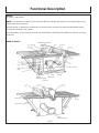
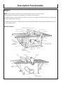
Functional Description
MODEL:
ET-3409-J TABLE SAW
NOTE: The information contained in this Instruction Manual is designed to assist you in the safe operation and
maintenance of the power tool.
NEVER operate, or attempt any maintenance on the tool unless you have first read and understood all safety
instructions contained in this manual.
Some illustrations in this Instruction Manual may show details or attachments that differ from those on your own
power tool.
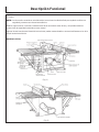
NAME OF PARTS:
(Fig. 1)
(Fig. 2)

Table Saw Operator's Manual 11
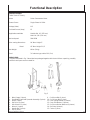
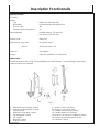
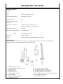
SPECIFICATIONS:
TABLE SAW ET-3409-J:
Motor Series Commutator Motor
Power Source Single-Phase AC 60Hz
Voltage (Volts) 115
Full-load Current (Amp) 15
Applicable saw blade Outside Dia. 10" (255 mm)
Hole Dia. 5/8" (15.9 mm)
No load speed 5000 RPM
Max. sawing dimensions: 90° Max. Height 3"
Bevel: 45° Max. Height 2-1/2"
Net Weight 64 lbs (29 kg)
Cord 3 Conductor type cable 6.6 ft (2 m)
UNPACKING:
The parts illustrated in Fig. 3 described are packaged together with the tool. When unpacking, carefully
confirm that all parts are accounted for.
Functional Description
1. Miter Gauge (1 piece)
2. Saw Blade Guard and Spreader Assembly (1 piece)
3. Elbow (1 piece)
4. Rip Fence (1 piece)
5. Hex. Wrench (1 piece)
6. Wrench (1 piece)
7. Handle Bar (1 piece)
8. Grip (1 piece)
9. 6 x 90 mm Bolt (1 piece)
10. 6 x 110 mm Bolt (1 piece)
11. 6 mm Spring Washer (2 pieces)
12. 6 mm Flat Washer (2 pieces)
13. 8 x 20 mm Bolt w/ Washers (4 pieces)
14. Set Plate (4 pieces)
15. Cusion (1 piece)
Fig. 3

12 Table Saw Operator's Manual
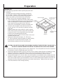
Preparation
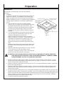
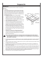
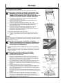
PREPARATION:
Make the following preparations before operating the power tool:
1. Installation:
The table saw must be properly secured to a sturdy work
bench, stand or cabinet. Casters (if provided) on the work
bench, stand or cabinet must be locked during operation. If
there is any tendency for the table saw to move during
operation, this must be corrected immediately. (Fig. 4)
a. Place the table saw in the desired location. Make certain
that is (or will be) adequate space on all sides of the table
saw for the workpiece. To allow maximum flexibility for
sheet material and long boards, 9 foot (2745 mm)
clearance is recommended on all sides of the table saw.
b. Secure the four set plates to the saw base at its four
corners with four 8 x 20 mm bolts (w/ washers) and four
8 mm nuts.
Square the table saw to the workbench, stand or cabinet.
Make certain that all controls are easily reached and there
is at least 6-11/16" (170 mm) behind the rear of the table
to allow for the saw blade guard assembly.
Temporarily mark the location of the four base corners and
set plate of the table saw.
c. Remove the table saw and locate a 11" (279 mm) or
12" (305 mm) square centered between the marks locating
the body shell. Cut out and remove the square. This
opening allows sawdust to fall out of the body shell.
(Fig. 4)
CAUTION: FAILURE TO PROVIDE THIS OPENING CAN RESULT IN INSUFFICIENT COOLING AIR TO
THE MOTOR CAUSING PREMATURE MOTOR FAILURE AND A POSSIBLE FIRE HAZARD.
d. Replace the table saw, aligning it with the marks made above. Trace hole positions on the four set plates on
the workbench, stand or cabinet with a pencil or the like.
e. Remove the table saw and drill a 5/16" (8 mm) hole in each location marked. Remove all sawdust or chips.
f. Replace the table saw in the marked location. Check to see that the table saw does not lock on the
workbench and all four set plates are in contact with the top of the workbench, stand or cabinet.
g. Using suitable length four 2" (50 mm) bolts, nuts and flat washer (not provided) secure the table saw to the
workbench, cabinet or stand. Place a spring washer and flat washer on the bolt, place the bolt through the
hole in the set plate and the top of the workbench stand, or cabinet. Add another flat washer and a nut. Do
not tighten the nut yet. Repeat this operation for the other three locations. Tighten all the nuts securely.
h. Check the sturdiness of the resulting assembly.

Table Saw Operator's Manual 13
Assembly
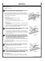
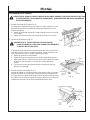
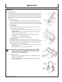
ASSEMBLY PROCEDURES:
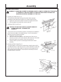
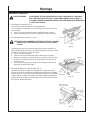
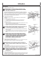
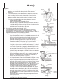
1. Assembly of Handle Bar (Fig. 5):
The handle bar allow faster turning of the wheel. When properly
assembled it will rotate freely but with only a small amount of play.
a. Tighten the screw of the handle bar until it hits against the wheel.
b. Securely tighten the handle bar nut with a wrench.
2. Installing of Rip Fence (Fig. 6):
CAUTION: THE RIP FENCE MUST BE ALIGNED PARALLEL
TO THE SAW BLADE TO MINIMIZE THE
KICKBACK.
The rip fence can be conveniently used to cut a workpiece into different
pieces of precise width or into parallel pieces. It can be mounted on
either the right or left side of the table.
a. Tighten the screw of the grip.
b. Catch the hook of the support in the bottom part of the rear rail.
c. Lower the rip fence in the arrow direction and fit the part of the width
body and support to the groove of the front and rear rail.
d. Confirm that the rip fence is moved right and left and it moves
smoothly.
3. Assembly of Miter Gauge (Fig. 7):
The miter gauge is convenient for cutting long or angular pieces which
are difficult to work on with the rip fence. It can be mounted on either the
right or left side of the table. Align the sheet bar of miter gage with the
miter gauge groove and slide it in the direction indicated by the arrow
through the front of the table.
(Fig. 5)
WARNING: TO AVOID AN ACCIDENT OR PERSONAL INJURY, ALWAYS CONFIRM THAT THE SWITCH
IS TURNED OFF AND THE POWER PLUG HAS BEEN DISCONNECTED FROM THE
RECEPTACLE BEFORE ASSEMBLY OF THIS TOOL.
(Fig. 6)
(Fig. 7)

14 Table Saw Operator's Manual
Assembly
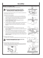
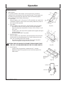
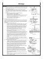
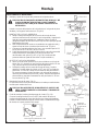
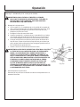
ASSEMBLY PROCEDURES (CONT.):
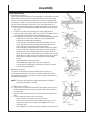
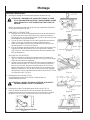
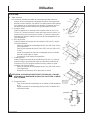
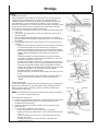
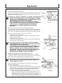
4. Mounting and adjusting Saw Blade Guard Assembly:
CAUTION: THE SAW BLADE GUARD AND SPREADER
ASSEMBLY MUST BE ALIGNED PROPERLY TO THE
SAW BLADE IN ORDER TO PREVENT KICKBACK.
Mount the saw blade guard assembly, which includes the spreader and
anti-kickback pawls. (Fig. 8-d)
MOUNTING THE SPREADER:
a. Loosen the saw blade tilt lock handle, move the saw blade tilting
mechanism to the left and set the saw blade to 0° by means of the
stopper. Tighten the saw blade tilt lock handle to lock it in position.
b. Turn the wheel fully clockwise and set the saw blade to the
maximum cutting height. (Fig. 8-a)
c. Put a 6 mm spring washer and a D13 flat washer on to the
6 x 90 mm and 6 x 110 mm bolts.
d. Tentatively fasten the spreader on the rear section of the body using
the cusion and two 6 mm bolts mentioned above. (Fig. 8-b and
Fig. 8-d) (The guard bracket must be attached to the spreader in
advance.)
ADJUSTING THE SPREADER:
a. Use a straight edge to align the spreader with the saw blade.
(Fig. 8-c) Tighten the two 6 x 16 mm bolts (Fig. 8-d) with a wrench to
lock the spreader.
b. Check clearance between saw blade tip and spreader. It should be
less than 1/2" (12.7 mm) at all positions. If not, loosen the two
6 x 16 mm bolts securing the spreader to the guard bracket with a
wrench and move the spreader up and down. After adjustment of the
spreader is complete, firmly retighten the two 6 x 16 mm bolts with a
wrench. (Fig. 8-d)
5. Mounting Table Insert (Fig. 9):
The table insert is mounted to the table with two 5 mm machine screws.
CAUTION: THE TABLE INSERT MUST BE IN PLACE AND
SECURELY FASTENED AT ALL TIMES.
6. Mounting Elbow (Chip Extraction Duct) (Fig. 10):
Connect a 2-9/16" (65 mm) hose to dust collector to the chip extraction
duct to suck cutting chips away. Mount the chip extraction duct on the
chip discharge outlet at the rear of the body.
(Fig. 8-a)
(Fig. 9)
(Fig. 8-b)
(Fig. 8-c)
(Fig. 8-d)
(Fig. 10)

Table Saw Operator's Manual 15
Assembly
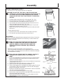
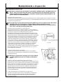
ASSEMBLY PROCEDURES (CONT.):
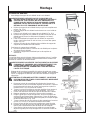
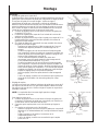
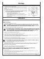
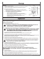
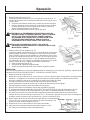
7. Assembly of the Table Saw Stand and The Table Saw:
WARNING: DO NOT USE THIS TABLE SAW STAND WITH ANY
OTHER TOOL. DO NOT STAND ON TABLE SAW STAND OR USE
AS LADDER OR SCAFFOLDING. MAXIMUM LOAD: 300 LBS
(136KG). DO NUT USE TABLE SAW STAND IF IT IS DAMAGED
OR BENT.
a. Unfold the table saw stand until it is fully opened. (Fig. 11-a)
b. Place the table saw stand upright on a solid flat level surface.
c. Place the table saw on the table saw stand. (Fig. 11-b)
d. Use the table saw stand and operate the table saw from the front
side (John Deere logo side) only. (Fig. 11-b)
e. Fasten the table saw to the table saw stand with 8 x 20 mm bolts
flanged nuts in all four corners. (Fig. 12)
f. Make sure the table saw is properly secured to the table saw stand
before use.
To close table saw stand:
a. Remove the four bolts, lift the table saw from table saw stand.
b. Pick the table saw stand up by the top rail and close it.
ADJUSTMENT:
This tool is accurately adjusted before shipping from the factory. Check the
following accuracies and readjust them if necessary in order to obtain the
best results in operation.
WARNING: TO AVOID AN ACCIDENT OR PERSONAL INJURY,
ALWAYS CONFIRM THAT THE SWITCH IS TURNED OFF
AND THE POWER PLUG HAS BEEN DISCONNECTED
FROM THE RECEPTACLE BEFORE ADJUSTMENT OF
THIS TOOL.
1. Adjustment of saw blade parallel to miter gauge groove:
This is the probably most difficult of the adjustments. Before shipment
from the factory, this adjustment was made but is should be rechecked
and readjusted if necessary.
CAUTION: THIS ADJUSTMENT MUST BE CORRECT. KICKBACK
COULD RESULT AND ACCURATE CUTS CANNOT BE
MADE.
a. Loosen the saw blade tilt lock handle by turning it counterclockwise.
Move the saw blade tilting mechanism to the left and set the saw
blade to 0° with the stopper.
b. Turn the wheel fully clockwise and set the saw blade to the maximum
cutting height. (See 13-a)
c. Select a tooth on the saw blade which is bent to the right.
d. Mark the tooth with a pencil or permanent marker.
e. Set the miter gauge to 90° and tighten the clamp handle (B) to lock it
in that position. Place the miter gauge in the left hand miter gauge
groove in the table top. (Fig. 13-b)
f. Rotate the saw blade to bring the marked tooth in the front and about
1/2" (12.7 mm) above the table top.
g. Place the bar of square flat against the miter gauge.
h. Move the bar of square toward the saw blade until it just touches the
top of the marked saw blade tooth.
i. Without disturbing the bar clamped to the miter gauge, move the
miter gauge to the center of the saw blade.
(Fig. 11-a)
(Fig. 13-b)
(Fig. 11-b)
(Fig. 12)
(Fig. 13-a)
BOLT

16 Table Saw Operator's Manual
Assembly
ADJUSTMENT (CONT.):
j. Slide the miter gauge rearward until the clamped bar is closest to the
tip of the marked saw blade tooth. (Fig. 13-c)
k. If the bar just touched the tooth when the gauge was in the front
position, it should just touch the tooth in the rear position. Likewise, if
there was some clearance between the bar and the tooth tip at the
front, the same clearance should be at the rear.
l. If the front and rear clearances are not identical;
- remove the miter gauge.
- loosen four 6 mm flat screws.
- move the body and adjust it so that a bar placed on the miter
gauge is as wide as the clearance between the front and rear
of the saw blade.
- tighten the four 6 mm flat screws.
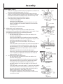
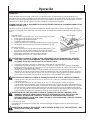
2. Adjusting 90° and 45° positive stops:
This tool is equipped with positive stops for rapid and accurate
positioning of the saw blade at 90° and left bevel 45° to the table. Check
and adjust the positive stops by the following procedures.
a. To adjust positive stop at 90°;
- turn the wheel fully clockwise and set the saw blade to the
maximum cutting height.
- loosen the saw blade tilt lock handle and move the saw blade
tilting mechanism to the left until it hits against the stopper. Then
tighten the saw blade tilt lock handle. (Fig. 14-a)
- use a square to check the saw blade is at a precise 90°.
(Fig. 14-b)
- if the saw blade is not at a precise 90°, loosen the saw blade tilt
lock handle by turning it counterclockwise. Loosen the 6 mm
machine screw (A) (Fig. 13-c) a few turns and move the saw
blade tilting mechanism until the blade is at 90° to the table.
(Fig. 14-b)
- tighten the saw blade tilt lock handle after adjustment.
- loosen the 5 mm machine screw and set the needle pointer to
0°. On completion of adjustment, recheck the 90° of the saw
blade and table. (Fig. 14-c)
b. To adjust positive stop at left bevel 45°;
- turn the wheel fully clockwise and set the saw blade to the
maximum cutting height.
- loosen the saw blade tilt lock handle and move the saw blade
tilting mechanism to the right until it hits against the stopper.
Then tighten the saw blade tilt lock handle. (Fig. 15-a)
- use a 45° gauge to check the saw blade is at a left bevel 45°.
(Fig. 15-b)
- if the saw blade is not at a left bevel 45°, loosen the saw blade tilt
lock handle. Loosen the 6 mm machine screw (A) (Fig. 13-c) a
few turns and move the saw blade tilting mechanism until the
blade is at left bevel 45° to the table. (Fig. 15-b)
- after adjustment, tighten the saw blade tilt lock handle.
- on completion of adjustment, recheck the left 45° bevel of the
saw blade and table.
(Fig. 13-c)
(Fig. 15-a)
(Fig. 14-a)
(Fig. 14-b)
(Fig. 14-c)

Table Saw Operator's Manual 17
Assembly
ADJUSTMENT (cont.):
3. Adjustment of rip fence.
Before shipment from the factory the saw blade is set parallel to the miter
gauge groove and the rip fence is adjusted parallel to the miter gauge
groove. Check and adjust the parallel of the rip fence by the following
procedures, in order, to have accurate work and prevent kickback when
ripping. Before adjustment of rip fence, check and adjust slider (it is
assembled under the width body) to engage with the groove on front rail.
a. Raise the grip to the upside and release the fixation of the rip fence.
(Fig. 16-a)
b. Position the rip fence at one edge of the miter gauge groove.
c. Lower the grip to the bottom and fix the rip fence. The edge of the rip
fence should line up parallel with the miter gauge groove.
d. If the edge of the rip fence is not parallel with the miter gauge groove;
- loosen the four 6 mm hex. head bolts securing the parallel
bracket to the width body and support.
- raise the grip to the upside and release the fixation of the rip
fence. Align the rip fence parallel to the miter gauge groove.
Lower the grip to the bottom and fix the rip fence.
- while holding the parallel bracket to prevent movement, tighten
the four 6 mm hex. head bolts previously loosened. (Fig. 16-b)
- raise the grip to the upside and release the fixation of the rip
fence. Move and return the parallel bracket adjacent to the miter
gauge groove. Lower the grip to the bottom and fix the rip fence.
Verify that the parallel bracket is parallel to the miter gauge
groove.
- repeat adjustment until it is parallel.
- after adjustment, tighten four 6 mm hex. head bolts.
- on completion of adjustment, recheck the rip fence is parallel
with the miter gauge groove.
4. Adjustment of pointer:
The pointer is equipped to indicate the distance the rip fence is
positioned away from the saw blade. The pointer should indicate the
accurate distance from the saw blade. Check and adjust the pointer by
the following procedures.
NOTE: The pointer will need to be readjusted whenever a different
thickness saw blade is installed.
To adjust pointer 0 setting.
a. Raise the grip to the upside and release the fixation of the rip fence.
And move the rip fence to bring it into tight contact with the side of
the saw blade.
b. Make sure that the pointer points to 0 on the scale provided on the
table.
c. If the pointer does not point to 0 on the scale;
- lower the grip to the bottom and fix the rip fence.
- loosen the 5 mm machine screw holding the pointer. (Fig. 17)
- adjust the pointer to the 0 position and retighten the 5 mm
machine screw.
- after adjustment, recheck to see that the pointer now points to 0.
(Fig. 16-a)
(Fig. 16-b)
(Fig. 17)
(Fig. 15-b)

18 Table Saw Operator's Manual
Operation
APPLICATIONS:
Wood (hard or soft woods)
PRE-OPERATION:
1. Make sure the switch is turned OFF.
WARNING: IF THE POWER CORD IS CONNECTED TO THE POWER SOURCE WITH THE
SWITCH TURNED ON THE POWER TOOL WILL START SUDDENLY AND CAN
CAUSE A SERIOUS ACCIDENT.
2. Make sure the power source is appropriate for the tool.
WARNING: NEVER CONNECT THE POWER TOOL UNLESS THE AVAILABLE AC POWER
SOURCE IS OF THE SAME VOLTAGE IS THAT SPECIFIED ON THE NAMEPLATE OF
THE TOOL. NEVER CONNECT THIS POWER TOOL TO A DC POWER SOURCE.
3. Check the saw blade for visible defects.
Confirm that the saw blade is free of cracks or other visible damage.
4. Confirm that the saw blade is attached securely to the power tool.
Using the supplied wrench, tighten the set nut on the saw blade spindle to secure the saw blade. For details,
see Fig. 33 in the section on "SAW BLADE MOUNTING AND DISMOUNTING."
5. Check the safety cover for proper operation.
Saw blade guard is designed to protect the operator from coming into contact with the saw blade during
operation of the tool. Always check that the safety blade guard moves smoothly.
WARNING: NEVER OPERATE THE POWER TOOL IS THE SAW BLADE GUARD DOES NOT
FUNCTION SMOOTHLY.
6. Check the Power Receptacle.
To prevent overheating, accidental stopping or intermittent operation, confirm that the power cord plug fits
properly in the electrical receptacle and does not fall out after it is inserted. Repair and replace the receptacle if
it is faulty.
7. Confirm the tool's power cord is not damaged.
Repair or replace the power cord if an inspection indicates that it is damaged.
AFTER CONNECTING THE POWER PLUG TO AN APPROPRIATE AC POWER SOURCE, CHECK THE
OPERATION OF THE TOOL AS FOLLOWS:
8. Trial Run.
After confirming that no one is standing behind the power tool, start and confirm that no operating abnormalities
exist before attempting a cutting operation.
9. Inspect the rotating stability of the saw blade.
For precise cutting, rotate the saw blade and check for deflection to confirm that the blade is not noticeably
unstable; otherwise, vibrations might occur and cause an accident.
Assembly
ADJUSTMENT (cont.):
5. Adjustment of miter gauge:
The miter gauge should be square to the saw blade. Check and adjust
the milter gauge the following procedures.
To adjust pointer 0 setting.
a. Loosen the clamp handle (B) and place a square against both the
saw blade and miter gauge. The pointer should indicate 90° on the
protractor scale on the miter gauge.
b. If the pointer does not point to 0 on the miter gauge;
- tighten clamp handle (B).
- loosen the 5 mm machine screw on the sheet bar.
- adjust the pointer to the 90° position and tighten the 5 mm
machine screw on the sheet bar. (Fig. 18)
- after adjustment, recheck to see that the pointer now points to 0.
(Fig. 18)

Table Saw Operator's Manual 19
Operation
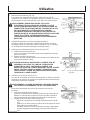
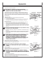
PRACTICAL OPERATIONS:
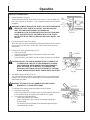
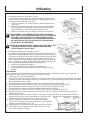
1. Switch Operations (Fig. 19):
To turn the table saw ON, lift the lever of the switch. To turn the table saw
OFF, push the lever of the switch. Try this operation without the saw being
plugged in.
WARNING: ALWAYS REMOVE THE SAFETY KEY FROM THE SWITCH
WHEN THE TABLE SAW IS NOT IN USE. THIS WILL ENSURE
THAT THE TABLE SAW CANNOT BE TURNED ON
ACCIDENTALLY OR BY SOMEONE (ESPECIALLY A CHILD) WHO
IS NOT QUALIFIED TO USE THE TABLE SAW. IF THE SAFETY
KEY IS LEFT IN THE SWITCH, SERIOUS PERSONAL INJURY CAN
RESULT.
2. Overload Protective Device for Motor:
When the motor becomes overload, the overload protective device cuts off
the current to stop the motor. In this case, after a few minutes, push the
reset button.
3. Raising and Lowering Saw Blade (Fig. 20):
a. Raising saw blade.
Grasp the wheel and rotate it clockwise to raise the saw blade.
b. Lowering saw blade.
Grasp the wheel and rotate it counterclockwise to lower the saw blade.
CAUTION: ADJUST THE SAW BLADE HEIGHT SO IT IS ABOUT 1/8"
(3.2 MM) ABOVE THE TOP OF THE WORKPIECE. RAISING
THE SAW BLADE MUCH HIGHER THAN THE WORKPIECE
DOES NOT MAKE IT CUT BETTER. IT IS UNSAFE AND
PROVIDES LESS TABLE SURFACE IN FRONT OF THE SAW
BLADE. NEVER OPERATE WHILE SAW BLADE IS ROTATING.
4. Saw Blade Tilting Operation (Fig. 21):
The saw blade tilt lock handle is spring loaded and can be repositioned by
pulling out on the handle and repositioning it on the serrated stud located
underneath the handle.
WARNING: THE SAW TILT LOCK HANDLE MUST BE LOCKED
DURING ALL CUTTING OPERATIONS.
To methods are available tilting saw blade and are as follows.
a. Rapid saw blade tilting.
Loosen saw blade tilt lock handle, move the wheel until the saw blade
is at the desired angle and tighten saw blade tilt lock handle.
b. Fine adjustment saw blade tilting;
- loosen saw blade tilt lock handle.
- push in wheel until teeth on hub of hand wheel engage with
segment gear.
- turn wheel to tilt the saw blade to the desired angle and tighten
saw blade tilt lock handle.
(Fig. 19)
(Fig. 20)
(Fig. 21)

20 Table Saw Operator's Manual
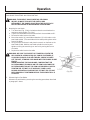
PRACTICAL OPERATIONS (cont.):
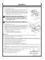
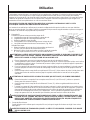
5. Rip Fence Operation (Fig. 22):
The rip fence can be used on either side of the saw blade. The pointer on
rip fence indicates the distance between the saw blade and rip fence.
a. Raise the grip to the upside and release the fixation of the rip fence.
b. Move the rip fence right and left while pressing the width body against
the table surface and set the desired distance form the saw blade.
c. Lower the grip to the bottom and fix the rip fence.
WARNING: THE GRIP MUST BE LOCKED DURING ALL CUTTING
OPERATIONS. CONFIRM THE RIP FENCE HAS BEEN
PROPERLY LOCKED BEFORE OPERATION. TO PREVENT
PERSONAL INJURY, NEVER OPERATE THE POWER TOOL IF
THE RIP FENCE IS LOOSE.
CAUTION: MAKE SURE THAT THE RIP FENCE IS ALWAYS IN
PARALLEL WITH THE MITER GAUGE GROOVE ON THE TABLE.
6. Miter Gauge Operation (Fig. 23):
The miter gauge can be used on either side of the miter gauge grooves on
the table. However, for bevel cutting (the saw blade is tilted), use the miter
gauge in the right side miter gauge groove to prevent hands or miter
gauge form interfering with the saw blade guard. Miter gauge is accurately
adjustable at 90° and 45° right and left in relation to the saw blade.
Intentional miter cut angle can be obtained easily.
a. Loosen clamp handle (B).
b. Turning the miter gauge to the desired angle.
c. Tighten clamp handle (B) to lock the miter gauge.
Operation
(Fig. 23)
(Fig. 24)
OPERATION:
For your own safety carefully read and observe the following warnings and precautions in addition to the
IMPORTANT INFORMATION, SAFETY AND WARNINGS.
1. The saw blade is firmly locked.
2. Never perform any operation "free hand" without using the miter gauge, rip fence and / or other auxiliary devices.
To do so could cause accidents from kickback should the saw blade become locked in the workpiece material.
3. When miter gauge is used, remove rip fence from table.
4. When the miter gauge is used, securely tighten clamp handle (B).
5. When rip fence is used, remove miter gauge from table.
6. When the rip fence is used, securely lock the grip.
7. If blade stalls or stops, TURN SWITCH OFF before releasing blade.
8. Never attempt to remove small cut-off pieces with your fingers. Remove them by pushing them clear with a long
stick.
9. Never attempt to remove small cut-off pieces trapped inside the saw blade guard while the saw is running. Turn
the switch "OFF", allow the saw blade to come to a complete stop, raise the saw blade guard and remove the
cut-offs.
10. Adjust the saw blade height so it is about 1/8" (3.2 mm) above the top of
the workpiece. More exposure would be hazardous. (Fig. 24)
11. Never touch any cut-offs while saw blade is running.
12. Feed material slowly in order to make fine cut,
keep accuracy and avoid overloading.
(Fig. 22)
La page est en cours de chargement...
La page est en cours de chargement...
La page est en cours de chargement...
La page est en cours de chargement...
La page est en cours de chargement...
La page est en cours de chargement...
La page est en cours de chargement...
La page est en cours de chargement...
La page est en cours de chargement...
La page est en cours de chargement...
La page est en cours de chargement...
La page est en cours de chargement...
La page est en cours de chargement...
La page est en cours de chargement...
La page est en cours de chargement...
La page est en cours de chargement...
La page est en cours de chargement...
La page est en cours de chargement...
La page est en cours de chargement...
La page est en cours de chargement...
La page est en cours de chargement...
La page est en cours de chargement...
La page est en cours de chargement...
La page est en cours de chargement...
La page est en cours de chargement...
La page est en cours de chargement...
La page est en cours de chargement...
La page est en cours de chargement...
La page est en cours de chargement...
La page est en cours de chargement...
La page est en cours de chargement...
La page est en cours de chargement...
La page est en cours de chargement...
La page est en cours de chargement...
La page est en cours de chargement...
La page est en cours de chargement...
La page est en cours de chargement...
La page est en cours de chargement...
La page est en cours de chargement...
La page est en cours de chargement...
La page est en cours de chargement...
La page est en cours de chargement...
La page est en cours de chargement...
La page est en cours de chargement...
La page est en cours de chargement...
La page est en cours de chargement...
La page est en cours de chargement...
La page est en cours de chargement...
La page est en cours de chargement...
La page est en cours de chargement...
La page est en cours de chargement...
La page est en cours de chargement...
La page est en cours de chargement...
La page est en cours de chargement...
La page est en cours de chargement...
La page est en cours de chargement...
La page est en cours de chargement...
La page est en cours de chargement...
La page est en cours de chargement...
La page est en cours de chargement...
-
 1
1
-
 2
2
-
 3
3
-
 4
4
-
 5
5
-
 6
6
-
 7
7
-
 8
8
-
 9
9
-
 10
10
-
 11
11
-
 12
12
-
 13
13
-
 14
14
-
 15
15
-
 16
16
-
 17
17
-
 18
18
-
 19
19
-
 20
20
-
 21
21
-
 22
22
-
 23
23
-
 24
24
-
 25
25
-
 26
26
-
 27
27
-
 28
28
-
 29
29
-
 30
30
-
 31
31
-
 32
32
-
 33
33
-
 34
34
-
 35
35
-
 36
36
-
 37
37
-
 38
38
-
 39
39
-
 40
40
-
 41
41
-
 42
42
-
 43
43
-
 44
44
-
 45
45
-
 46
46
-
 47
47
-
 48
48
-
 49
49
-
 50
50
-
 51
51
-
 52
52
-
 53
53
-
 54
54
-
 55
55
-
 56
56
-
 57
57
-
 58
58
-
 59
59
-
 60
60
-
 61
61
-
 62
62
-
 63
63
-
 64
64
-
 65
65
-
 66
66
-
 67
67
-
 68
68
-
 69
69
-
 70
70
-
 71
71
-
 72
72
-
 73
73
-
 74
74
-
 75
75
-
 76
76
-
 77
77
-
 78
78
-
 79
79
-
 80
80


John Deere Saw ET-3409-J Manuel utilisateur
- Catégorie
- Outils électroportatifs
- Taper
- Manuel utilisateur
- Ce manuel convient également à
dans d''autres langues
Documents connexes

Autres documents
-
Hitachi C 10RA2 Manuel utilisateur
-
-
Bosch 4000 Le manuel du propriétaire
-
Skil 3305-01 Manuel utilisateur
-
Bosch 4100DG Le manuel du propriétaire
-
Bosch Power Tools 4000 Manuel utilisateur
-
DeWalt DW744S TYPE 2 Le manuel du propriétaire
-
-
SKILSAW SPT99-12 Manuel utilisateur
-
DeWalt DW745 TYPE 3 Le manuel du propriétaire