
Revised - 07/19/2017
Toll Free: 1-800-465-0234
Fax: 905-607-0234
Email: [email protected]
www.omcan.com
3182799
Gas Griddles
Models CE-CN-G15M, G24M, G36M, G48M, G15TPF,
G24TPF, G36TPF, G48TPF
Items 43737, 43730, 43731, 43732, 43016, 43017, 43018, 43019
Instruction Manual

2
Page
--------------------------------------------------------------------------- 3 - 4
--------------------------------------------------------------------------- 4 - 6
-------------------------------------------------------------------------- 6
-------------------------------------------------------------------------------------- 7 - 12
------------------------------------------------------------------------------------- 12 - 13
--------------------------------------------------------------------------------------- 14
----------------------------------------------------------------------------- 14 - 15
----------------------------------------------------------------------- 15 - 26
---------------------------------------------------------------------------- 27 - 31
------------------------------------------------------------------------------------------- 32 - 34
---------------------------------------------------------------------------- 35
Table of Contents
Section
General Information
Safety and Warranty
Technical Specications
Installation
Operation
Maintenance
Troubleshooting
Instructions Français
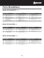
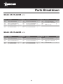
Parts Breakdown
Notes
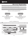
Warranty Registration
Model CE-CN-G15TPF / Model CE-CN-G24TPF / Model CE-CN-G36TPF
Model CE-CN-G48TPF / Model CE-CN-G15M / Model CE-CN-G24M
Model CE-CN-G36M / Model CE-CN-G48M

3
General Information
Omcan Manufacturing and Distributing Company Inc., Food Machinery of America, Inc. dba Omcan
and Omcan Inc. are not responsible for any harm or injury caused due to any person’s improper or
negligent use of this equipment. The product shall only be operated by someone over the age of 18, of
sound mind, and not under the inuence of any drugs or alcohol, who has been trained in the correct
operation of this machine, and is wearing authorized, proper safety clothing. Any modication to the
machine voids any warranty, and may cause harm to individuals using the machine or in the vicinity of
the machine while in operation.
CHECK PACKAGE UPON ARRIVAL
Upon receipt of an Omcan shipment please inspect for external damage. If no damage is evident on the
external packaging, open carton to ensure all ordered items are within the box, and there is no concealed
damage to the machine. If the package has suffered rough handling, bumps or damage (visible or concealed),
please note it on the bill of lading before accepting the delivery and contact Omcan within 24 hours, so we may
initiate a claim with the carrier. A detailed report on the extent of the damage caused to the machine must be
lled out within three days, from the delivery date shown in the shipping documents. Omcan has no recourse
for damaged products that were shipped collect or third party.
Before operating any equipment, always read and familiarize yourself with all operation and safety
instructions.
Omcan would like to thank you for purchasing this machine. It’s of the utmost importance to save
these instructions for future reference. Also save the original box and packaging for shipping the
equipment if servicing or returning of the machine is required.
---------------------------------------------------------------------------------------------------------------------------------------------------
Omcan Fabrication et distribution Companie Limité et Food Machinery d’Amerique, dba Omcan et
Omcan Inc. ne sont pas responsables de tout dommage ou blessure causé du fait que toute personne
ait utilisé cet équipement de façon irrégulière. Le produit ne doit être exploité que par quelqu’un de
plus de 18 ans, saine d’esprit, et pas sous l’inuence d’une drogue ou d’acohol, qui a été formé pour
utiliser cette machine correctement, et est vêtu de vêtements de sécurité approprié. Toute modication
de la machine annule toute garantie, et peut causer un préjudice à des personnes utilisant la machine
ou des personnes à proximité de la machine pendant son fonctionnement.
VÉRIFIEZ LE COLIS DÈS RÉCEPTION
Dès réception d’une expédition d’Omcan veuillez inspecter pour dommages externes. Si aucun dommage
n’est visible sur l’emballage externe, ouvrez le carton an de s’assurer que tous les éléments commandés
sont dans la boîte, et il n’y a aucun dommage dissimulé à la machine. Si le colis n’a subi aucune mauvaises
manipulations, de bosses ou de dommages (visible ou cachée), notez-le sur le bond de livraison avant
d’accepter la livraison et contactez Omcan dans les 24 heures qui suivent, pour que nous puissions engager
une réclamation auprès du transporteur. Un rapport détaillé sur l’étendue des dommages causés à la machine
doit être rempli dans un délai de trois jours, à compter de la date de livraison indiquée dans les documents
d’expédition. Omcan n’a aucun droit de recours pour les produits endommagés qui ont été expédiées ou cueilli
par un tiers transporteur.

4
General Information
Avant d’utiliser n’importe quel équipement, toujours lire et vous familiariser avec toutes les opérations
et les consignes de sécurité.
Omcan voudrais vous remercier d’avoir choisi cette machine. Il est primordial de conserver ces
instructions pour une référence ultérieure. Également conservez la boîte originale et l’emballage pour
l’expédition de l’équipement si l’entretien ou le retour de la machine est nécessaire.
---------------------------------------------------------------------------------------------------------------------------------------------------
Omcan Empresa De Fabricacion Y Distribucion Inc. Y Maquinaria De Alimentos De America, Inc. dba
Omcan y Omcan Inc. no son responsables de ningun daño o perjuicío causado por cualquier persona
inadecuada o el uso descuidado de este equipo. El producto solo podra ser operado por una persona
mayor de 18 años, en su sano juicio y no bajo alguna inuencia de droga o alcohol, y que este ha sido
entrenado en el correcto funcionamiento de esta máquina, y ésta usando ropa apropiada y autorizada.
Cualquier modicación a la máquina anúla la garantía y puede causar daños a las personas usando la
máquina mientras esta en el funcionamiento.
REVISE EL PAQUETE A SU LLEGADA
Tras la recepcion de un envio Omcan favor inspeccionar daños externos. Si no hay daños evidentes en el
empaque exterior, Habra el carton para asegurararse que todos los articulos solicitados ésten dentro de la
caja y no encuentre daños ocultos en la máquina. Si el paquete ha sufrido un manejo de poco cuidado, golpes
o daños (visible o oculto) por favor anote en la factura antes de aceptar la entrega y contacte Omcan dentro
de las 24 horas, de modo que podamos iniciar una reclamación con la compañia. Un informe detallado sobre
los daños causados a la máquina debe ser llenado en el plazo de tres días, desde la fecha de entrega que se
muestra en los documentos de envío. Omcan no tiene ningun recurso por productos dañados que se enviaron
a recoger por terceros.
Antes de utilizar cualquier equipo, siempre lea y familiarizarse con todas las instrucciones de
funcionamiento y seguridad.
Omcan le gustaría darle las gracias por la compra de esta máquina. Es de la mayor importancia para
salvar estas instrucciones para futuras consultas. Además, guarda la caja original y el embalaje para el
envío del equipo si servicio técnico o devolución de la máquina que se requiere.
Safety and Warranty
GAS PRESSURE
The appliance and its individual shutoff valve (to be supplied by user) must be disconnected from the gas
supply piping system during any pressure testing of that system at test pressures in excess of ½ psi (3.45
kPa). The appliance must be isolated from the gas supply piping system by closing its individual manual shut-
off valve during any pressure testing of the gas supply piping system at test pressures equal to or less than ½
psi (3.45 kPa).

5
Safety and Warranty
• For your safety, do not store or use gasoline or other ammable vapors or liquids in the vicinity of this or
any other appliances. Keep the area free and clear of combustible. ( See ANSI Z83. 14B, 1991).
• Improper installation, adjustment, alteration, service or maintenance can cause property damage, injury,
or death. Read the installation operating and maintenance instructions thoroughly before installing, or
servicing this equipment.
• Instructions must be posted in a prominent location. All safety precautions must be taken in the event the
user smells gas. Safety information can be obtained from your local gas supplier.
• These models are designed, built, and sold for commercial use only. If these models are positioned so
the general public can use the equipment, make sure that cautions, warnings, and operating instructions
are clearly posted near each unit so that anyone using the equipment will use it correctly and not injure
themselves or harm the equipment.
• A factory authorized agent should handle all maintenance and repair. Before doing any maintenance or
repair, contact your authorized service representative.
• This product is intended for commercial use only. Not for household use.
• Installation must comply with all local codes.
DANGER: This warns of imminent hazard, which could result in serious injury or death.
WARNING: This refers to a potential hazard or unsafe practice, which could result in serious injury or
death.
CAUTION: This refers to a potential hazard or unsafe practice, which could result in minor or moderate
injury or product or property damage.
NOTICE: This refers to information that needs special attention or must be fully understood even
though not dangerous.
NOTICE: Local codes regarding installation vary greatly from one area to another. The National Fire
Protection Association, Inc., states in its NFPA96 latest edition that local codes are “Authority Having
Jurisdiction” when it comes to requirement for the installation of equipment. Therefore, the installation
should comply with all local codes.
1 YEAR PARTS AND LABOUR WARRANTY
Within the warranty period, contact Omcan Inc. at 1-800-465-0234 to schedule an Omcan authorized
service technician to repair the equipment locally.
Unauthorized maintenance will void the warranty. Warranty covers electrical and part failures, not
improper use.
Please see www.omcan.com/warranty.html for complete info.
WARNING:
The packaging components are classied as normal solid urban waste and can therefore be disposed of

6
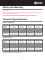
Technical Specications
GRIDDLE (THERMOSTAT)
Model CE-CN-G15TPF CE-CN-G24TPF CE-CN-G36TPF CE-CN-G48TPF
Cooking
Dimensions
15” x 20”
377 x 510mm
24” x 20”
606 x 510mm
36” x 20”
911 x 510mm
48” x 20”
1216 x 510mm
# of Burners 1 2 3 4
BTU per Burner 30,000
BTU per Hour 30,000 60,000 90,000 120,000
Pressure in W.C 6/10
Dimensions
15” x 32.7” x 16.7”
381 x 830 x 425mm
24” x 32.7” x 16.7”
610 x 830 x 425mm
36” x 32.7” x 16.7”
915 x 830 x 425mm
48” x 32.7” x 16.7”
1220 x 830 x 425mm
Item Number 43016 43017 43018 43019
GRIDDLE (MANUAL)
Model CE-CN-G15M CE-CN-G24M CE-CN-G36M CE-CN-G48M
Cooking
Dimensions
15” x 20”
377 x 510mm
24” x 20”
606 x 510mm
36” x 20”
911 x 510mm
48” x 20”
1216 x 510mm
# of Burners 1 2 3 4
BTU per Burner 30,000
BTU per Hour 30,000 60,000 90,000 120,000
Pressure in W.C 6/10
Dimensions
15” x 32.7” x 16.7”
381 x 830 x 425mm
24” x 32.7” x 16.7”
610 x 830 x 425mm
36” x 32.7” x 16.7”
915 x 830 x 425mm
48” x 32.7” x 16.7”
1220 x 830 x 425mm
Item Number 43737 43730 43731 43732
Note: Depth Direction includes the regulator Size
Safety and Warranty
without difculty.
In any case, for suitable recycling, we suggest disposing of the products separately (differentiated
waste) according to the current norms.
DO NOT DISCARD ANY PACKAGING MATERIALS IN THE ENVIRONMENT!

7
Installation
Ensure gas supply and gas type, are as shown on unit nameplate.
Unit installation must conform with the National Fuel Gas Code, ANSI Z223.1/NFPA 54, the National
Gas Installation Code, CSA-B149.1, or the Propane Installation Code, CSA-B149.2 as applicable and in
accordance with local codes.
Screw legs into the permanently fastened nuts on the four corners of the unit and tighten by hand. Level
the unit by turning the adjustment screw at the bottom of each leg. Do not slide unit with legs mounted, lift if
necessary to move unit.
Pipe threading compound must be resistant to the action of liqueed petroleum gases.
Caution: DO NOT use an open ame to check for leaks. Check all gas piping for leaks with a soap and
water solution before operating unit.
THESE UNITS ARE SUITABLE FOR INSTALLATION ON NON-COMBUSTIBLE
SURFACES ONLY
Combustible clearances:
• 6” sides (152 mm).
• 6” rear (152 mm).
• 4” oor (102 mm).
Noncombustible clearances:
• 0” sides (0 mm).
• 0” rear (0 mm).
• 4” oor (102 mm).
Do not obstruct the ow of combustion and ventilation air, under the unit by the legs or behind the unit by
the ue. Adequate clearance for air openings into the combustion chamber is required. Do not place objects
between the bottom of the unit and the counter top. There must be adequate clearance for removal of the front
panel. All major parts except the burners are removable thru the front if the gas line is disconnected.
CONVERSION
These instructions are for the conversion from Natural Gas to Propane (L.P.) on all models. The conversion
should be done before connecting the unit to the gas supply. Units are shipped from the factory equipped for
use on natural gas.

8
Installation
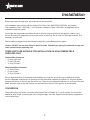
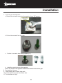
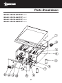
1. Shut-off the main isolation gas valve and follow the lock-out/tag-out procedure.
2. Pull-out and remove all the Dials.
Remove the Tray for ease of access.
3. Remove the screws of the control panel.
Tray
Knob

9
Installation
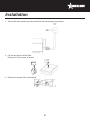
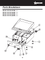
4. Remove the Back-Panel and Nut for U Burners.
5. Remove the U Burners.
Back-Panel
Nut
U Burner

10
Installation
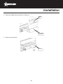
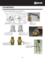
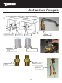
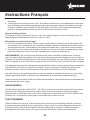
6. Remove the Orice and Replace it. Use a 1/2” spanner.
See the list of Orice numbers for the appropriate gas type.
Main Burner Valve
Pilot Valve
Orifice
Orifice
Use for Propane
(L.P.)
Use for Natural Gas
Pilot Orifice
Use for Natural Gas
Use for Propane
(L.P.)

11
Installation
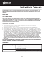
7. Converting the Gas Regulator.
a. Remove the converter cover from the regulator. Use a 7/8” spanner.
b. Pull-out the converter from the cover.
c. Position of converter when using Propane (L.P.)
d. Install the converter cover to the regulator.
Note: The arrow in the regulator indicates the ow direction of the gas.
8. Re-install the U burners.
9. Check leakage and re-install other parts.
10. Ignite the pilot burner and check ame state.
11. Turn the knobs to “High”.

12
Operation
Installation
LIGHTING INSTRUCTIONS
FOR THERMOSTAT MODELS
Lighting the Main Burners
These Griddles are tted with individual standing pilots for each burner. Flame Failure Protection is
incorporated for each burner by way of a thermo-electric system which will shut off the gas supply to that
burner in the event that the burner goes out, so that un-burnt gas is not expelled.
• Select the burner required, depress and turn the corresponding gas control knob anti-clockwise to the
‘PILOT’ position.
• With the gas control knob depressed, manually light the pilot burner.
• Release the gas control knob after approximately 10-20 seconds after lighting the pilot burner.
• The pilot burner should stay alight - if not, repeat the above steps.
• Rotate the gas control knob anti-clockwise to the desired temperature mark.
• The main burner will be now ignited automatically.
Turning ‘OFF’ the Main Burners / Pilots
• To turn ‘OFF’ the main burner, but keep the pilot burner lit, rotate the gas control knob to the ‘PILOT’
position. The main burner will extinguish and the pilot will remain lit.
• To turn ‘OFF’ the ‘PILOT’, depress and turn the gas control knob clockwise back to the ‘OFF’ position. The
‘PILOT’ burner will extinguish.
Note: Please wait at least 15 seconds to restart the main burners to maintain the best function of the
thermostat valve after turning off the main burners.
FOR MANUAL MODELS
The pilot light on the appliance has been set at the factory. A screwdriver maybe required for the rst lighting to
adjust the ame for your elevation.
1. Turn off the manual valve and wait 5 minutes to clear the gas.
2. Turn all knobs to the “OFF” position.
3. Hold an ignition source (match) at the pilot. When the ame is established, remove the ignition source.
4. Turn the burner knobs to “ON”. If the burner does not ignite, promptly open the pilot valve more. If the pilot
• If the U burner does not ignite, open the pilot valve more.
• If the pilot ame appears larger than necessary, turn it down and reset burner ignition.
• The pilot ame should be as small as possible but large enough to guarantee reliable ignition of the burners
when the knobs are turned to “I”
Note: Please check leakage before re-installing the control-panel.

13
Operation
ame appears larger than necessary, turn it down and reset burner ignition. The pilot ame should be as
small as possible but large enough to guarantee reliable ignition of the burners when the knobs are turned
to “ON”.
Lighting main burner
To light burner, turn knob to “ON.” Then back off to the desired ame level. The range of adjustment is virtually
innite between “ON” and “OFF”.
Main burner air supply
1. For efcient burner operation, a proper balance of gas volume and primary air supply must be maintained
which will result in complete combustion. Insufcient air supply results in a yellow streaming ame. Primary
air supply is controlled by an air shutter on the front of the burner.
2. Loosen the screws on the front of the burner and adjust the air shutter to just eliminate the yellow tips of
the burner ame. Lock the air shutter in place by tightening the screws.
CAUTION: All burners are lit from constantly burning pilots. Turning the valve to the desired ame height is
all that is required to put the unit in service. Do not permit fans to blow directly at the unit. Wherever possible,
avoid open windows next to the unit’s sides or back. Avoid wall-type fans, which create air crosscurrents within
a room.
It is also necessary that sufcient air should be allowed to enter the room to compensate for the amount of
air removed by any ventilating system. Otherwise, a subnormal atmospheric pressure will occur, affecting
operation and causing undesirable working conditions.
A properly designed and installed hood will act as the heart of the ventilating system for the room or area in
which the unit is installed, and will leave the unit independent of changing draft conditions.
All valves must be checked and lubricated periodically. This must be done by an authorized service
representative in your area.
SEASON GRIDDLE
Heat to low temperature (300 - 350°F/150-180°C) and pour on a small amount of cooking oil, about one ounce
(30cc) per square foot of surface. Spread the oil over the entire griddle surface with a cloth to create a thin lm.
Wipe off any excess oil with a cloth. Repeat this procedure 2 to 3 times until the griddle has a slick, mirror-like
surface.
OPERATION
Turn the burners on about 15-20 minutes before cooking for preheating. Set the knobs to the desired ame
height or temperature. Each valve will control the gas ow to the burner to bring that area of the unit up to the
set temperature. If different temperature settings are to be used, adjoining areas should be set at progressively
higher temperatures using the lowest temperatures on the outside burners. A uniform and systematic approach
to the loading of the unit will produce the most consistent product results.

14
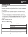
Troubleshooting
Troubles Possible Causes
Pilot burner cannot be lit. The pilot valve is obstructed.
Pilot gas turned off pilot valve.
The pilot valve is bad.
Fat appears to smoke excessively. Griddle plate is too hot.
Moisture in the food may be turning into steam.
Food sticks to griddle. Griddle plate is too hot.
Griddle surface needs cleaning and/or seasoning.
Surface under food may not have been covered with enough cooking
oil.
Food burned around edges or
contains dark specks.
Griddle plate is too hot.
Griddle surface needs cleaning and/or seasoning.
Surface under food may not have been covered with enough cooking
oil.
Maintenance
INITIAL CLEANING
Prior to operating your new griddle, thoroughly wash the griddle surface and the exterior with a mild detergent
or soap solution. Do not use abrasive cleaners since this might damage the cabinet nish. If the stainless steel
surfaces become discolored, scrub by rubbing only in the direction of the nished grain.
DAILY CLEANING
1. Always turn unit off and allow it to cool completely before cleaning. Clean thoroughly before rst use.
2. After each use, clean the griddle with wire brush or exible spatula.
3. Once a day, thoroughly clean splash back, sides and front. Remove the grease drawer, empty it and wash
it out.
4. Once a week, clean the griddle surface thoroughly. If necessary, use a griddle stone, wire brush or steel
wool on the surface. Rub with the grain of the metal while the griddle is still warm. A detergent may be
used on the plate surface to help clean it; but, care must be taken to be sure the detergent is thoroughly
removed. After removal of the detergent, the surface of the plate should then be covered with a thin lm of
oil to prevent rusting. Clean stainless surfaces with a damp cloth and polish with a soft dry cloth. To remove
discoloration, use a nonabrasive cleaner. After each “weekly” cleaning, the griddle must be seasoned
again. If the griddle usage is very high, the “weekly” cleaning procedures may be done more often than
once a week.
NOTE: Parts protected by the manufacturer or his agent are not to be adjusted by the installer, unless
the installer is an authorized service agent.

15
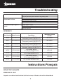
Troubleshooting
Instructions Français
Food is under cooked inside. Griddle plate is too hot
Food may not have been cooked for long enough time.
Food tastes greasy or has
objectionable off-avor.
Griddle plate is too hot.
Food itself may have off avor.
Food may have been stored improperly before cooking.
Too much fat used.
Noticeable build-up of gum on
griddle.
Griddle plate is too hot.
Griddle surface needs cleaning and/or seasoning.
Too much fat used.
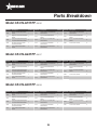
REFERENCE
Item Number Model Number Description
Manufacturer Model
Number
43016 CE-CN-G15TPF
Gas Griddle 1 Burner 15” / 381mm with
Thermostat Controls 30,000 BTU ETL
UR-G15TPF
43017 CE-CN-G24TPF
Gas Griddle 2 Burners 24” / 610mm with
Thermostat Controls 60,000 BTU ETL
UR-G24TPF
43018 CE-CN-G36TPF
Gas Griddle 3 Burners 36” / 914mm with
Thermostat Controls 90,000 BTU ETL
UR-G36TPF
43019 CE-CN-G48TPF
Gas Griddle 4 Burners 48” / 1219mm with
Thermostat Controls 120,000 BTU ETL
UR-G48TPF
43737 CE-CN-G15M
Gas Griddle 1 Burner
15” / 381mm 30,000 BTU ETL
UR-G15M
43730 CE-CN-G24M
Gas Griddle 2 Burners
24” / 610mm 60,000 BTU ETL
UR-G24M
43731 CE-CN-G36M
Gas Griddle 3 Burners
36” / 914mm 90,000 BTU ETL
UR-G36M
43732 CE-CN-G48M
Gas Griddle 4 Burners
48” / 1219mm 120,000 BTU ETL
UR-G48M
SÉCURITÉ ET GARANTIE
PRESSION DE GAZ
L’appareil et son robinet d’arrêt individuel (doit être fournie par l’utilisateur) doivent être débranchés du

16
Instructions Français
système de tuyauterie d’alimentation en gaz pendant les essais de pression de ce système à des pressions
d’essai supérieures à ½ psi (3,45 kPa). L’appareil doit être isolé du système de tuyauterie d’alimentation de
gaz en fermant son robinet manuel d’arrêt individuel durant tout test de pression du système de tuyauterie
d’alimentation en gaz à des pressions d’essai de moins de ½ psi (3,45 kPa) ou égales à.
• Pour votre sécurité, ne pas stocker ou utiliser de l’essence ou d’autres vapeurs inammables ou des
liquides dans le voisinage de cet appareil ou d’autres appareils. Gardez la zone libre et quitte de
combustible. (Voir la norme ANSI Z83. 14B, 1991).
• Une installation, un réglage, une modication, un service ou d’entretien peuvent causer des dommages
matériels, des blessures ou la mort. Lisez les instructions de fonctionnement et d’entretien d’installation
avant d’installer ou d’entretenir cet équipement.
• Les instructions doivent être afchées dans un endroit bien en vue. Toutes les précautions de sécurité
doivent être prises en cas d’odeur de gaz. Consignes de sécurité peut être obtenue auprès de votre
fournisseur de gaz local.
• Ces modèles sont conçus, fabriqués et vendus pour un usage commercial seulement. Si ces modèles sont
positionnés de sorte que le grand public peut utiliser le matériel, assurez-vous que les mises en garde, les
avertissements et les instructions sont clairement afchés près de chaque unité an que toute personne
utilisant l’équipement va l’utiliser correctement et ne pas se blesser ou de nuire à l’équipement.
• Un agent autorisé de l’usine devrait effectuer toute la maintenance et la réparation. Avant de faire tout
entretien ou réparation, contactez votre représentant de service autorisé.
• Ce produit est destiné à un usage commercial. Pas pour usage domestique.
• L’installation doit se conformer à tous les codes locaux.
DANGER: Ce avertit du danger imminent, qui pourrait entraîner des blessures graves ou la mort.
AVERTISSEMENT: Ceci se rapporte à un danger potentiel ou une pratique dangereuse qui pourrait
entraîner des blessures graves ou la mort.
ATTENTION: Ceci se rapporte à un danger potentiel ou une pratique dangereuse qui pourrait entraîner
des blessures mineures ou modérées ou des dégâts matériels.
AVIS: Ceci se réfère à l’information qui nécessite une attention spéciale ou doivent être pleinement
compris, même si pas dangereux.
AVIS: local codes concernant l’installation varient grandement d’une région à l’autre. La National
Fire Protection Association, Inc., déclare dans sa dernière édition que NFPA96 codes locaux sont
«autorité compétente» quand il vient à l’exigence pour l’installation de l’équipement. Par conséquent,
l’installation doit se conformer à tous les codes locaux.
1 AN PIÈCES ET GARANTIE DU TRAVAIL
Dans la période de garantie, contacter Omcan Inc. au 1-800-465-0234 pour planier une Omcan
technicien autorisé à réparer l’équipement localement.
Entretien non autorisée annulera la garantie. La garantie couvre les pannes électriques et de pièces,

17
Instructions Français
pas une mauvaise utilisation.
S’il vous plaît voir www.omcan.com/warranty.html pour info complète.
ATTENTION:
Les matériaux d’emballage sont considérés comme des déchets solides urbains normale et peuvent donc être
éliminés sans difculté.
En tout cas, pour le recyclage approprié, nous suggérons au rebut des produits séparément
(différenciée des déchets) selon les normes actuelles.
NE PAS JETER MATÉRIAUX D’EMBALLAGE DANS L’ENVIRONNEMENT!
SPÉCIFICATIONS TECHNIQUES
PLAQUE DE CUISSON (THERMOSTAT)
Modèle CE-CN-G15TPF CE-CN-G24TPF CE-CN-G36TPF CE-CN-G48TPF
Dimensions
cuisine
15” x 20”
377 x 510mm
24” x 20”
606 x 510mm
36” x 20”
911 x 510mm
48” x 20”
1216 x 510mm
Nombre de
brûleurs
1 2 3 4
BTU par brûleur 30,000
BTU par heure 30,000 60,000 90,000 120,000
Pression dans
W.C
6/10
Dimensions
15” x 32.7” x 16.7”
381 x 830 x 425mm
24” x 32.7” x 16.7”
610 x 830 x 425mm
36” x 32.7” x 16.7”
915 x 830 x 425mm
48” x 32.7” x 16.7”
1220 x 830 x 425mm
Numéro d’article 43016 43017 43018 43019

18
Instructions Français
PLAQUE DE CUISSON (MANUEL)
Modèle CE-CN-G15M CE-CN-G24M CE-CN-G36M CE-CN-G48M
Dimensions
cuisine
15” x 20”
377 x 510mm
24” x 20”
606 x 510mm
36” x 20”
911 x 510mm
48” x 20”
1216 x 510mm
Nombre de
brûleurs
1 2 3 4
BTU par brûleur 30,000
BTU par heure 30,000 60,000 90,000 120,000
Pression dans
W.C
6/10
Dimensions
15” x 32.7” x 16.7”
381 x 830 x 425mm
24” x 32.7” x 16.7”
610 x 830 x 425mm
36” x 32.7” x 16.7”
915 x 830 x 425mm
48” x 32.7” x 16.7”
1220 x 830 x 425mm
Numéro d’article 43737 43730 43731 43732
Remarque: Profondeur Direction comprend le régulateur Taille.
INSTALLATION
Assurer l’approvisionnement en gaz et le type de gaz, sont, comme indiqué sur la plaque signalétique unité.
Installation de l’unité doit être conforme avec le National Fuel Gas Code, ANSI Z223.1 / NFPA 54, le Code
national du gaz de l’installation, CSA-B149.1, ou le Code d’installation du propane, CSA-B149.2 le cas échéant
et conformément aux codes locaux.
Visser les jambes dans les écrous xés de façon permanente sur les quatre coins de l’unité et serrez à la
main. L’unité à niveau en tournant la vis de réglage au bas de chaque jambe. Ne pas faire glisser l’unité avec
les jambes montés, ascenseur si nécessaire pour déplacer l’unité.
Tuyau composé de letage doit être résistant à l’action des gaz de pétrole liquéés.
Attention: Ne pas utiliser de amme nue pour détecter les fuites. Vériez tous les tuyaux de gaz pour
des fuites avec une solution d’eau et du savon avant de l’unité d’exploitation.
CES UNITÉS SONT À INSTALLER SUR LE SURFACES NON COMBUSTIBLES
Dégagements combustibles:
• 6 faces «(152 mm).
• 6 «à l’arrière (152 mm).
• 4 «étage (102 mm).
Dégagements incombustibles:
• 0 côtés «(0 mm).

19
Instructions Français
• 0 arrière «(0 mm).
• 4 «étage (102 mm).
Ne pas obstruer le ux de combustion et de ventilation, sous l’unité par les jambes ou derrière l’unité par la
fumée. Un espace sufsant pour des ouvertures d’air dans la chambre de combustion est nécessaire. Ne
placez pas d’objets entre le bas de l’appareil et le comptoir. Il doit y avoir un espace sufsant pour le retrait de
la face avant. Toutes les pièces principales, sauf les brûleurs sont amovibles à travers l’avant si la conduite de
gaz est déconnectée.
CONVERSION
Ces instructions sont pour la conversion du gaz naturel au propane (LP) sur tous les modèles. La conversion
devrait être fait avant de connecter l’appareil à l’alimentation en gaz. Les unités sont expédiées depuis l’usine
équipée pour une utilisation sur le gaz naturel.
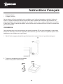
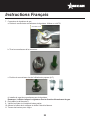
1. Shut-off de la soupape principale de gaz d’isolement et de suivre le lock-out / procédure de tag-out.
2. Tirez-out et de supprimer tous les cadrans.
Retirez le bac pour la facilité d’accès.
Tray
Knob
Bouton
Plateau

20
Instructions Français
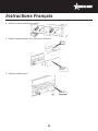
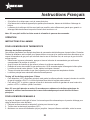
3. Retirez les vis du panneau de contrôle.
4. Retirez le panneau arrière et un écrou pour U brûleurs.
5. Retirez les brûleurs en U.
Back-Panel
Nut
Écrou
Panneau
Arrière
U Burner
U Burner
La page est en cours de chargement...
La page est en cours de chargement...
La page est en cours de chargement...
La page est en cours de chargement...
La page est en cours de chargement...
La page est en cours de chargement...
La page est en cours de chargement...
La page est en cours de chargement...
La page est en cours de chargement...
La page est en cours de chargement...
La page est en cours de chargement...
La page est en cours de chargement...
La page est en cours de chargement...
La page est en cours de chargement...
La page est en cours de chargement...
La page est en cours de chargement...
-
 1
1
-
 2
2
-
 3
3
-
 4
4
-
 5
5
-
 6
6
-
 7
7
-
 8
8
-
 9
9
-
 10
10
-
 11
11
-
 12
12
-
 13
13
-
 14
14
-
 15
15
-
 16
16
-
 17
17
-
 18
18
-
 19
19
-
 20
20
-
 21
21
-
 22
22
-
 23
23
-
 24
24
-
 25
25
-
 26
26
-
 27
27
-
 28
28
-
 29
29
-
 30
30
-
 31
31
-
 32
32
-
 33
33
-
 34
34
-
 35
35
-
 36
36


Omcan CE-CN-G48TPF Manuel utilisateur
- Taper
- Manuel utilisateur
- Ce manuel convient également à
dans d''autres langues
- English: Omcan CE-CN-G48TPF User manual
Documents connexes
-
Omcan 10865 Manuel utilisateur
-
-
-
-
Omcan 350 Manuel utilisateur
-
-
-
Omcan PT-CN-0390 Refrigerated Prep Tables Manuel utilisateur
-

