Genie GCL-J / GCL-H Guide d'installation
- Catégorie
- Porte de garage
- Taper
- Guide d'installation
Ce manuel convient également à

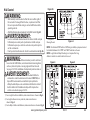
Standard Duty Operator
GCL-J
&
H
™
JACKSHAFT/HOIST
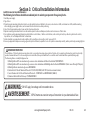
PROPER APPLICATION
ALL TYPES
Jackshaft/Hoist
Hood Mount or
Wall Mount
Door Type Operator Type HP/Max Door Weight HP/Max Door Weight
(Sectional) (Rolling Steel)
1/2HP = 1120 lbs
3/4HP = 1370 lbs
1HP = 1620 lbs
1/2HP = 998 lbs
3/4HP = 1220 lbs
1HP = 1440 lbs
NOT FOR RESIDENTIAL USE
This Installation Manual provides the information required to install, troubleshoot and
maintain the GCL-J&H
™
Commercial / Industrial Door Operator.
111845.502351 04-14
MultiVolt®
EZ Limit®
TensiBelt®

THIS PAGE LEFT BLANK

TOC
............... . . . . . .
............... . . . . .
Table of Contents
Section 1 How to use this manual . . . . . . . . . . . . . . . . . . . . . . . . . . . . . . . 1.1
Section 2 Safety Information & Instructions . . . . . . . . . . . . . . . . 2.1-2.2
Section
3
Critical
Installation
Information . . . . . . . . . . . . . . . . . . . 3.1-3.5
Section 4 Installation . . . . . . . . . . . . . . . . . . . . . . . . . . . . . . . . . . . . . . 4.1-4.8
Rolling Steel Front of Hood...................... . . 4.1-4.2
Sectional Chain Couple . . . . . . . . .................. . .
Rolling Steel Door Chart................ . . .... . . . . . . . . . 3.3
Sectional Door Chart. ........................... . . . . . . . 3.4
Chain Hoist and Keeper ........................... . . . .
Clutch Adjustment............................ . . . . . . . .
Section 5 Wiring . . . . . . . . . . . . . . . . . . . . . . . . . . . . . . . . . . . . . . . . . . 5.1-5.14
Safety Information/ Line Votage Wiring . . . . . . . . . . . . . 5.1-5.2
Low Voltage Control Wiring....................... . . . . . 5.3
External Wire Diagram ........................... . . . . . . 5.4
Wall Control ............................. . . . . . . . . . . . . . . 5.5
Interlock Switches (Rolling Steel) . . . . 5.6
Interlock Switches (Sectional) . . . . 5.7
Photocell Wiring............................... .
. . . . . . . 5.8
Sensing Edge Wiring . .......................... . .
5.9-5.10
External Radio ............................. . . . . . . . . . . 5.11
Motor Connection/Safety Information.......... . 5.12-5.14
Section 6 Operator Setup Procedures . . . . . . . . . . . . . . . . . . . . . . . . 6.1-6.10
Setting Close Direction............................ . . . . . . . . 6.2
Setting Braking Rate ............................ . . . . . . . . . . 6.3
Setting Travel Limits............................ . . . . . . . . . .
............................ . . . . ... . . .
6.4
Setting Limit Overrun ............................ . . . . . . . . . 6.5
Monitored Reversing Devices................... . . ...... . 6.10
Setting Open & Close Modes ........................... . . . 6.6
(Optional) Transmitter Programming .................. . . .
. 6.7
Setting Mid-Stop Limit ........................... . . . . . . . . . 6.8
Resetting the MRT. . 6.9
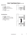
Section 7 Special Operational Features. . . . . . . . . . . . . . . . . . . . . 7.1-7.2
Operator Cycle Count .......................... . . . . . . . 7.1
GDO & Display Firmware . . . . . . . . . . . . . . . . . . . . . . . . . . . . . . 7.1
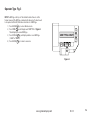
Operator Type .............................. . . . . . . . . . . 7.2
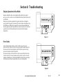
Section 8 Troubleshooting . . . . . . . . . . . . . . . . . . . . . . . . . . . . . . . . 8.1-8.5
Display Operation.............................. . . . . . . . 8.1
Error Codes .............................. . . . . . . . . . 8.1-8.2
Run Codes .............................. . . . . . . . . . . 8.2-8.3
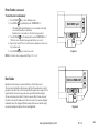
LED Indicators ............................. . . . . . . . . . . . 8.4
Safe-T-Beam® Self-Diagnostic Troubleshooting Chart . . 8.5
Section 9 Service & Maintenance . . . . . . . . . . . . . . . . . . . . . . . . . . . . . . 9.1
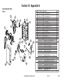
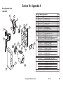
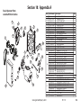
Section 10 Appendixes . . . . . . . . . . . . . . . . . . . . . . . . . . . . . . . . . . 10.1-10.13
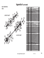
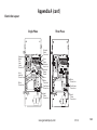
Appendix A ............................. . . . . . . . . 10.1-10.9
Operator Parts Breakdown-Hoist. . . . . . . . . . . . . . . . . .10.1
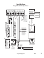
Base Electric
Section 11 Warranty . . . . . . . . . . . . . . . . . . . . . .
. . . . . . . . . . . . . . . . . . . .11.1
Operator Parts Breakdown Jackshaft . . . . . . . . . . . . . .10.2
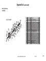
Operator Parts Breakdown Hoist/Jackshaft Combo
. .10.3
4.4-4.6
4.8
4.7
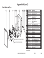
Box Parts Breakdown . ............ . . .10.8
Electric Box Layout ....................... . . . . . . . .10.9
Appendix B ............................... . . . . . . . . 10.10
Screw Terminal Assignments ................. . 10.10
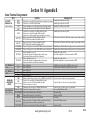
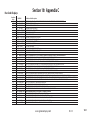
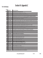
Appendix C .......................... . . . . . . . . .10.11-10.13
Run Codes .............................. . . . . . . . . 10.11
Error Codes....................... . . . . . . . . 10.12-10.13
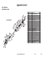
Shaft Parts Breakdown Hoist. . . . . . . . . . . . . . . .... . . .10.5
Shaft Parts Breakdown Jackshaft . . . . . . . . . . . . . . . . . .10.6
Shaft Parts Breakdown Hoist/Jackshaft Combo. . . . .10.7
Rolling Steel Wall Mount............................. . . 4.3
04-14
Alternate Motor Options . . . . . . . . . . . . . . . . . . . . . . . . .
. .10.4

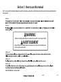
Section 1: How to use this manual
The 11 sections of this Installation Manual provide the information required to install, troubleshoot and maintain this commercial/industrial
door operator.
Section 2
Section 3
Sections 4-6
FOR ASSISTANCE CALL 1-800-843-4084.
Sections 7-8
Sections 9-11
1.1
04-14
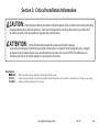
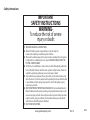
Failure to correctly perform all steps in sections 4-6 can result in serious injury or death.
WARNING
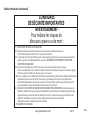
AVERTISSEMENT
Ne pas effectuer correctement toutes les étapes dans les sections 4-6 peut entraîner des
blessures graves voire la mort.

2.1
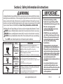
Section 2: Safety Information & Instructions
www.geniecompany.com 01-14
WARNING
Commercial/Industrial Sectional and Rolling Steel Doors are large, heavy objects that move with the help of springs
under high tension and electric motors. Since moving objects, springs under tension, and electric motors can cause
injuries, your safety and the safety of others depend on you reading the information in this manual. If you have any
questions or do not under stand the information presented, call your nearest service representative. For the number
of your local Genie® Dealer, call 800-OK-GENIE, and for Genie® Factory Technical Advice, call 800-843-4084.
In this Manual, the words Danger, Warning, and Caution are used to stress important safety information. The word:
DANGER
indicates an imminently hazardous situation which, if not avoided, will result in death or serious injury.
WARNING
indicates a potentially hazardous situation which, if not avoided, could result in death or serious injury.
CAUTION
indicates a potentially hazardous situation which, if not avoided, may result in injury or property damage.
The word NOTE is used to indicate important steps to be followed or important considerations.
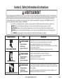
IMPORTANT
READ PRIOR TO ANY DOOR OPERATION
POTENTIAL HAZARD EFFECT PREVENTION
Do Not operate unless the doorway is in sight and free of
obstructions. Keep people clear of opening while door is moving.
Do Not allow children to play with the door operator.
Do Not change operator control to momentary contact unless an
external reversing means is installed.
Do Not operate a door that jams or one that has a broken spring.
Could result in
Serious Injury
or Death
Turn off electrical power before removing operator cover.
When replacing the cover, make sure wires are not pinched or near
moving parts.
Operator must be electrically grounded.
Do Not try to remove, repair or adjust springs or anything to which
door spring parts are fastened, such as, wood block, steel bracket,
cable or any other structure or like item.
Repairs and adjustments must be made by a trained service
representative using proper tools and instructions.
HIGH SPRING TENSION
WARNING
MOVING DOOR
1. Read manual and warnings carefully.
2. Keep the door in good working condition.
Periodically lubricate all moving parts of door.
3. If door has a sensing edge, check
operations monthly. Make any necessary
repairs to keep it functional.
4. AT LEAST twice a year, manually operate
door. The Door should open and close freely.
If it does not, the door must be taken out of
service and a traine
d service representative
must correct the condition causing
the malfunction.
5. The Operator Motor is protected against
overheating by an internal t
hermal protector.
If the operator ceases to function because
motor protector has tripped, a trained service
technician may need to correct the condition
which caused the overheating. When motor
has cooled, thermal protector will
automatically
reset and normal operation can
be resumed.
6. In case of power failure, the door can be
operated manually by pulling the release
cable to disconnect the operator drive system.
7. Keep instructions in a prominent location
near the pushbutton.
Could result in
Serious Injury
or Death
WARNING
Could result in
Serious Injury
or Death
WARNING
ELECTRICAL SHOCK

2.2
Section 2: Safety Information & Instructions
www.geniecompany.com 04-14
AVERTISSEMENT
Les portes de garage commerciales/industrielles à sections et en acier roulantes sont de gros objets lourds qui fonctionnent à l’aide de ressorts soumis à une haute tension et
de moteurs électriques. Dans la mesure où les objets en mouvement, les ressorts sous tension et les moteurs électriques peuvent entraîner des blessures, votre sécurité et celle
des autres exigent que vous preniez connaissance des informations stipulées dans ce manuel. Si vous avez des questions ou si vous ne comprenez pas les informations
ci-incluses, veuillez contacter le représentant de service le plus près. Pour obtenir le numéro du revendeur Genie® local, appelez le +1 (800)-OK-GENIE, et pour obtenir
des conseils techniques de l'usine Genie®, appelez le +1 (800)-843-4084.
Dans ce manuel, les mots Danger, Avertissement, et Attention sont utilisés pour faire ressortir d’importantes informations relatives à la sécurité. Le mot :
DANGER
signale une situation dangereuse imminente qui si elle n'est pas évitée, risque d'entraîner des blessures graves, voire mortelles.
Le terme REMARQUE est utilisé pour signaler les étapes importantes à suivre ou d’importants éléments à prendre en considération.
DANGER POTENTIEL
EFFET
PRÉVENTION
Utiliser uniquement si la porte est en vue et libre de tout obstacle. Ne laisser personne
se tenir dans l’ouverture de la porte pendant qu’elle est en mouvement.
Ne pas permettre aux enfants de jouer avec l’opérateur de la porte.
Ne pas modifier la commande de l'opérateur à contact momentané à moins qu'un moyen
d'inversion externe soit installé.
Ne pas faire fonctionner une porte qui bloque ou dont le ressort est cassé.
Pourrait entraîner
des blessures
graves voire la mort
AVERTISSEMENT
Pourrait entraîner
des blessures
graves voire la mort
CHOC ÉLECTRIQUE
TENSION ÉLEVÉE DU RESSORT
PORTE EN MOUVEMENT
ATTENTION
signale une situation potentiellement dangereuse qui, si elle n'est pas évitée, risque d'entraîner des blessures ou des dommages matériels.
AVERTISSEMENT
signale une situation potentiellement dangereuse qui, si elle n'est pas évitée, risque d'entraîner la mort ou des blessures graves.
Pourrait entraîner
des blessures
graves voire la mort
Couper le courant avant d’enlever le couvercle de l'opérateur.
Lorsque le couvercle doit être remplacé, s’assurer que les fils ne sont ni
coincés ni près des pièces mobiles.
L’opérateur doit être correctement mis à la terre.
Ne pas essayer d’enlever, réparer ni ajuster les ressorts ou toute autre pièce à laquelle le
ressort de la porte est attaché, y compris blocs de bois, supports en acier, câbles ou autres
articles semblables.
Les réparations et les réglages doivent être effectués par technicien qualifié qui se sert
d’outils appropriés et qui respecte les instructions.
AVERTISSEMENT
AVERTISSEMENT

3.1
www.geniecompany.com 04-14
Job
Site Issues to Consider/Concerns
The following list of items should be considered prior to selecting an operator for a given job site.
1-Available power supply.
2-Type of door.
3-Potential operator mounting obstructions. Items to consider include, but are not limited to: side room, room above door shaft,
room below door shaft, available mounting
surface integrity, power supply location, and convenient chain hoist and release cable positioning.
4-Size of door for appropriate
operator torque and door travel speed selection.
ssenitsud ,ssenpmad dna noitacol rotarepo edulcni redisnoc ot smetI .tnemnorivne gnitnuom rotarepO-5
and corrosiveness of the location.
6-Door activation needs/requirements. Examples include 3
button control stations, 1 button control stations, radio controls, pull
cords,
loop detectors, photoelectric controls,
key switches, etc. See “Entrapment Protection” section below.
7-Interlock switches are required under certain conditions for
6-5.7..5 egap eeS .skcol rood dna srood ssap htiw srood
rof deriuqer( smaeb llecotohp
ro/dna segde gnisrever era selpmaxE .tnempiuqe yrosseccA-8
.cte ,sthgil gninraw ,syaler lortnoc yrailixua,),tcatnoc yratnemom sa etarepo ot tes srood
Section
3:
Critical
Installation
Information
ENTRAPMENT PROTECTION
The installation of a fail safe external reversing device (such as a monitored reversing edge or photocell system, etc.) is required on all momentary contact electronically
operated commercial doors. If such a reversing device is not installed, the operator will revert to a constant contact control switch for operation (Closing only).
The Reversing Devices currently UL Approved are:
MillerEdge ME and MT series monitored edge sensors used in combination with Timer-Close Module P/N OPABTCGX.S
MillerEdge ME and MT series monitored edge sensors used in combination with MillerEdge Interface Module OPAKMEIGX.S. (Direct connect through STB inputs.)
4)
Residential Safe-T-Beam® Monitored Photocells - P/N 37220R (GSTB-BX) & 38176R.S (includes extension brackets).
5)
Series II Commercial Safe-T-Beam® Monitored Photocells - P/N OPAKPE.S and OPAKPEN4GX.S (NEMA 4).
1)
2)
6) Monitored Retro-Reflective Photoeye - P/N OPGAKRPEN4X.S
MillerEdge Wireless monitored edge sensor OPAKMMWE.S.
3)
WARNING:
DO NOT apply line voltage until instructed to do so.
AVERTISSEMENT:
NE PAS mettre sous tension tant que l'instruction n'est pas donnée de le faire.

3.2
www.geniecompany.com 04-14
Section
3: Critical Installation Information
CAUTION:
Check working condition of door before installing the operator. Door must be free from sticking and binding.
If equipped, deactivate any door locking device(s). Door repairs and adjustments, including cables and spring assemblies MUST
be made by a trained service representative using proper tools and instructions.
ATTENTION:
Vérifiez l'état de fonctionnement de la porte avant d'installer l'opérateur.
La porte doit pouvoir bouger librement et ne pas coincer. Désactivez tous les dispositifs de verrouillage de la porte (si équipés).
Les réparations et les réglages de porte, plus particulièrement pour les câbles et les ressorts DOIVENT être effectués par un
technicien qualifié qui se sert d’outils appropriés et qui respecte les instructions.
Mult
— Offers all (available) voltage combinations in both single, and 3-phase units.
E
TensiBelt
®
Z Limit
®
— F
— Employs a self-adjustment feature for tensioning.
eatures patent pending electro-mechanical design that sets limits through the control panel that are maintainable even through a power outage.
New Features:
MultiVolt
®

ENTRAPMENT
PROTECTION
The operator can be used with the following UL Approved entrapment devices in compliance with UL325 requirements active starting August 29, 2010.
UNTIL ONE OF THESE MONITORED EXTERNAL ENTRAPMENT DEVICES IS INSTALLED, THE OPERATOR WILL NOT ALLOW MOMENTARY CONTACT OPERATION IN THE CLOSE DIRECTION.
Section
3: Critical Installation Information
3.3
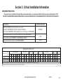
Model HP
FireStar® 3” SLAT
FireStar® 3” SLAT
INSULATED
SHEET DOOR
16GA. 18GA. 20GA. 22GA. 24GA. 26GA. 18GA. 20GA. 22GA.
ALUM. STL/SST 20GA. 22GA.
350 240 N/A
N/A
N/A
N/A
N/A
N/A
N/A
STEEL, NON-INSULATED STEEL, INSULATED
UL
L is ted
FireStar® 2” SLATGRILLESCOUNTER DOOR
ALUM. STL/SST
126 126
Rolling Steel Door Chart (sq. ft.)
Note: Total door weight and not square footage is the critical factor in selecting the proper operator. These Sq.Ft. measurements are based on square doors, e.g. 16' x 16'.
Unbalanced Fire Shutters have a maximum square footage of 52 for 22GA. steel and 42 for 20GA. steel.
GCL-J&H™ 1/2 YES
GCL-J&H™ 3/4 YES
GCL-J&H™ 1 YES
www.geniecompany.com 04-14
297 333 333 416 476 476 238 238 274
450 310 N/A
126 126
359 419 419 552 618 N/A 276 276 309
610 450 N/A
126 126
388 461 461 606 621 N/A 297 297 382
16GA. 18GA. 20GA. 22GA.
N/A N/A N/A
20GA. 22GA. 26GA.
N/A N/A 256
N/A N/A N/A
N/A N/A N/A
N/A N/A N/A
N/A N/A N/A
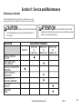
Miller Edge ME & MT series monitored edge sensors used in
combination with OPABTCGX.S Timer-Close Module or MillerEdge
Interface Module OPAKMEIGX.S. Miller Edge Wireless monitored edge sensor OPAKMMWE.S
ANY WIDTH
Residential Safe-T-Beams® P/N 37220R (GSTB-BX) and 38176R.S (includes ext. brkt’s)
Commercial Photoeye Kit P/N OPAKPE.S and OPAKPEN4GX.S (NEMA 4)
LISTED DEVICES
ALLOWABLE DOOR WIDTH
30 FEET
35 FEET
Monitored Retro-Refective Photoeye Kit P/N OPGAKRPEN4X.S

Type
Mounting
Max.
Door
Weight
(Lbs)
16GA.
Flush
Steel
16GA.
Flush
Steel
Insulated
20GA.
Ribbed
Steel
20GA.
Ribbed
Steel
Insulated
24GA.
Ribbed
Steel
24GA.
Ribbed
Steel
Insulated
Nominal
24GA.
Ribbed
Steel
Nominal
24GA.
Ribbed Steel
Insulated
Insulated
PU/FIP
Insulated
PU/FIP
1.38"
1/8" Glass
1.38"
Glass
1.38"
Insulated
PU/FIP
2"
Insulated
PU/FIP
2"
20GA.
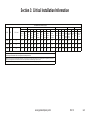
Yes TSC 1120 256 220 370 256 440 340 320 320 256 360 400 300 400 380 360 240
TSC 1370 330 256 440 310 530 400 320 320 256 450 450 370 460 440 400 330
TSC 1620 380 280 500 370 570 410 320 320 256 480 480 420 500 480 400 400
Yes
Yes
S=Jackshaft,SideMount
C=Jackshaft,CenterMount
UL L is tedHPModel
T=Trolley
Aluminum
Door S eries ->
Section 3: Critical Installation Information
3.4
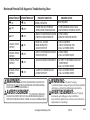
Note: Total door weight, and not the square footage, is the critical factor in selecting the proper operator.
Square footage measurements are based on "square doors." (Example=16' x 16')
NOTE: Doors that require special windloading and wide doors, normally require increased strutting (reinforcement). Strutting doors can significantly increase door
weight beyond weight shown. Consult Customer Service for the impact of wind load andstrutting on square foot limits.
NOTE: "PU-FIP" stands for "polyurethane, foamed-in-place." If no notation is present, insulation is "polystyrene, layed-in-place."
Sectional Door Chart (sq. ft.)
GCL-J&H™ 1/2
GCL-J&H™ 3/4
GCL-J&H™ 1
www.geniecompany.com 04-14
216 216 ins. 220 220 ins. 2415 2415 ins. 2411 2411 ins. 125 150 200 200-20 5150 5200 451 452
CommercialSteelInsulated&Non-Insulated Thermospan Thermomark
Exterior
Insulated
PU/FIP
Raised
Panel
1.38"
Insulated 1/4" or 1/2"
PU/FIP
Raised
Panel
2"

3.5
www.geniecompany.com 04-14
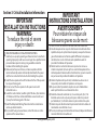
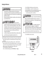
IMPORTANT
INSTALLATION INSTRUCTIONS
WARNING-
To reduce the risk of severe
injury or death:
READ AND FOLLOW ALL INSTALLATION INSTRUCTIONS.
Install only on a properly operating and balanced door. A door that is
operating improperly could cause severe injury. Have qualified service
personnel make repairs to cables, spring assemblies and other
hardware before installing the operator.
Remove all pull ropes and remove, or make inoperative, all locks
(unless mechanically and/or electronically interlocked to the power
unit) that are connected to the door before installing the operator.
Install the door operator at least 8 feet above the floor if the operator
has exposed moving parts.
Do not connect the door operator to the power source until
instructed to do so.
Locate the control station: (a) within sight of the door, (b) a minimum
of 5 feet above the floor so that small children cannot reach it, and
(c) away from all moving parts of the door.
Install the Entrapment Warning Placard next to the control station
and in a prominent location.
For products having a manual release, instruct the end user on the
operation of the manual release.
IMPORTANT
INSTRUCTIONS D’INSTALLATION
AVERTISSEMENT-
Pour réduire les risques de
blessures graves ou de mort :
1)
LIRE ET RESPECTER TOUTES LES INSTRUCTIONS D'INSTALLATION.
2)
Installez uniquement sur une porte fonctionnant correctement et bien
équilibrée. Une porte qui fonctionne mal peut provoquer des blessures
graves. Demandez à un technicien qualifié d'effectuer les réparations
des câbles, des ressorts et de toute autre quincaillerie avant de
procéder à l'installation de l'opérateur.
Retirez toutes les cordes de traction ainsi que tous les verrous ou
rendez-les inopérants (à moins qu'ils ne soient mécaniquement et/ou
électroniquement interverrouillés à l'unité motrices) qui sont connectés
à la porte avant de procéderà l'installation de l'opérateur.
Installez l'opérateur de la porte à 2,4 m minimum au-dessus du sol
lorsque des pièces mobiles de l'opérateur sont exposées.
Ne pas raccorder l'opérateur de la porte à la source d’alimentation
avant que l'instruction ne soit donnée de le faire.
Installez la station de commande : (a) en vue de la porte, (b) à 1,5 m
minimum au-dessus du sol pour que les jeunes enfants ne puissent
pas l'atteindre, et (c) à l'écart de toutes les pièces mobiles de la porte.
Installez le poster d'avertissement de pincement à côté de la station de
commande à un endroit bien en vue.
Pour les produits ayant un déclenchement manuel, indiquez à l'utilisateur
comment déclencher manuellement.
3)
4)
5)
6)
7)
8)
1)
2)
3)
4)
5)
6)
7)
8)
Section 3: Critical Installation Information

www.geniecompany.com 01-14 4.1
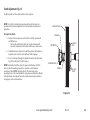
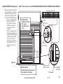
The Rolling Steel Door Operator can be assembled for right-hand or
left-hand (Each model can also be
Section 4: Installation
Rolling Steel Doors
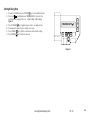
Front of Hood Installation
1) Remove wall mount brackets from operator. Attach rolling steel mounting
brackets to the operator using the fasteners provided.
Figure 1.
Figure 1
NOTE:
On Jackshaft units, release cable must be installed on operator
before unit is installed.
mounting Front of Hood.
wall mounted.) Typical mounting arrangements are shown.
2) Attach Operator to Powerhead Support bracket using the fasteners
provided. Figure 2.
5/16-18 X 3/4 CARRIAGE BOLT
& 5/16-18 FLANGE NUT
(QTY 6 EACH)
ROLLING STEEL
MOUNTING BRACKETS
Figure 2
5/16-18 X 1-1/4
CARRIAGE BOLT
(QTY 4 EACH)
USE THIS SET
OF HOLES
5/16-18 FLANGE NUT
(QTY 4 EACH)
USE THIS SET
OF HOLES
POWER HEAD SUPPORT
BRACKET

www.geniecompany.com 01-14 4.2
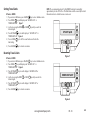
Front of Hood Installation (continued)
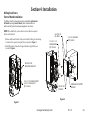
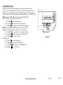
1) Install 12T #50 sprocket on operator output shaft.
2) Align keyways and insert ket into sprocket. Do not tighten set
screw at this time.
5) Assemble #50 chain using master link.
6) Align the door sprocket and operator output sprocket and
wrap #50 roller chain around both. Lock sprockets in place
by tightening their set screws.
7) Tension the drive chain using the slots in the powerhead
support bracket.
8) Tighten all mounting bracket hardware.
Figure 3
Chain Installation
(Figure 3)
#50 Drive Chain
3) Install #50 sprocket on door shaft.
4) Align keyways and insert ket into sprocket. Do not tighten set
screw at this time.

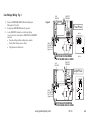
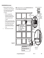
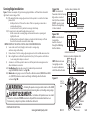
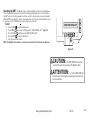
www.geniecompany.com 01-14 4.3
Rolling Steel Doors
Wall Mount Installation
Figure 4.
1) Install 12T #50 sprocket on operator output shaft.
2) Align keyways and insert key into sprocket. Do not tighten set
screw at this time.
5) Assemble #50 chain using master link.
6) Align the door sprocket and operator output sprocket and
wrap #50 roller chain around both. Lock sprockets in place
by tightening their set screws.
7) Raise or lower operator to remove slack from the chain.
Ensure operator output shaft is parallel with door shaft.
8) Secure Operator to the wall using lock down holes. Lock down
holes must be used to ensure proper chain tension.
Figure 4
LOCK DOWN HOLES
LOCK DOWN
HOLES
NOTE: Operator must be
securely fastened to the wall
using lock down holes to
ensure proper chain tension.
If using slotted mounting
holes to mount the unit, you
must use at least (2) lock
down holes in opposite
corners to firmly mount
the unit to the wall.
OPERATOR
MOUNTING
BRACKETS
NOTE: Door shaft
and operator output
shaft must be parallel
3) Install #50 sprocket on door shaft.
4) Align keyways and insert key into sprocket. Do not tighten set
screw at this time.
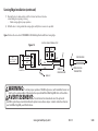
NOTE: On Jackshafts units, release cable must be installed on operator
before unit is installed.

The Operator can be assembled for right or left hand
mounting above or below the door shaft and is available with or
without hoist.
If you will be using the Tension Plate Kit shown on page 4.6, slide the
bearing plates on the operator output shaft. Assembly of the kit will be
done after the drive chain is installed.
1) Install #50 sprocket on operator output shaft.
2) Align keyways and insert key into sprocket. Do not tighten set
screws at this time.
4)
Align keyways and insert key into sprocket. Do not tighten set
screws at this time.
3)
Install #50 sprocket on door shaft.
INSTALLATION TIP:
While sprocket set screws are loose, if possible, manually operate
door to help align chain. A properly tensioned drive chain should deflect
no more than 1/2” when thumb pressure is applied mid-way between the
2 sprockets. While there is no hard and fast rule governing chain tension,
it must be tight enough to prevent clicking, popping and jumping the
teeth of the sprocket. The 1/2” guideline will insure sufficient tension.
Figure
5
4.4
www.geniecompany.com 01-14
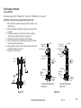
Chain Couple Installation Figure 5.
Sectional Doors
LOCK DOWN HOLES
LOCK DOWN
HOLES
OPERATOR
MOUNTING
BRACKETS
5) Assemble #50 chain using master link.
6) Align the door sprocket and operator output sprocket and
wrap #50 roller chain around both. Lock sprockets in place
by tightening their set screws.
7) Raise or lower operator to remove slack from the chain.
Ensure operator output shaft is parallel with door shaft.
8) Secure Operator to the wall using lock down holes. Lock down
holes must be used to ensure proper chain tension.
NOTE: Operator must be
securely fastened to the wall
using lock down holes to
ensure proper chain tension.
If using slotted mounting
holes to mount the unit, you
must use at least (2) lock
down holes in opposite
corners to firmly mount
the unit to the wall.
NOTE: Door shaft
and operator output
shaft must be parallel
12”-15”
CENTER
DISTANCE
OPERATOR
OUTPUT SHAFT
DOOR
SHAFT
NOTE: On Jackshafts units, release cable must be installed on operator
before unit is installed.

For Hollow Counterbalance Door Shaft:
1) Use non-threaded hole in door shaft sprocket as a guide and
drill a 3/8” diameter hole through one side of the door shaft.
Fig. 6A.
2) Insert clevis pin through sprocket and shaft to hold sprocket
in position.
3) Drill through opposite side of shaft to obtain proper hole
alignment. Fig. 6B.
4) Insert clevis pin through both holes and secure with cotter pin.
Fig. 6C.
For Solid Counterbalance Door Shaft
:
1) Insert key into door shaft keyway.
2) Slide sprocket into place and secure with set screws.
To Complete the Installation:
If needed, realign operator sprocket with door sprocket. If you have
excessive door shaft movement, an optional chain tension plate is
available. Fig. 7, pg 4.6.
Chain Couple (continued)
SPROCKET HUB
DRILL HOLE
IN THIS SIDE
OF SHAFT
DRILL HOLE IN
OPPOSITE SIDE
OF SHAFT
DOOR SHAFT
(TUBE)
DOOR SHAFT
(TUBE)
CLEVIS PIN
CLEVIS PIN
COTTER PIN
DOOR SHAFT
(TUBE)
Figure 6A
Figure 6B
Figure 6C
4.5
www.geniecompany.com 01-14

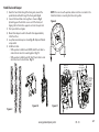
Kit available separately, P/N 111005.0001.S for 1" door shaft. 111005.0002.S for 1
1
/4" door shaft.
Installation of optional chain spreader bracket: Fig 7A & 7B
1) Place drive chain sprocket and bearing plate assembly on door
shaft as shown.
2) Place bearing plate assembly and sprocket on operator shaft
as shown.
3) Install door and operator sprockets and chain assembly as
described in preceding instructions. See page 4.4.
4) Install bolts and nuts through plates. Do not tighten.
5) Tension chain by raising or lowering the operator as needed.
Tighten operator mounting bolts.
6) Align sprockets to achieve a 90° angle between the chain and
the shafts. Tighten all set screws.
7) Tighten Tension Plate bolts.
Chain Couple (continued)
(Tension Plate Kit)
DOOR SHAFT
SPROCKET
DOOR SHAFT
CHAIN
CHAIN
TENSION
PLATE
OPERATOR
OUTPUT
SHAFT
KEY
SET SCREW
OPERATOR
SHAFT
SPROCKET
COTTER PIN
CLEVIS PIN
HOLLOW COUNTERBALANCE
DOOR SHAFT
Figure 7B
OPERATOR
SHAFT
DOOR
SHAFT
90°
Figure 7A
DOOR SHAFT
SPROCKET
DOOR SHAFT
KEY
SET SCREW
CHAIN
SET SCREW
CHAIN
TENSION
PLATE
OPERATOR
OUTPUT
SHAFT
KEY
SET SCREW
OPERATOR
SHAFT
SPROCKET
SOLID COUNTERBALANCE
DOOR SHAFT
4.6
www.geniecompany.com 01-14

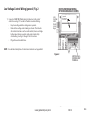
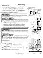
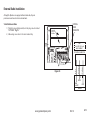
4.7
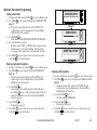
www.geniecompany.com 01-14
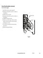
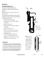
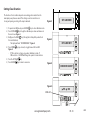
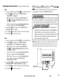
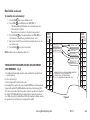
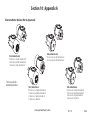
1) Route the hand chain through the chain guide, around the
pocket wheel and back through the chain guide. Fig. 8.
2) Connect the hand chain ends together as shown in Fig 9.
by twisting open the last link on one end of the chain, and
slipping the last link on the opposite end onto the open link.
3) Twist open link closed again.
4) Mount chain keeper to wall in line with chain approximately
4 feet from floor.
5) Loop chain around keeper as shown. Fig. 10. Optional Padlock
not provided.
6) Install hoist cable.
• With operator installed motor DOWN, attach hoist cable to
cam arm hole closest to mounting plate. Fig. 11.
• With operator installed motor UP, attach hoist cable to cam
arm hole closest to electric box. Fig. 11.
Hand Chain and Keeper
Figure 9
Figure 10
NOTE: To insure smooth operation, make sure there is no twist in the
hand chain before connecting the link ends together.
MOUNTED
MOTOR UP
MOUNTED
MOTOR DOWN
ATTACH
HOIST
CABLE
HERE
Figure 11
ATTACH
HOIST
CABLE
HERE
Figure 8

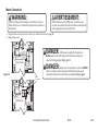
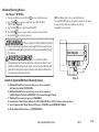
4.8
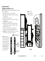
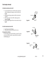
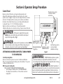
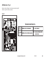
The Operators have a friction style clutch that can be adjusted.
NOTE: The clutch is intended to provide protection for the door, the
operator and associated equipment. It is not intended for entrapment
protection.
To Adjust the Clutch
1) Decrease the compression on the clutch until the operator will
not lift the door.
• Turning the adjustment castle nut counter-clockwise will
decrease compression and clockwise will increase compression.
2) Gradually increase compression until the operator will perform a
complete open and close cycle without clutch slippage.
3) Insert a cotter pin through the adjustment castle nut and bend a
leg of the cotter pin to hold it in place.
NOTE: Periodically check the system for proper clutch action. If clutch
starts to slip after working properly for some time , check manual
operation of door BEFORE adjusting clutch. The door may not be
operating freely or the counterbalance spring may need adjusting. Repairs
and adjustments must be performed by a trained service representative
using
proper tools and instructions.
Clutch Adjustment Fig. 12
CLUTCH PULLEY
WASHER
COTTER PIN
ADJUSTING NUT
CLUTCH
PAD
CLUTCH
PLATE
SPRING
www.geniecompany.com
Figure 12
01-14

5.1
Section 5: Wiring
www.geniecompany.com 04-14
WARNING
• DO NOT apply power to operator until instructed to do so.
•
It is strongly recommended, and may be required by law
in some areas, that line voltage wiring be performed by
a qualified electrician.
• Be sure that electrical power has been disconnected from
the input power wires being connected to the operator
prior to handling these wires. An appropriate lock-out/
tag-out procedure is recommended.
•
Line voltage wiring must meet all local building codes.
•
Make sure operator voltage, phase and frequency nameplate
ratings are identical to the job site line voltage ratings.
•
Input power wiring must be properly sized for the operators
amperage rating located on the nameplate.
•
To reduce the risk of electric shock, make sure the chassis of
this unit is properly grounded.
AVERTISSEMENT
• NE PAS mettre sous tension tant que l'instruction n'est
pas donnée de le faire.
•
Il est fortement recommandé voire même exigé par la loi dans
certaines régions, de contacter un électricien qualifié pour
l'acheminement du fil électrique.
• Assurez-vous que l'alimentation électrique a été déconnectée
des câbles d'alimentation d'entrée connectés à l'opérateur
avant de manipuler ces câbles. Une procédure de verrouillage/
étiquetage appropriée est recommandée.
•
Le câblage au secteur doit satisfaire à tous les codes de
construction locaux.
•
Assurez-vous que les valeurs nominales de la plaque
signalétique pour tension, phase et fréquence de l'opérateur
correspondent à celles des tensions de l'alimentation sur site.
•
La capacité d'entrée doit correspondre à la valeur nominale de
l'ampérage des opérateurs indiquée sur la plaque signalétique.
•
Pour réduire le risque de choc électrique, assurez-vous que le
châssis de l'unité est correctement mis à la terre.
La page est en cours de chargement...
La page est en cours de chargement...
La page est en cours de chargement...
La page est en cours de chargement...
La page est en cours de chargement...
La page est en cours de chargement...
La page est en cours de chargement...
La page est en cours de chargement...
La page est en cours de chargement...
La page est en cours de chargement...
La page est en cours de chargement...
La page est en cours de chargement...
La page est en cours de chargement...
La page est en cours de chargement...
La page est en cours de chargement...
La page est en cours de chargement...
La page est en cours de chargement...
La page est en cours de chargement...
La page est en cours de chargement...
La page est en cours de chargement...
La page est en cours de chargement...
La page est en cours de chargement...
La page est en cours de chargement...
La page est en cours de chargement...
La page est en cours de chargement...
La page est en cours de chargement...
La page est en cours de chargement...
La page est en cours de chargement...
La page est en cours de chargement...
La page est en cours de chargement...
La page est en cours de chargement...
La page est en cours de chargement...
La page est en cours de chargement...
La page est en cours de chargement...
La page est en cours de chargement...
La page est en cours de chargement...
La page est en cours de chargement...
La page est en cours de chargement...
La page est en cours de chargement...
La page est en cours de chargement...
La page est en cours de chargement...
La page est en cours de chargement...
La page est en cours de chargement...
La page est en cours de chargement...
La page est en cours de chargement...
La page est en cours de chargement...
La page est en cours de chargement...
La page est en cours de chargement...
-
 1
1
-
 2
2
-
 3
3
-
 4
4
-
 5
5
-
 6
6
-
 7
7
-
 8
8
-
 9
9
-
 10
10
-
 11
11
-
 12
12
-
 13
13
-
 14
14
-
 15
15
-
 16
16
-
 17
17
-
 18
18
-
 19
19
-
 20
20
-
 21
21
-
 22
22
-
 23
23
-
 24
24
-
 25
25
-
 26
26
-
 27
27
-
 28
28
-
 29
29
-
 30
30
-
 31
31
-
 32
32
-
 33
33
-
 34
34
-
 35
35
-
 36
36
-
 37
37
-
 38
38
-
 39
39
-
 40
40
-
 41
41
-
 42
42
-
 43
43
-
 44
44
-
 45
45
-
 46
46
-
 47
47
-
 48
48
-
 49
49
-
 50
50
-
 51
51
-
 52
52
-
 53
53
-
 54
54
-
 55
55
-
 56
56
-
 57
57
-
 58
58
-
 59
59
-
 60
60
-
 61
61
-
 62
62
-
 63
63
-
 64
64
-
 65
65
-
 66
66
-
 67
67
-
 68
68


Genie GCL-J / GCL-H Guide d'installation
- Catégorie
- Porte de garage
- Taper
- Guide d'installation
- Ce manuel convient également à
dans d''autres langues
Documents connexes
-
Genie GCL-GH Operator / Installation Manual
-
-
Genie GCL-T Operator / Installation Manual
-
Genie GCL-GT Operator / Installation Manual
-
-
-
-
-
-