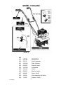
Murray 11052x4NC Instruction book
- Catégorie
- Mini motoculteurs
- Taper
- Instruction book

F–041306C
Le propriétaire doit vérifier que toutes les informations sur le produit
sont livrées avec celui-ci. Ces informations incluent : les MANUELS
D'INSTRUCTIONS, les PIÈCES DÉTACHÉES, et les CERTIFICATS DE
GARANTIE. Ces informations doivent accompagner la machine pour
assurer la conformité aux lois des États et aux lois fédérales.
INFORMATIONS SUR LE PRODUIT
lire attentivement ce livret et le conserver pour référence ultéĆ
rieure. Ce manuel renferme d'importantes informations sur
LA SÉCURITÉ, LE MONTAGE, L'UTILISATION ET L'ENTRETIEN.
CULTIVATEUR
MANUEL D'INSTRUCTIONS
El propietario debe comprobar que toda la información acerca del proĆ
ducto esté incluida con la unidad. Esta información incluye los MAĆ
NUALES DE INSTRUCCIÓN, las PIEZAS DE REPUESTOS y las GAĆ
RANTÍAS. Toda esta información debe estar incluida para asegurar
que se cumplan las leyes estatales y otras leyes aplicables.
INFORMACIÓN DEL PRODUCTO
Lea y guarde este manual para consultas futuras
Este manual contiene información importante acerca de
SEGURIDAD, ENSAMBLADO, OPERACIÓN Y MANTENIMIENTO.
CULTIVADORA
MANUAL DE INSTRUCCIONES
Modèle
11052x4NC
Modelo
11052x4NC
The owner must be certain that all the product information is included
with the unit. This information includes the INSTRUCTION BOOKS, the
REPLACEMENT PARTS and the WARRANTIES.This information must
be included to make sure state laws and other laws are followed.
PRODUCT INFORMATION
Read and keep this book for future reference.
This book contains important information on
SAFETY, ASSEMBLY, OPERATION, AND MAINTENANCE.
Model
11052x4NC
CULTIVATOR
INSTRUCTION BOOK

2
F–041306C
MURRAY, INC. Two Year Limited Warranty
Murray, Inc. warrants to the original purchaser that this unit shall be free from defects in ma-
terial and workmanship under normal use and service for a period of Two (2) Years from
the date of purchase; however, this warranty does not cover engines, accessories (such as
snow blowers, snow blades, grass baggers and plows), transmissions, batteries and Nor-
mal Wear Parts (except as noted below) or transaxles as the companies that manufacture
these items furnish their own warranties and provide service through their authorized field
service facilities. For additional information, see the warranties covering these particular
parts. If you are uncertain whether your unit contains or is equipped with one or more of
these parts, consult your dealer prior to purchase. Subject to the terms and conditions noted
in this Limited Warranty, we shall, at our option, repair or replace at no cost to the original
purchaser any part covered by this Limited Warranty during the applicable warranty period.
In the event the battery proves defective within ninety (90) days from the date of purchase,
we will replace it without charge. If the battery proves defective after (90) days but within one
hundred twenty (120) days from the date of purchase, we will replace it for a charge of one
half (1/2) of the retail price of the battery in effect at the time of return.
Normal Wear Parts are defined as belts, blades, blade adapters, pneumatic tires, headlights
and seat covers. These parts are warranted to be free from defects in material and work-
manship as delivered with the product. Any claim for repair or replacement of Normal Wear
Parts must be made within thirty (30) days of the date of purchase. No claims involving dam-
age caused from material use, abuse or misuse will be honored.
This Murray, Inc. Two (2) Year Limited Warranty is your exclusive remedy; however, this
warranty is void or does not apply to any unit that has been tampered with, altered, misused,
abused or used for rental or other commercial and/or professional (non–homeowner) uses.
Your warranty does not cover minor mechanical adjustments which are not due to any de-
fect in material or workmanship. For assistance in making such adjustments, consult your
Instruction Book.
To make a claim under this Murray, Inc. Two (2) Year Limited Warranty, return the unit (or
if authorized in advance, the defective part) along with your proof of purchase to an Autho-
rized Service Center near you. To locate the nearest Authorized Service Center, call the
Central Parts Distributor for your area shown in the list provided with your unit or check the
Yellow Page listings in your local telephone directory. If you return the entire unit, we will
repair the unit. If we authorize the return of the defective part only, we will either replace or
repair the part. In the case of a defect in a transmission or differential (as distinguished from
a transaxle), the entire transmission or differential must be returned since they do not in-
clude user serviceable parts.
This Murray, Inc. Two (2) Year Limited Warranty gives you specific legal rights, and you
may also have other rights which vary from state to state. This Limited Warranty is given
in lieu of all other expressed and implied warranties including the implied warranty
of merchantability and warranty of fitness for a particular purpose. If you need addi-
tional information on this written warranty or assistance in obtaining service, call or write to
the address below. The model number along with the CUSTOMER CARE Center 1–800
number is on the Model Number Nameplate attached to the unit.
MURRAY, INC.
Outdoor Power Equipment
Customer Service Department
P.O. Box 268
Brentwood, Tennessee 37027

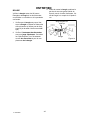
OWNER’S INFORMATION
3
F–041306C
This instruction book is written for a person with some mechanical ability. Like most service books,
not all the steps are described. Steps on how to loosen or tighten fasteners are steps anyone can
follow with some mechanical ability. Read and follow these instructions before you use the unit.
Know your product: If you understand the unit and how the unit operates, you will get the best
performance. As you read this manual, compare the illustrations to the unit. Learn the location and
the function of the controls. To help prevent an accident, follow the operating instructions and the
safety rules. Keep this manual for future reference.
IMPORTANT: Many units are not assembled and are sold in cartons. It is the responsibility of the
owner to make sure the assembly instructions in this manual are exactly followed. Other units are
purchased in an assembled condition. On assembled units, it is the responsibility of the owner to
make sure the unit is correctly assembled. The owner must carefully check the unit according to
the instructions in this manual before it is first used.
RESPONSIBILITY OF THE OWNER
The responsibility of the owner is to follow the instructions below.
1. Carefully read and follow the rules for safe operation.
2. Follow all the assembly and preparation instructions.
3. Inspect the unit.
4. Make sure that the operator of the unit knows how to correctly use all standard and accessory
equipment.
5. Operate the unit only with guards, shields, and other safety items in place and working correctly.
6. Correctly adjust the unit.
7. Service the unit only with authorized or approved replacement parts.
8. Complete all maintenance on the unit.
Engine Exhaust, some of its constituents, and
certain vehicle components contain or emit
chemicals known to the State of California to
cause cancer and birth defects or other repro-
ductive harm.
Battery posts, terminals and related accesso-
ries contain lead and lead compounds, chemi-
cals known to the State of California to cause
cancer and birth defects or other reproductive
harm. WASH HANDS AFTER HANDLING.

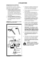
SAFETY RULES
4
F–041306C
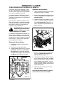
Safe Operation Practices for Cultivator
WARNING: Look for this symbol to point out important safety precautions.
It means: “Attention! Become Alert! Your Safety Is Involved.”
WARNING: To prevent acciden-
tal starting when setting–up,
transporting, adjusting or mak-
ing repairs, always disconnect spark
plug wire and put wire where it cannot
contact the spark plug .
IMPORTANT: Safety standards require opera-
tor presence controls to minimize the risk of in-
jury. Your cultivator is equipped with such
controls. Do not attempt to defeat the function
of the operator presence control under any cir-
cumstances.
Before Use
S Read the owner’s manual carefully. Be
thoroughly familiar with the controls and
the proper use of the cultivator. Know how
to stop the cultivator and disengage the
controls quickly.
S Do not operate the cultivator without wear-
ing adequate outer garments. Wear foot-
wear that will improve footing on slippery
surfaces.
S Keep the area of operation clear of all per-
sons, particularly small children and pets.
S Thoroughly inspect the area where the cul-
tivator is to be used and remove all foreign
objects.
S Keep in mind that the operator or user is
responsible for accidents or hazards occur-
ring to other people, their property, and
themselves.
S Disengage all clutches and shift into neu-
tral before starting the engine (motor).
Fuel Safety
S Handle fuel with care; it is highly flam-
mable.
S Use an approved container.
S Check fuel supply before each use, allow-
ing space for expansion as the heat of the
engine and/or sun can cause fuel to ex-
pand.
S Fill fuel tank outdoors with extreme care.
Do not smoke while refueling. Never fill fuel
tank indoors. Replace fuel tank cap se-
curely and wipe up spilled fuel.
S If fuel is spilled, do not attempt to start the
engine but move the machine away from
the area of spillage and avoid creating any
source of ignition until fuel vapors have dis-
sipated.
S Never remove the fuel tank cap or add fuel
to a running or hot engine.
S Never store fuel or cultivator with fuel in the
tank inside a building where fumes may
reach an open flame.
Operating Safety
S Never allow children or young teenagers to
operate the cultivator. Keep them away
while it is operating. Never allow adults to
operate the cultivator without proper in-
struction.
S Do not operate this machine if you are tak-
ing drugs or other medication which can
cause drowsiness or affect your ability to
operate this machine.
S Do not use this machine if you are mentally
or physically unable to operate this ma-
chine safely.
S Always wear safety glasses or eye shields
during operation or while performing an
adjustment or repair to protect your eyes
from foreign objects that may be thrown
from the cultivator.
S Do not put hands or feet near or under ro-
tating parts.
S Exercise extreme caution when operating
on or crossing gravel drives, walks, or
roads. Stay alert for hidden hazards or
traffic.
S Exercise caution to avoid slipping or falling.
S Never operate the cultivator without proper
guards, plates, or other safety protective
devices in place.
S Use only attachments and accessories ap-
proved by the manufacturer of the machine

SAFETY RULES
5
F–041306C
(such as wheel weights, counterweights,
and the like.
S Never operate the cultivator at high trans-
port speeds on hard or slippery surfaces.
Look behind and use care when backing.
S Never allow bystanders near the cultivator.
S Keep children and pets away while
operating.
S Never operate the cultivator without good
visibility or light.
S Be careful when tilling in hard ground. The
tines may catch in the ground and propel
the tiller forward. If this occurs, let go of the
handlebars and do not restrain the ma-
chine.
S Use extreme care when reversing or pull-
ing the machine towards you.
S Do not change the engine governor set-
tings or overspeed the engine.
S Start the engine or switch on the motor
carefully according to instructions and with
feet well away from the tines.
S Never pick up or carry a machine while the
engine is running.
S Do not run the engine indoors. The ex-
haust fumes are dangerous, containing
CARBON MONOXIDE, an ODORLESS
and DEADLY GAS.
S Take all possible precautions when leaving
the cultivator unattended. Stop the engine,
and if equipped, remove the key.
S Do not overload the cultivator capacity by
attempting to till too deep at too fast a rate.
Safe Storage
S Always refer to the owner’s manual instruc-
tions for important details if the cultivator is
to be stored for an extended period.
S Never store the cultivator with fuel in the
fuel tank inside a building where ignition
sources are present such as water and
space heaters, clothes dryers, and the like.
Allow the engine to cool before storing in
any enclosure.
S If the fuel tank has to be drained, do this
outdoors.
S Keep the cultivator in safe working condi-
tion. Check all fasteners at frequent inter-
vals for proper tightness.
Repair / Adjustments Safety
S After striking a foreign object, stop the en-
gine. Remove the wire from the spark plug,
and keep the wire away from the plug to
prevent accidental starting. Thoroughly in-
spect the cultivator for any damage, and
repair the damage before restarting and
operating it.
S If cultivator should start to vibrate abnor-
mally, stop engine and check immediately
for the cause. Vibration is generally a warn-
ing of trouble.
S Stop the engine whenever you leave the
operating position. Also, disconnect the
spark plug wire before unclogging the tines
and when making any repairs, adjust-
ments, or inspections.
S When cleaning, repairing, or inspecting,
shut off the engine and make certain all
moving parts have stopped.
S Never attempt to make any adjustments
while the engine is running except when
specifically recommended by the manufac-
turer.

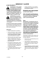
SAFETY RULES
6
F–041306C
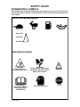
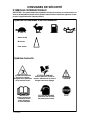
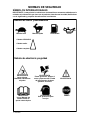
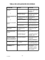
INTERNATIONAL SYMBOLS
IMPORTANT: Many of the following symbols are located on your unit or on literature sup-
plied with the product. Before you operate the unit, learn and understand the purpose for
each symbol.
Control And Operating Symbols
Slow Fast
WARNING
Thrown Objects.
Keep Bystanders Away.
WARNING
Rotating Parts. Stop Engine.
Disconnect Spark Wire Before
Making Adjustments.
IMPORTANT
Read Owner’s Manual
Before Operating
This Machine.
WARNING
STOP
WARNING
Wear Eye Protection
Safety Warning Symbols
Fuel Oil
Choke OFF
Half Choke
Full Choke

ASSEMBLY
7
F–041306C
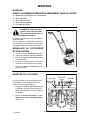
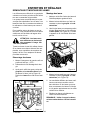
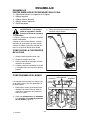
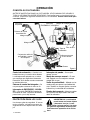
ASSEMBLY
PARTS PACKED SEPARATELY
IN CARTON
1 – Owner’s Manual (not shown)
1 – Upper Handle
1 – Right Lower Handle
1 – Left Lower Handle
1 – Parts Bag
WARNING: Always wear safety
glasses or eye shields while as
-
sembling the cultivator.
Figure 1 shows the cultivator completely as-
sembled.
References to the right or left side of the cul-
tivator are from the viewpoint of the opera-
tor’s position behind the unit.
HOW TO REMOVE THE
CULTIVATOR FROM THE CARTON
1. Remove the parts bag from the carton.
2. Remove the handles from the carton.
3. Remove the packing material positioned
around the unit.
4. Lift the cultivator out of the carton and
place on a hard level surface.
5. Remove the packing material from the
tines.
Figure 1
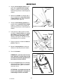
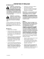
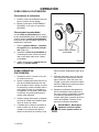
HOW TO
ASSEMBLE THE HANDLE
The lower handles have a short bend at the
bottom and have been flattened at the top.
1. Unwind the throttle control from around
the engine. Straighten the throttle cable.
Make sure that you do not bend or kink
the cable.
2. Remove the locknuts, washers, and
screws from the tine shield (see
Figure 2).
Figure 2
Locknuts
Washers
Bolts
WashersTine Shield

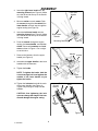
ASSEMBLY
8
F–041306C
3. Insert the right lower handle into the
mounting channel (see Figure 3). Make
sure the flat end at the top of the handle
is facing inward.
4. Mount a washer on each screw. Push
the screws through the tine shield, the
lower handle, and half way through the
engine casting (see Figure 4).
5. Insert the left lower handle into the
mounting channel (see Figure 3). Make
sure the flat end at the top of the handle
is facing inward.
6. Push the screws through the engine
casting, the lower handle, and the tine
shield. Secure with washers and lock-
nuts as shown in Figure 4. Do not tight-
en as this time.
7. Remove the fasteners from the upper
handle (see Figure 5).
8. Assemble the upper handle to the lower
handles with the fasteners.
9. Tighten the knobs.
NOTE: To tighten the knobs, hold the
curved carriage bolt head against the
outside of the lower handle as you
tighten the knobs.
10. Tighten the locknuts that hold the ends
of the lower handles (see Figure 4).
Tighten only enough to firmly hold the
handles.
CAUTION: Over tightening the lock-
nuts can change the shape of the han-
dle and damage the engine casing.
Figure 3
Left Lower
Handle
Right Lower
Handle
Mounting Channel
Screw
Washer
Washer
Locknut
Tine Shield
Figure 4
Figure 5
Carriage
Bolt
Flat Washer
Curved
Washer
Knob
Upper Handle

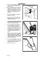
ASSEMBLY
9
F–041306C
11. Remove the shut-off switch, switch
bracket, screw, and wire harness from
the parts bag.
12. Mount the throttle control and shut-off
switch to the right handle. Secure the
eyelet, the shut-off switch, the switch
bracket and the throttle control to the
handle with the screw as shown in
Figure 6.
13. Connect the terminal to the shut-off
switch (see Figure 6).
14. Connect the other end of the wire as-
sembly to the two wires at the rear of
the engine (see Figure 7).
NOTE: If the shut-off switch wires are
not properly connected, the shut-off
switch will not stop the engine.
15. Attach the throttle control cable and
the wire assembly to the upper and
lower handle with the tie strap (see
Figure 8). Thread the pointed end of the
tie strap through the other (square) end
of the strap. Pull the tie strap tight
around the throttle cable and the lower
handle.
NOTE: One side of the tie strap is
rough, the other side is smooth. The
rough side must be on the inside of the
loop formed when the ends of the tie
strap are put together.
16. Try to loosen the tie strap. If it will loos-
en, it is put together with the smooth side
to the inside of the loop. Remove the tie
strap and reverse the direction.
17. Cut off the excess strap.
Figure 6
Throttle
Control
Screw
Eyelet
Shut-off
Switch
Switch
Bracket
Terminal
Figure 7
Wire Assembly
Figure 8
Tie Strap

ASSEMBLY
10
F–041306C
n CHECKLIST
For the best performance and satisfaction
from this quality product, please review the
following checklist before you operate the
cultivator:
n All assembly instructions have been
completed.
n Check carton. Make sure no loose
parts remain in the carton.
n All fasteners have been properly tight-
ened.
As you learn how to use the cultivator, pay
extra attention to the following important
items:
nn Fuel tank is filled with a fresh, clean,
fuel mixture.
nn Become familiar and understand the
function of all controls. Before you
start the engine, operate all controls.
IMPORTANT: This unit is equipped with an internal combustion engine and must not be
used on or near any unimproved forest–covered, brush–covered or grass–covered land
unless the engine’s exhaust system is equipped with a spark arrester meeting
applicable local or state laws (if any). If a spark arrester is used, it must be maintained in
effective working order by the operator.
In the State of California the above is required by law (Section 4442 of the California
Public Resources Code). Other states may have similar laws. Federal laws apply on
federal lands. See an Authorized Service Center for a spark arrester for the muffler.

OPERATION
11
F–041306C
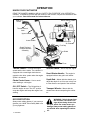
KNOW YOUR CULTIVATOR
READ THE OWNER’S MANUAL AND ALL SAFETY RULES BEFORE YOU OPERATE the
cultivator. To familiarize yourself with the location of the controls, compare the illustrations with
your cultivator. Save this manual for future reference.
Tines
Figure 9
Throttle Control
Lever
Upper Handle
Fuel Cap
Lower Handle
Depth Rod and
Transport Wheels
Assembly
Tine Shield
Choke Control
Recoil Starter Handle
Air Cleaner
Shut-off
Switch
Throttle Control – Controls the engine
speed and the tine rotation. The cultivator is
equipped with a centrifugal clutch that en-
gages the tine drive system when the engine
speed is increased.
Choke Control Lever – Use to assist
when starting a cold engine.
ON / OFF Switch – The ON position al-
lows the engine to start. The OFF position
stops the engine and keeps the engine from
starting.
Shut-off Switch – Use to stop the engine.
Recoil Starter Handle – The engine is
equipped with an easy pull recoil starter.
Depth Rod – Mount with the wheels up to
adjust the depth of cut. Also use to help con-
trol the direction and speed of the cultivator.
Transport Wheels – Mount with the
wheels down when transporting the cultiva-
tor.
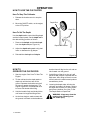
EYE PROTECTION
Always wear safety glasses. If you wear eye
glasses, put a Wide Vision Safety Mask over
your eye glasses.
WARNING: Debris thrown from
the cultivator can result in for-
eign objects being thrown into
the eyes, which can cause severe eye
damage. Always wear safety glasses or
eye shields when operating the cultiva-
tor.

OPERATION
12
F–041306C
HOW TO USE THE CULTIVATOR
How To Stop The Cultivator
1. Release the throttle control to stop the
tines.
2. Move the ON/OFF switch, on the engine,
to the OFF position.
How To Set The Depth
Use the depth rod to control the tilling depth
and the forward speed. Set the depth rod to
the desired tilling position as follows:
1. Remove the hairpin and the clevis pin
from the depth rod (see Figure 10).
2. Adjust the depth rod upward to dig shal-
lower or downward to dig deeper.
3. Reinstall the clevis pin and hairpin.
Figure 10
Depth Rod Bracket
Clevis Pin
Depth Rod
HOW TO
OPERATE THE CULTIVATOR
1. Start the engine. See “How To Start The
Engine”.
2. Tilt the unit back on the depth stake or
depth rod until the tines are off the
ground. Squeeze the throttle control all
the way up against the hand grip. The
engine is governor controlled and must
be run at full throttle while tilling.
3. Hold the handle firmly and slowly tilt the
unit forward to begin the tilling action.
4. As the tines begin to make contact with
the ground, hold back on the handles so
that the tines will dig into the soil and not
ride forward over the ground.
5. Avoid tilling soil that is too dry as it will
pulverize and produce a dust that will not
hold water. Also, tilling soil that is too wet
will be hard on the machine and produce
unsatisfactory clods.
6. Lowering the depth stake will slow the
cultivator and make it till deeper. Raising
the depth bar will allow it to move faster
and till more shallow. See “How To Set
The Depth Stake or Depth Rod”.
WARNING: Keep away from the
rotating tines. Rotating tines
can cause injury.

OPERATION
13
F–041306C
BEFORE STARTING THE ENGINE
How To Prepare The Engine
WARNING: Always use a safety
fuel container. Do not smoke
when adding the fuel mixture to
the engine. When inside an enclosure,
do not fill the fuel tank. Before you add
the fuel mixture, stop the engine. Let the
engine cool for several minutes.
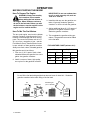
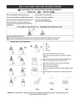
How To Mix The Fuel Mixture
The two cycle engine, used on this cultivator,
requires a mixture of gasoline and oil for lu-
brication of the bearings and other moving
parts. The correct fuel mixture ratio is 24:1
(5.3 oz. oil per one gallon of gas – see the
Fuel Mixture Chart). Gasoline and oil must
be pre–mixed in a clean gasoline container.
Always use fresh, clean, unleaded gasoline.
Mix gasoline and oil as follows:
1. Pour one (1) U.S. quart of fresh, clean,
unleaded automotive gasoline into a one
gallon size gasoline container.
2. Add 5.3 ounces of clean, high quality,
two–cycle oil to the gasoline container.
IMPORTANT: Do not use outboard mo-
tor oil or multi–viscosity oils,such as
10W–30 or 10W–40.
3. Install the fuel cap onto the gasoline con-
tainer. Vigorously shake the gasoline
container to mix the oil with the gasoline.
4. Add an additional three (3) U.S. quarts of
gasoline to the gallon container. Again
shake the gasoline container.
5. This completes the gasoline mixing pro-
cedure. The gasoline can now be added
to the fuel tank.
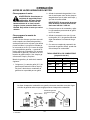
FUEL MIXTURE CHART (mixture 24:1)
U.S. SI. (Metric
GAS OIL GAS OIL
1 Gal. 5.3 oz. 4 Liters .167 L
2 Gal. 11 oz. 8 Liters .333 L
5 Gal. 27 oz. 20 Liters .833 L
Do not fill the fuel tank with gasoline that does not have oil mixed in it. Shake the
gasoline container before each filling of the fuel tank.
Shake Can
OIl
(5.3 oz)
Gasoline
1U.S.
Quart
1 U.S. Gallon container
1 U.S.
Gallon
Special
Gasoline
Add more gas
(3 U. S. Quarts)

OPERATION
14
F–041306C
HOW TO START THE ENGINE
Before you start the engine, make sure that
you have read and understand all the in-
structions on the preceding pages.
1. Fill the fuel tank to 1/2 inch below the
bottom of the fill neck. Reinstall the fuel
tank cap securely. Always use fresh fuel.
Never use fuel that could be stale from
long periods of storage.
2. Move the Shut-off switch to the ON
position (see Figure 11).
3. If the engine is cold, move the choke
control to the Full Choke position (all the
way down).
NOTE: Do not choke a hot or warm
engine.
4. Put the unit firmly on the tines and depth
stake, or wheels, in an open area.
5. Hold the right handle firmly with your left
hand.
6. Hold the rope handle with your right
hand and pull to start the engine. Repeat
if necessary. (It is sometimes necessary
to hold the throttle control lever against
the hand grip with your left hand. As
soon as the engine starts, slowly release
the throttle control. If released too slowly,
the unit will sometimes move forward).
7. When the engine starts, move the choke
lever to the Half Choke position. When
the engine runs smoothly, move the
choke lever to the No Choke position.
NOTE: If the tines do not stop when
the throttle control is released, adjust
the carburetor idle speed. For adjust-
ment of carburator, see the Engine
Manual.
8. To stop the engine, release the throttle
control and move the Shut-off switch to
the OFF position.
9. If the engine becomes flooded remove
and dry the spark plug. See “Spark Plug
Maintenance” in the Maintenance sec-
tion of this manual. Then, pull the starter
rope with the choke lever in the No Cho-
ke position.
WARNING: The muffler and sur
-
rounding areas become hot af-
ter running the engine. Avoid
these areas.
Choke Control
Recoil Starter Handle
No Choke
Half Choke
Full Choke
Air Cleaner
Figure 11
Shut-Off Switch

OPERATION
15
F–041306C
CULTIVATING TIPS
S Tilling is digging in, turning over and
breaking up packed soil before planting.
Loose unpacked soil helps root growth.
Best tilling depth is 4 to 6 inches. A tiller
will also clear the soil of unwanted vege-
tation. The decomposition of this vegeta-
tion matter enriches the soil. Depending
on the climate (rainfall and wind), it may
be advisable to till the soil at the end of
the growing season to further condition
the soil.
S Avoid tilling soil that is too dry as it will
pulverize and produce a dust that will not
hold water. Also, tilling soil that is too wet
will produce unsatisfactory clods.
S Better growth will be obtained if an area
is tilled properly and used soon after till-
ing to preserve the moisture content.
S The depth stake (on the back of the culti-
vator) serves a dual purpose. It helps
regulate the depth of the cut and also
acts as a brake to help the operator con-
trol the speed of the cultivator.
S Lowering the depth stake will slow the
cultivator and make it till deeper. Raising
the depth stake will allow it to move fast-
er and till more shallow.
S If the cultivator stops forward motion and
tries to dig deeper than necessary, move
the handles from side to side to start for-
ward motion.
S Cultivating is loosening or digging
around growing plants which allows the
plants to flourish.
S When using the cultivator to remove
weeds, it is best to cultivate no deeper
than 1–1/2 inches. Cultivating deeper will
only pull to the surface ungerminated
weed seeds. Raising the depth stake will
allow it to move faster and till more shal-
low.
S When cultivating around plants or close
areas, you may want to remove the out-
side tines. See “Tine Replacement” in
the Service/Adjustments section.
S For better control when cultivation
around delicate plants, turn over the
stake and support the cultivator with the
wheels.
WARNING: Read the Owner’s
manual. Know location and
functions of all controls. Keep
all safety devices and shields in place.
Never allow children or uninstructed
adults to operate cultivator. Shut off en-
gine before unclogging tines or making
repairs. Keep bystanders away from ma-
chine. Keep away from rotating parts
and tines. They can cause injury.
HINTS FOR DEPTH STAKE OR
WHEEL ADJUSTMENT
Light cultivation with moderate
growth
(1 to 2 inches depth)
Adjust the wheels upward to their highest or
next to their highest position. Make sure the
handles are at a comfortable height for oper-
ating the cultivator.
Seed bed preparation
(4 to 6 inches depth)
Use the depth stake. Adjust the depth stake
downward for deeper cultivation.
Heavy soil (4 inch depth or greater)
Remove the depth stake and work the tines
down with a back and forth motion to at least
a depth of 4 inches. Slowly pull the cultivator
backward allowing the soil to feed forward
over the tines.

MAINTENANCE
16
F–041306C
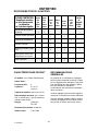
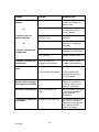
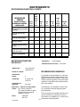
CUSTOMER RESPONSIBILITIES
SERVICE RECORDS
Fill in dates as you
complete regular
service.
Before
Each
Use
After
First
2
Hours
Every
25
Hours
Every
75
Hours
Before
Storage
Before
Each
Season
SERVICE
DATES
Tighten All Screws and
Nuts
√ √
Lubricate Tine Shaft
√ √
Lubricate Transmission
√ √
Check Spark Plug
√ √
Clean and Oil Air Cleaner
Filter
√
√
Clean Cylinder Exhaust
Ports
√
Drain Fuel
√
PRODUCT SPECIFICATIONS
Model No.: See Nameplate
Date Of Purchase:
Horse Power: 2
Displacement: 3.0 cu. in.
(49.2 cc.)
Gasoline Capacity: 20 oz.
Fuel/Oil Mix Ratio: 24:1 Oil To Gas
(5.3 oz. oil to 1 gal. gas)
(use unleaded regular)
Spark Plug: Champion
RCJ–8Y
Spark Plug Gap: 0.035 inch
Idle RPM: 1700–3000
GENERAL RECOMMENDATIONS
The warranty on this cultivator does not cov-
er items that have been subjected to opera-
tor abuse or negligence. To receive full value
from the warranty, the operator must main-
tain the cultivator as instructed in this
manual.
Some adjustments must be made periodical-
ly to properly maintain your cultivator.
All adjustments in the Service and Adjust-
ments section of this manual must be
checked at least once each season.

MAINTENANCE
17
F–041306C
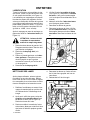
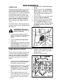
LUBRICATION
Every 25 hours and/or at the beginning of
each season, make sure the gear box is
filled with lubricant (see Figure 12). Tubes of
gear lubricant are available from most auto-
motive supply stores. Use portable tool
grease such as Lubriplate 630AA (Product
No. 06787, 1–3/4 oz. tube) or Lubriplate
GR–132 (Product No. 15892, 10 oz. tube).
After cleaning and before storage, apply oil
to the tine shaft (see Figure 12).
WARNING: Allow the transmis-
sion to cool before filling with
grease.
1. Remove both left side tines. See “How
To Replace The Tines” in the Service
and Adjustments section.
2. Remove the air vent screw (see
Figure 12).
3. Mount a grease gun onto the grease fit-
ting. Fill the transmission until the
grease begins to come out of the air vent
screw hole.
4. Reinstall the air vent screw.
5. Check the condition of the felt washer
(see Figure 12). Replace the felt wash-
er if it is damaged (see the Repair Parts
section in this manual).
6. Clean and lubricate the tine shaft with a
few drops of oil.
7. Reinstall the left side tines.
8. Remove the right side tines. Check the
felt washer for damage. Clean and oil
the tine shaft. Reinstall the right side
tines.
Figure 12
Grease Fitting
Tine
Shaft
Air Vent Screw
Felt
Washer
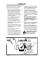
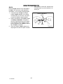
HOW TO CLEAN THE TINES
Always remove dirt and debris from the culti-
vator after each use. Remove any string,
wire or vegetation that may become lodged
in the mechanism and stop the tines from
rotating.
1. Release the throttle control and move
the on–off switch to the OFF position.
Disconnect the spark plug wire from the
spark plug.
2. While wearing gloves, remove the hair-
pins and clevis pins that secure the tine
assemblies to the shaft (see Figure 13).
Remove the tines from the shaft.
3. Remove any lodged debris from the
shaft and tines. Clean and lubricate the
tine shaft with a few drops of oil.
4. Reassemble the tines on the shaft and
secure with a clevis pin and hairpin.
5. Connect the spark plug wire to the spark
plug.
Figure 13
Clevis
Pins
Hair Pins
Tines

MAINTENANCE
18
F–041306C
SPARK PLUG
Check the spark plug every 25 hours. Re-
place the spark plug if the electrodes are
pitted or burned or if the porcelain is
cracked.
1. Make sure the spark plug is clean.
Clean the spark plug by carefully scrap-
ing the electrodes (do not sand blast or
use a wire brush).
2. Check the spark plug gap with a feeler
gauge. See “Product Specifications” for
the correct spark plug gap and replace-
ment spark plug.
3. Before installing the spark plug, coat
the threads lightly with oil for easy re-
moval. Tighten the spark plug to a torque
of 15 foot–pounds.
Figure 14
Spark Plug
Feeler Gauge
0.035”

SERVICE AND ADJUSTMENT
19
F–041306C
HOW TO REMOVE AND INSTALL THE TINES
References to the right or left side of the cul-
tivator are from the viewpoint of the opera-
tor’s position behind the unit.
All four tines are different and cannot be in-
terchanged. The tines must be correctly
installed or the cultivator will not function
properly.
To till around plants or in small areas, the
outside tines can be removed to reduce the
tilling width to approximately 7 inches.
WARNING: The tines are self
sharpening and will become
quite sharp from use. Handle
carefully.
The tines will all wear evenly. If the tines are
being replaced because of wear, we recom-
mend that all four tines be replaced at the
same time. To replace the tines, do the fol-
lowing:
Tine Removal
1. Put the on–off switch in the OFF posi-
tion.
2. Disconnect the spark plug wire from the
spark plug.
3. While wearing gloves, remove the hair-
pins and clevis pins that secure the tine
assemblies to the shaft (see Figure 15).
Remove the tines from one side of the
unit.
Figure 15
Clevis
Pins
Hair Pins
Tines
Tine Installation
1. Clean and lubricate the tine shaft with a
few drops of oil.
2. Place the inside tine on the tine shaft
and reinstall the clevis pin and hairpin.
3. When the tines are properly installed, the
letter R will be visible on the outside of
the right tine (see Figure 16). The letter
L will be visible on the outside of the left
tine.
Figure 16
R
4. Mount the outside tine on the tine shaft
and fasten with the clevis pin and hair-
pin (see Figure 15).
5. The cutting tips on the outside tines all
bend in toward the inside tine. When as-
sembled correctly, the letter R on the
right side, or L on the left side, will be
visible from the outside of the unit.
6. Repeat the above steps on the opposite
side of the unit.
NOTE: Make sure the tines are installed
on the correct side of the unit.

SERVICE AND ADJUSTMENT
20
F–041306C
STORAGE
WARNING: Never store the cul
-
tivator indoors with fuel in the
fuel tank. Never store in an en-
closed, poorly ventilated area where
fumes could reach an open flame, a
spark or a pilot light as on a furnace, wa
-
ter heater or clothes dryer.
WARNING: Do not remove gas
-
oline while inside a building,
near a fire, or while you smoke.
Gasoline fumes can cause an explosion
or a fire.
When the cultivator is put in storage for thirty
days or more, follow the steps below to
make sure the cultivator is in good condition
the following season.
Cultivator
S Completely clean the cultivator.
S Remove the tines. Clean and apply oil to
the tine shafts. Mount the tines onto the
tine shafts. See “How To Remove And
Install The Tines” in the Service And Ad-
justments section.
S Loosen the knobs that secure the upper
handle to the lower handle. Carefully fold
the upper handle. Make sure the throttle
cable is not bent. Tighten the knobs.
S The cross piece of the upper handle (be-
tween the lower handles) can now be
used as a carry handle. To store the cul-
tivator up off the floor and out of the way,
the cross piece can also be hooked over
a wall hook.
S Put the cultivator in a building that has
good ventilation.
S Cover the cultivator with a suitable pro-
tective cover that does not retain mois-
ture. Do not use plastic.
IMPORTANT: Never cover the cultivator
while the engine and exhaust areas are
still warm.
NOTE: A yearly checkup or tune–up by a
Authorized Service Center is a good way
to make sure that your cultivator will pro-
vide maximum performance for the next
season.
Engine
IMPORTANT: It is important to prevent
gum deposits from forming in fuel system
parts such as the carburetor, fuel filter,
fuel hose, and tank during storage. Also,
using alcohol–blended fuels (called gaso-
hol, ethanol or methanol) can attract
moisture which leads to separation and
formation of acids during storage. Acidic
gas can damage the fuel system of an en-
gine while in storage.
To prevent engine damage when the cultiva-
tor is in storage for 30 days or more, follow
the steps below:
S Let the engine run until it is out of gaso-
line.
S Slowly pull the starter handle until you
feel resistance due to compression in
the cylinder, then stop.
S Slowly release the starter rope. This
position will close both the intake and the
exhaust ports and help prevent corrosion
of the piston and cylinder.
La page charge ...
La page charge ...
La page charge ...
La page charge ...
La page charge ...
La page charge ...
La page charge ...
La page charge ...
La page charge ...
La page charge ...
La page charge ...
La page charge ...
La page charge ...
La page charge ...
La page charge ...
La page charge ...
La page charge ...
La page charge ...
La page charge ...
La page charge ...
La page charge ...
La page charge ...
La page charge ...
La page charge ...
La page charge ...
La page charge ...
La page charge ...
La page charge ...
La page charge ...
La page charge ...
La page charge ...
La page charge ...
La page charge ...
La page charge ...
La page charge ...
La page charge ...
La page charge ...
La page charge ...
La page charge ...
La page charge ...
La page charge ...
La page charge ...
La page charge ...
La page charge ...
La page charge ...
La page charge ...
La page charge ...
La page charge ...
La page charge ...
La page charge ...
La page charge ...
La page charge ...
-
 1
1
-
 2
2
-
 3
3
-
 4
4
-
 5
5
-
 6
6
-
 7
7
-
 8
8
-
 9
9
-
 10
10
-
 11
11
-
 12
12
-
 13
13
-
 14
14
-
 15
15
-
 16
16
-
 17
17
-
 18
18
-
 19
19
-
 20
20
-
 21
21
-
 22
22
-
 23
23
-
 24
24
-
 25
25
-
 26
26
-
 27
27
-
 28
28
-
 29
29
-
 30
30
-
 31
31
-
 32
32
-
 33
33
-
 34
34
-
 35
35
-
 36
36
-
 37
37
-
 38
38
-
 39
39
-
 40
40
-
 41
41
-
 42
42
-
 43
43
-
 44
44
-
 45
45
-
 46
46
-
 47
47
-
 48
48
-
 49
49
-
 50
50
-
 51
51
-
 52
52
-
 53
53
-
 54
54
-
 55
55
-
 56
56
-
 57
57
-
 58
58
-
 59
59
-
 60
60
-
 61
61
-
 62
62
-
 63
63
-
 64
64
-
 65
65
-
 66
66
-
 67
67
-
 68
68
-
 69
69
-
 70
70
-
 71
71
-
 72
72


Murray 11052x4NC Instruction book
- Catégorie
- Mini motoculteurs
- Taper
- Instruction book
dans d''autres langues
- English: Murray 11052x4NC
- español: Murray 11052x4NC
Documents connexes
Autres documents
-
Simplicity 11054X37NB Manuel utilisateur
-
Southland SCV43 Manuel utilisateur
-
EarthQuake MC43 CULTIVATOR 43CC 2CYC 10IN WIDE 7IN WHEEL Manuel utilisateur
-
Jonsered CT 2105 R Le manuel du propriétaire
-
-
Homelite UT60526 Manuel utilisateur
-
Maxim 23039SWSN Guide d'installation
-
-
 Bush Furniture A177872B Assembly Manual
-
 BOND MANUFACTURING 67322 Manuel utilisateur

