
1
Note: This kit must be installed or serviced by a qualifi ed installer, service agency or gas supplier.
These instructions are to be used in conjunction with the main installation instructions for the above
listed models.
WARNING: If these instructions are not followed exactly, a fi re or explosion may result
causing property damage, personal injury or loss of life.
GROUNDING: This power supply must be installed and grounded in accordance with local codes,
or in the absence of local codes, with the current Canadian Electrical Code CSA C22.1. or in the
USA the National Electrical Code ANSI/NFPA70 latest edition.
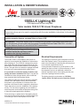
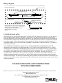
Description of System
The models 1500 & 1700 fi replaces have been de-
signed to accommodate the installation of a decorative
accent lighting kit. The 1565LLK is designed to project
light upward through the narrow gap between the rear
panel and the horizontal base platform surrounding the
burner. The light eff ect is intended to highlight the fl uted
liner sets (not recommended with the glass liners).
It is preferable to install the lighting kit before com-
pleting the heater installation although it may also be
retrofi tted at a later date provided a power outlet has
been prewired within the fi replace casing.
The 1565LLK Lighting Kit requires a power receptacle
located within the fi replace casing. We recommend
that power to the receptacle be controlled via a wall
mounted on/off dimmer switch (supplied by electrician).
These instructions cover the installation of the lighting
kit only. For instructions regarding how and where to
locate the power outlet within the fi replace casing refer
to instructions packaged with the fi replace.
Future servicing or replacement of the lighting may be
done through the window aperture of the fi replace with-
out needing to remove the fi replace from the wall.
1565LLK Lighting Kit
CSA approved for use only with
Valor models 1500 & 1700 Linear Fireplaces
4003001-03
© 2018, Miles Industries Ltd. All rights reserved.
Electrical Requirements
This lighting kit requires a power receptacle mounted
within the fi replace casing. The receptacle power will
need to be controlled by a wall dimmer switch as there
is no controller supplied with this kit.
If using a duplex receptacle to provide power for the
ambient fan option as well, it will be necessary to “split”
the receptacle and run an additional conductor to
maintain separate control of the lighting and fan (see
instructions packaged with the heater).
The lighting electrical requirements are 120 Volts,
1 phase, 60 Hz. Full load current of less than 2 amps.
NOTE: Electrical wiring must be already
installed inside the appliance case to
complete the lighting installation.
INSTALLATION & OWNER’S MANUAL
L1 & L2 Series

2
Considerations
We recommend installing this lighting kit to the
appliance before completing the installation of the
appliance.
If installing this kit after the fi replace installation has
been completed, remove the following components
using the fi replace installation manual provided with the
fi replace for guidelines:
• Turn the gas off to the appliance to avoid
inadvertent lighting of the unit during installation.
• Trim side doors, trim plinth, window, fuel bed,
vermiculate base platform, middle platform supports
(front and back).
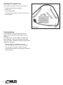
Lighting Kit Components
The complete 1565LLK kit contains the following:
• 2-lamp electrical harness assembly
• 4 cable clips
• 2 grounding washers
• 2 halogen lamps (Type T3-119 mm, 100 W, 130 V)
• Wiring diagram
Kit Content

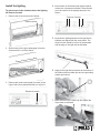
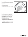
3
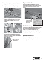
Remove screw
Remove 4 screws
Remove burner from fi rebox
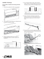
Install the lighting
To gain access to the location where the lighting
kit must be located
1. Remove the screw at right end of burner.
2. Slide burner to the right to disengage it from the
orifi ce and lift it out of the fi rebox.
3. Remove the small access plate (4 screws) to the
right of the burner plate and discard or recycle it.
4. At the bottom of the fi rebox near the back panel,
remove the 4 screws as indicated. These screws
are to be used to fi x the lighting harness to the
fi r e b o x .
5. Lay down the lighting harness so the light fi xture
brackets are aligned with the screw holes. The
electrical cord should be in front of the brackets
and the plug on the right side as indicated.
6. Lightly fi x the light fi xture brackets to the bottom of
the fi rebox with two cable clips and one grounding
washer per bracket.
7. Insert the wire into the cable clip and tighten the
clip screws as indicated.
Remove 4 screws

4
Apply label
Clean the area of sheet metal in front of the lighting
harness, peel the self-adhesive backing from the label
provided with the kit and apply the label to the bottom
of the fi rebox.
Test the lighting
It may be desireable to test the lighting operation
before reassembling the burner and completeing the
fi replace installation.
The electrical wiring from the wall dimmer to the
appliance case should already be done so that when
you plug the lighting kit into the receptacle installed in
the appliance, you can test the lighting with the wall
dimmer.
Reassemble the unit
Reassemble the unit in reverse order and continue
with the heater installation following the installation
instructions supplied with the heater.
Apply label in
front to lighting
harness
Receptacle
in lower
right corner
of liner box
8. Put on some gloves before you install the halogen
light bulbs as the natural oil from skin will shorten
the life of the bulb.
9. Carefully fi t the halogen light bulbs into each bulb
bracket.
10. Thread the electric plug through the access hole
so the plug goes under the fi rebox. Fix the access
plate to the fi rebox bottom with 4 screws as
indicated.
11. Plug the power cord into the receptacle.
Note: Ensure you use the correct receptacle if the
receptacles are controlled separately (they should
be labelled).

5
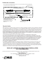
Type T3-118mm, 100W, 130V
Halogen Lamps (2)
Metal access plate with
grommet
screwed to base of firebox
Lamp holders,
screwed to base of firebox (2)
High temp. wire encased in
high temp. sleeve.
3-prong grounded plug
Ground wire
riveted to access plate
Model 1565 LLK Decorative Lighting Kit
120 VAC, 60Hz., less than 2 Amps
Manufactuered by Miles Industries Ltd.
North Vancouver B.C, Canada
4003127/01
NOTE - ALL WIRING IS SPECIFIC TO THIS KIT AND SHOULD ONLY BE REPLACED WITH ORIGINAL EQUIPMENT WIRING
FROM THE MANUFACTURER
Inside of metal firebox
Wiring diagram
PLEASE LEAVE INSTALLATION INSTRUCTIONS
WITH THE HOMEOWNER.
Limited warranty policy
Miles Industries Ltd. warrants all components of the model 1565LLK Lighting Kit for a period of one year from the
date of purchase against defects in materials or workmanship. This warranty covers only the cost of defective
parts and applies only to the original consumer purchaser. The replacement of defective parts by Miles Industries
Ltd. will be without charge during the warranty period. This warranty does not extend to (1) components damaged
by accident, neglect, misuse, abuse, alteration, and negligence of others, including the installation thereof by
unqualifi ed installers (2) the costs of removal, reinstallation or transportation of defective parts or (3) incidental or
consequential damages.
THIS WARRANTY IS EXPRESSLY IN LIEU OF ALL OTHER WARRANTIES, EXPRESSED OR IMPLIED,
INCLUDING THE WARRANTY OF MERCHANTABILITY OF FITNESS FOR PURPOSE AND OF ALL OTHER
OBLIGATIONS OR LIABILITIES. MILES INDUSTRIES LTD. DOES NOT ASSUME, NOR HAS IT AUTHORIZED
ANY PERSON INCLUDING ITS SALES REPRESENTATIVES TO ASSUME FOR IT, ANY OTHER OBLIGATION
OR LIABILITY IN CONNECTION WITH THE SALE OR USE OF THE MODEL 1565LLK LIGHTING KIT.
A qualifi ed installer, in accordance with the instructions supplied must install the model 1565LLK Lighting Kit. The
defective components should be returned at your expense to the dealer from where the product was purchased or
authorized service agent. The sales invoice evidencing proof of purchase and date of purchase must accompany any
components returned for warranty repair/replacement. Miles Industries Ltd. reserves the right to repair and return any
defective component.
Designed and Manufactured by / for
Miles Industries Ltd.
190 – 2255 Dollarton Highway, North Vancouver, B.C., CANADA V7H 3B1
Tel. 604-984-3496 Fax 604-984-0246
www.valorfi replaces.com
Because our policy is one of constant development and improvement, details may vary slightly from those given in this publication.

6
Éclairage d’ambiance 1565LLK
Homologué par la ACN (CSA) pour usage exclusif avec les foyers Valor 1500 et 1700
Note : Ce kit doit être installé et entretenu par un installateur qualifi é, une agence de service
certifi ée ou un fournisseur de gaz. Ces instructions doivent être utilisées conjointement avec les
instructions d’installation des modèles mentionnés ci-haut.
MISE EN GARDE : Si les instructions fournies dans le présent guide ne sont pas suivies à la
lettre, un feu ou une explosion pourraient résulter et causer des dommages matériels, des
blessures ou la mort.
MISE À LA TERRE : La prise de courant utilisée pour brancher cet appareil doit être installée et
mise à la terre conformément aux codes locaux et, en l’absence de codes locaux, elle doit être
conforme à la version courante du Code canadien de l’électricité CSA C22.1 ou, aux États-Unis, à la
version courante du National Electrical Code ANSI/NFPA 70.
Description of système
Les foyers 1500 et 1700 ont été conçus pour permettre
l’installation d’un éclairage d’ambiance. Le 1565LLK
est conçu pour projeter sa lumière vers le haut dans
l’espace entre le panneau arrière et la plateforme hori-
zontale qui entoure le brûleur. L’éclairage met en valeur
le relief des panneaux à cannelures (utilisation décon-
seillée avec les panneaux de verre).
Il est préférable d’installer l’éclairage d’ambiance
au même moment que le foyer quoique cela peut être
fait à une date ultérieure en autant que le câblage élec-
trique soit déjà installé dans la caisse de l’appareil.
Le kit d’éclairage d’ambiance 1565LLK doit être rac-
cordé à une prise de courant située dans la caisse
de l’appareil. Nous conseillons un gradateur mural
marche-arrêt (fourni par l’électricien) pour alimenter
la prise de courant.
Les directives ci-jointes concernent l’installation du kit
d’éclairage d’ambiance seulement. Pour savoir com-
ment et où installer l’alimentation électrique au foyer,
consultez le guide d’installation fourni avec le foyer.
L’entretien futur du kit d’éclairage peut être fait par
l’ouverture de la fenêtre sans qu’il soit nécessaire de
sortir le foyer du mur.
Exigences électriques
Ce kit d’éclairage doit être raccordé à une prise de cou-
rant montée dans la caisse du foyer. L’alimentation de
la prise de courant doit être contrôlée par un gradateur
mural marche-arrêt, lequel n’est pas fourni avec ce kit.
Si vous utilisez une prise de courant double pour
alimenter également le ventilateur de circulation d’air,
vous devrez fractionner les deux prises et ajouter un
fi l conducteur de façon à maintenir un contrôle séparé
pour le ventilateur et l’éclairage (consultez les direc-
tives incluses avec le foyer).
Le ventilateur doit être branché dans une prise de cou-
rant de 120 Volts, 1 phase, 60 Hz. L’intensité de la
charge pleine est de moins de 2 ampères.
NOTE : Le câblage électrique doit être déjà
installé dans la caisse de l’appareil avant
de procéder à l’installation de l’éclairage.
Série L1 et L2
DIRECTIVES D’INSTALLATION ET D’OPÉRATION
LE PREMIER
FOYER À GAZ RADIANT
MC
®

7
Considérations
Nous recommandons fortement l’installation de ce
kit d’éclairage avant d’avoir complété l’installation du
foyer.
Si vous installez ce kit après que le foyer ait été
complètement installé, procédez de la façon suivante
à l’aide des directives indiquées dans le guide du
consommateur fourni avec le foyer :
• Coupez l’alimentation de gaz de l’appareil à la
soupape afi n d’éviter que la télécommande allume
le foyer automatiquement.
• Elevez les portes de chaque côté de la bordure,
la plinthe de la bordure, fenêtre, lit de combustion,
plateforme de vermiculite, supports de plateforme
du milieu (avant et arrière).
Contenu du kit
Le kit d’éclairage d’ambiance 1565LLK comprend les
pièces suivantes :
• Harnais d’éclairage à 2 lampes
• 4 serre-fi ls
• 2 écrous de mise à la terre
• 2 lampes halogènes (Type T3-119 mm, 100 W, 130 V)
• Schéma des connexions
Contenu du kit

8
Enlevez la vis
Enlevez 4 vis
Enlevez le brûleur du foyer
Installez l’éclairage
Pour accéder à l’endroit où l’éclairage doit être
installé
1. Enlevez la vis retenant le brûleur à son support.
2. Tirez le brûleur vers la droite pour le débrancher de
l’injecteur et sortez-le du foyer.
3. Enlevez la plaquette d’accès (4 vis) située à
la droite de la plaque du brûleur et jetez-la ou
recyclez-la.
4. Sur le fond de la boîte de foyer, près de la paroi
arrière, enlevez 4 vis tel qu’indiqué. Ces vis seront
utilisées pour fi xer le harnais d’éclairage au foyer.
5. Placez le harnais en alignant les supports de
lampe aux trous de vis. Le fi l électrique doit être
placé devant les supports et la fi che doit être à
droite.
6. Fixez sans serrer les vis les supports de lampe à
l’aide de deux serre-fi ls et d’un écrou de mise à la
terre pour chaque support.
7. Insérez le fi l dans les serre-fi ls et serrez les vis tel
qu’indiqué.
Enlevez 4 vis

9
Prise de courant en
bas à la droite dans
la caisse du foyer
Apposez l’étiquette
Nettoyez la surface de métal devant le harnais
d’éclairage. Pelez le papier protecteur de l’étiquette
fournie avec le kit et collez l’étiquette à l’endroit
nettoyé.
Vérifi ez l’éclairage
Il peut être souhaitable de revérifi er le fonctionnement
de l’éclairage d’ambiance avant de réassembler le
brûleur et de compléter l’installation du foyer.
Le câblage électrique du gradateur à l’appareil devrait
être déjà installé lorsque vous branchez l’éclairage dans
la caisse du foyer. Vérifi ez la fonction du gradateur.
Réassemblez le foyer
Réassemblez le foyer dans l’ordre inverse duquel vous
avez commencé l’installation et continuez à installer le
foyer tel qu’indiqué dans le guide d’installation fourni
avec le foyer.
Fixez l’étiquette
devant le harnais
d’éclairage
8. Portez des gants pour manipuler les lampes
halogènes car l’huile naturelle de la peau réduit
l’effi cacité de ce type de lampe.
9. Avec précautions, fi xez une lampe halogène sur
chaque support.
10. Faitez passer la fi che dans le trou d’accès pour
qu’elle soit dirigée sous la boîte de foyer. Fixez
la plaquette attachée au fi l à l’aide de 4 vis tel
qu’indiqué.
11. Branchez la fi che dans la prise de courant.
Note : Assurez-vous d’utiliser la bonne prise si
les deux prises contrôlent des kits diff érents (elles
devraient être identifi ées).

10
Conçue et fabriquée par / pour
Miles Industries Ltd.
190 – 2255 Dollarton Highway, North Vancouver, BC, CANADA V7H 3B1
Tél. 604-984-3496 Téléc. 604-984-0246
www.foyervalor.com
Parce que nous favorisons une politique de développement continu, certains détails de la présente publication peuvent varier.
VEUILLEZ LAISSER CES DIRECTIVES D’INSTALLATION
AU CONSOMMATEUR.
Garantie limitée
Miles Industries Ltd. garantie toutes les pièces du L’éclairage d’ambiance 1565LLK contre les défauts de matériaux
ou de main-d’oeuvre pour une période de un (1) an à compter de la date d’achat. Cette garantie ne couvre que le
coût des pièces défectueuses et ne s’applique qu’à l’acheteur original. Le remplacement de pièces défectueuses
par Miles Industries Ltd. s’eff ectuera sans frais durant la période de garantie. Cette garantie ne couvre pas (1) les
pièces endommagées par accident, négligence, usage impropre ou abusif, transformation, et négligence d’autrui,
incluant celle d’installateurs non-qualifi és, (2) les frais d’enlèvement, de réinstallation ou de transport des pièces
défectueuses ou (3) les dommages-intérêts directs ou indirects.
CETTE GARANTIE REMPLACE TOUTES AUTRES GARANTIES, EXPRESSES OU IMPLICITES,
INCLUANT LES GARANTIES DE QUALITÉ MARCHANDE OU D’UTILISATION DE L’APPAREIL À DES FINS
PARTICULIÈRES AINSI QUE TOUTES AUTRES OBLIGATIONS OU RESPONSABILITÉS. MILES INDUSTRIES
LITD. N’ASSUME, NI N’AUTORISE AUCUNE PERSONNE INCLUANT SES REPRÉSENTANTS AUX VENTES
OU DÉTAILLANTS (MARCHANDS) AUTORISÉS D’ÉTENDRE OU D’ASSUMER EN SON NOM, AUCUNE
AUTRE OBLIGATION OU RESPONSABILITÉ EN RELATION À LA VENTE OU L’UTILISATION DU KIT
D’ÉCLAIRAGE D’AMBIANCE 1565LLK.
Un installateur qualifi é doit installer le L’éclairage d’ambiance 1565LLK selon les directives fournies avec le kit.
Toute pièce défectueuse couverte par cette garantie doit être retournée, aux frais de l’acheteur, au détaillant
ou marchand ayant vendu ce kit ou à un agent autorisé. Toute pièce présentée en vertu de cette garantie, pour
réparation ou remplacement, doit être accompagnée du reçu de caisse ou facture à titre de preuve d’achat. Miles
Industries Ltd. se réserve le droit de réparer ou retourner toute pièce défectueuse.
Lampes halogènes (2)
Type T3-118 mm, 100 W, 130 V
Plaquette d’accès en métal avec
passe-câble vissée à la base de
la boîte de foyer
Supports de lampes (2) vissés
à la base de la boîte de foyer
Fil haute température
enveloppé dans une gaine
à haute température
Fiche de mise à la terre
à 2 lames et 1 tige
Fil de mise à la terre riveté
à la plaquette d’accès
Éclairage d’ambiance 1565LLK
120 VAC, 60 Hz, moins de 2 A
Fabriqué par Miles Industries Ltd.
North Vancouver B.C, Canada
4003127-01F
NOTE - LE FILAGE ET LES BORNES SONT SPÉCIFIQUES À CE KIT ET NE DEVRAIENT ÊTRE REMPLACÉS QUE PAR DE
L’ÉQUIPEMENT ORIGINAL DU MANUFACTURIER
Dans la boîte de foyer
en métal
Schéma des connexions
-
 1
1
-
 2
2
-
 3
3
-
 4
4
-
 5
5
-
 6
6
-
 7
7
-
 8
8
-
 9
9
-
 10
10


dans d''autres langues
- English: Valor 1565LLK Owner's manual
Documents connexes
-
Valor 546LF ZC Le manuel du propriétaire
-
-
-
-
-
-
-
-
-