Tripp Lite SMX700HGL & SMX1200XLHGL Le manuel du propriétaire
- Catégorie
- Alimentations sans interruption (UPS)
- Taper
- Le manuel du propriétaire

1
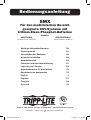
Owner’s Manual
SMX
Medical-Grade UPS Systems
with Lithium Iron Phosphate Batteries
Models:
Important Safety Instructions 2
Package Contents 5
Connecting the Batteries 6
Quick Installation 7
Basic Operation 8
Guidance and Manufacturer’s Declaration 11
Storage & Service 13
Battery Warranty Information 14
Regulatory Compliance 14
Español 15
Français 29
Русский 43
Deutsch 57
SMX700HGL
(Series Number: AG-031B)
SMX1200XLHGL
(Series Number: AG-031C)
1111 W. 35th Street, Chicago, IL 60609 USA • www.tripplite.com/support
Copyright © 2018 Tripp Lite. All rights reserved.
18-10-326-933821.indb 1 11/7/2018 11:17:04 AM

2
Important Safety Instructions
Statement of Intended Use
Tripp Lite Medical-Grade UPS Systems are intended to support and protect non-medical computer
equipment and medical devices that require leakage current reduction, surge protection, voltage
regulation, line noise filtering and battery backup during power outages and generator testing, both
inside and outside patient care areas. Tripp Lite’s Medical-Grade UPS Systems come with hospital-
grade plugs and receptacles that reduce leakage to below 100μA.
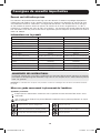
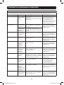
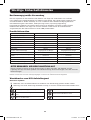
Product Information
SMX700HGL SMX1200XLHGL
AC Input Voltage 230V 230V
Input Amp(s) 3.6 5
Output Amp(s) 2 3.3
Rated Power (VA/Watts) 700VA, 450W 1000VA, 750W
Frequency 50/60 Hz 50/60 Hz
No. of Phases Single Single
Class Type Class I Class I
Plug/Connector Type Inlet C14 with dongle Inlet C14 with dongle
Operation Continuous Continuous
AC Input Protection (Qty/type/rating) Input breaker (2 x 5A) thermal Input breaker (2 x 6A) thermal
Max Leakage Current (uA) Less than 100uA Less than 100uA
Weight 14.3 kg 15.9 kg
Known Contraindication None None
SAVE THESE INSTRUCTIONS
This manual contains important instructions that should be followed during the installation,
operation and storage of all Tripp Lite UPS Systems. Failure to heed these warnings may affect
your warranty.
Note: Your UPS incorporates overcurrent protection in both the L1 and L2 input conductors.
UPS Location Warnings
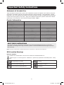
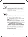
Relevant Symbols
Denotes that information in the manual should be reviewed before use.
Used to signal as a warning that a statement is particularly important and could pose a safety
risk.
Warning-Dangerous Voltage No sitting
Denotes general warning sign No stepping on surface
Refer to Instruction Manual/Booklet No pushing
18-10-326-933821.indb 2 11/7/2018 11:17:05 AM

3
Important Safety Instructions
• Do not use this equipment within oxygen-enriched atmospheres, or within 0.3 m of a point at
which an oxygen-enriched atmosphere is intentionally vented.
• Use caution when lifting UPS. Because of the considerable weight of all UPS systems, at least
two people should assist in lifting and installing them.
• Install your UPS indoors, away from excess moisture or heat, dust or direct sunlight.
• For best performance, the UPS should be used in a location that meets the following conditions:
Temperature: 0 to 40° C; Humidity: 0 to 95% (non-condensing);
Elevation: <2,000 m above sea level; Pressure: >95kPa
• Leave adequate space around all sides of the UPS for proper ventilation. Do not obstruct its vents
or fan openings.
• Do not mount unit with its front or rear panel facing down (at any angle). Mounting in this manner
will seriously inhibit the unit’s internal cooling, eventually causing product damage not covered
under warranty.
• The UPS is not intended for patient contact. Avoid installations that will cause accidental patient
contact.
UPS Connection Warnings
• The UPS contains its own energy source (battery). The output terminals may be live even when
the UPS is not connected to an AC supply.
• Connect your UPS to a properly grounded AC power outlet. Do not modify the UPS’s plug in a
way that would eliminate the UPS’s connection to ground. Do not use adapters that eliminate the
UPS’s connection to ground.
• Do not plug your UPS into itself; this will damage the UPS and void your warranty.
• If you are connecting your UPS to a motor-powered AC generator, the generator must provide
filtered, frequency-regulated output.
• To remove the UPS from the supply mains, the appliance inlet serves as a disconnect device.
• Once connected, do not limit access to the input plug. The plug must be accessible to be used as
a means of disconnection.
• When connecting the UPS to a power outlet, ensure the power outlet is provided with suitable
overcurrent protection in accordance with national and local electrical codes. Ensure the
overcurrent protection has a minimum of 1500A breaking capacity.
CAUTION: Do not remove cover for 5 minutes after disconnecting all sources of
supply. Risk of electric shock—hazardous live parts inside. User must not remove
cover. No user serviceable parts inside. Refer servicing to qualified service
personnel. This UPS receives power from more DC sources; disconnection of the
AC and DC source is required to de-energize the unit before servicing.
CAUTION: To ensure proper grounding with supply mains power, the input cord must
be connected with an approved country-specific plug with a protective earth ground
connection.
CAUTION: If this product is operated on battery (not connected to mains power),
adequate safeguards should be employed to protect against accidental contact
with AC power conductors.
CAUTION: Do not exceed total rated output.
WARNING: No modification of this equipment is allowed.
18-10-326-933821.indb 3 11/7/2018 11:17:05 AM

4
Important Safety Instructions
Equipment Connection Warnings
• Do not use Tripp Lite UPS Systems for life-support applications in which a malfunction or failure
of a Tripp Lite UPS System could cause failure or significantly alter the performance of a life-
support device.
• The AC output cord length should not exceed 33 ft. (10 m).
• Do not connect surge suppressors or extension cords to the output of your UPS. This might
overload the UPS and will void the surge suppressor and UPS warranties.
CAUTION: The unit is for exclusive interconnection with IEC 60601-1 certified
equipment in the patient environment and IEC 60950-1 certified equipment outside
of the patient environment. Do not contact SIP/SOP (such as the USB port, RS232
port, etc.) and the patient at the same time.
Battery Warnings
• Batteries can present a risk of electrical shock and burn from high short-circuit current. Observe
proper precautions. Do not dispose of the batteries in a fire. Do not open the UPS or batteries.
Do not short or bridge the battery terminals with any object. Unplug and turn off the UPS before
performing battery replacement. Use tools with insulated handles. There are no user-serviceable
parts inside the UPS. Only authorized service personnel using the same number and type
of batteries (lithium iron phosphate) should perform battery replacement. The batteries are
recyclable. At the end of the UPS unit’s life, follow best practice by discharging the battery prior to
disposal. Refer to local codes for disposal requirements. Tripp Lite offers a complete line of UPS
System Replacement Battery Cartridges (R.B.C.). Visit Tripp Lite on the Web at
www.tripplite.com/products/battery-finder/ to locate the specific UPS replacement
battery.
• Do not operate UPS without batteries.
CAUTION: The unit is intended for use with lithium iron phosphate batteries
provided by Tripp Lite. DO NOT mix with sealed lead acid batteries. This model does
not support external battery packs. DO NOT attempt to add external batteries.
UPS and Battery Recycling
Please recycle Tripp Lite Products. The batteries used in Tripp Lite products are lithium iron
phosphate batteries. These batteries are highly recyclable. Please refer to local codes for
disposal requirements.
Call Tripp Lite for recycling info at 1.773.869.1234.
For up-to-date information on recycling the batteries in this UPS or any Tripp Lite product,
visit Tripp Lite’s website: http://www.tripplite.com/support/recycling-program/
Replacement Batteries
MODEL
BATTERY
AND QUANTITY
NOMINAL VOLTAGE
OF BATTERY STRING PART NUMBER
SMX700HGL Lithium Iron Phosphate
12V / 3 pcs.
39.6V, 5Ah RBC51L / 3 pcs.
SMX1200XLHGL Lithium Iron Phosphate
12V / 3 pcs.
39.6V, 5Ah RBC51L / 3 pcs.
18-10-326-933821.indb 4 11/7/2018 11:17:05 AM

5
Important Safety Instructions
Package Contents
Maintenance:
• Other than battery replacement, the UPS does not require maintenance. There are no user-
serviceable parts inside. Battery replacement should only be performed by qualified service
personnel.
Cleaning/Disinfecting:
• Before cleaning or disinfecting, the UPS should be turned off and unplugged.
• For cleaning the UPS, only a damp cloth should be used.
• For disinfecting the UPS, a damp cloth wetted with isopropyl alcohol may be used. No other
cleaning agent should be used.
UPS and Battery Disposal
• Always comply with local ordinances for proper methods of recycling and disposal of electronic
equipment.
• Batteries can present risk of electric shock, burn and fire if not disposed of properly.
SMX700HGL
• 1.8 m USB Cable
• 1.8 m DB9 Cable
• Owner’s Manual
SMX1200XLHGL
• 1.8 m USB Cable
• 1.8 m DB9 Cable
• Owner’s Manual
18-10-326-933821.indb 5 11/7/2018 11:17:05 AM

6
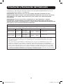
Connecting the Batteries
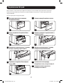
1
Remove the two screws on
the battery door.
2
Remove the battery door.
1
2
3
4
5 6
7
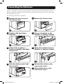
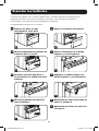
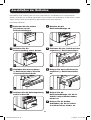
The UPS is shipped with the battery disconnected. The battery must be connected for the UPS to
operate. Connect the batteries to the UPS prior to connecting the UPS to AC mains or connecting
any equipment to the UPS.
The installation procedure is as follows:
3
Slightly slide the battery
pack out.
4
Remove insulation on the
negative (-) battery terminal.
5
Connect the negative (-)
battery terminal to the black
battery wire.
6
Apply the insulation tape to
negative (-) battery terminal.
7
Slide the battery pack back
into the UPS.
8
Reinstall the battery door
removed in step 2.
9
Reinstall the two screws
removed in step 1.
18-10-326-933821.indb 6 11/7/2018 11:17:08 AM

7
Quick Installation
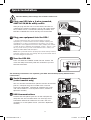
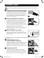
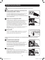
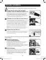
1
Plug your UPS into a 3-wire grounded,
230V AC 50/60 Hz utility outlet.
After you plug the UPS into a live AC outlet, the UPS will
automatically charge its batteries, but will not supply power
to its outlets until it is turned ON (see Step 3 below). The
BATTERY CHARGE LED will be the only LED illuminated.
2
Plug your equipment into the UPS.*
* You will overload the UPS if the total VA ratings for all the
equipment you connect exceeds the UPS’s Output Capacity (see
Specifications). To find your equipment’s VA ratings, look on their
nameplates. If the equipment is listed in amps, multiply the number
of amps by 230 to determine VA. (Example: 1 amp × 230 V = 230
VA). If you are unsure you have overloaded the UPS’s outlets, see
“OUTPUT LOAD LEVEL” LED description.
Note: UPS system will function properly upon initial startup; however,
maximum runtime for the unit’s battery will only be accessible after it
has been charged for 24 hours.
3
Turn the UPS ON.
Press and hold the “POWER” button for one second. The
alarm will beep once briefly after one second has passed.
Release the button.
NORM DELAY
1
2
3
NORM DELAY
NORM DELAY
1
2
The following connections are optional; your UPS will function properly without these
connections:
1
Serial Communications
(select models only)
You can connect the DB9 serial port on the UPS to the DB9
port of a computer with the included cable. Use with
Tripp Lite’s PowerAlert
®
software for automatic file saves
and safe shutdown in case of power failure. (See Basic
Operation Section.)
2
USB Communications
Connect the USB port of your UPS to the USB port of a
computer with the included cable. Use with Tripp Lite’s
PowerAlert software for automatic file saves and safe
shutdown in case of power failure. (See Basic Operation
Section.)
The UPS battery must charge for 24 hours before use.
18-10-326-933821.indb 7 11/7/2018 11:17:09 AM

8
Basic Operation
Buttons
“POWER” Button:
• To turn the UPS ON: With the UPS plugged into a live AC wall outlet,* press
and hold the POWER button for one second.** Release the button. If utility
power is absent, you can “cold-start” the UPS (i.e., turn it ON and supply
power for a limited time from its batteries***) by pressing and holding the
POWER button for about two seconds.**
• To turn the UPS OFF: With the UPS ON and receiving utility power, press and
hold the POWER button for one second.** Then unplug the UPS from the wall
outlet. The UPS will be completely OFF.
* After you plug the UPS into a live AC outlet, the UPS will automatically charge its batteries,
but will not supply power to its outlets until it is turned ON. ** The alarm will beep once
briefly after the indicated interval has passed. *** Fully charged batteries are recommended.
“MUTE/TEST” Button:
To Silence (or “Mute”) UPS Alarms: Briefly press and release the MUTE/TEST
button.*
To Run a Self-Test: With your UPS plugged in and turned ON, press and hold
the MUTE/TEST button for two seconds.* The alarm will beep once. Release the
button, and the UPS will perform a self-test. See “Results of a Self-Test” below.
Note: you can leave connected equipment on during a self-test. Your UPS, however, will not
perform a self-test if it is not turned ON (see “POWER” Button description).
CAUTION! Do not unplug your UPS to test its batteries. This will
remove safe electrical grounding and may introduce a damaging
surge into your network connections.
Results of a Self-Test: The test will last approximately 10 seconds as the UPS
switches to battery to test its load capacity and battery charge.** If the “OUTPUT
LOAD LEVEL” LED remains lit red and the alarm continues to sound after the test,
the UPS’s outlets are overloaded. To clear the overload, unplug some of your
equipment and run the self-test repeatedly until the “OUTPUT LOAD LEVEL” LED is
no longer lit red and the alarm is no longer sounding.
CAUTION! Any overload that is not corrected by the user
immediately following a self-test may cause the UPS to shut down
and cease supplying output power in the event of a blackout or
severe brownout.
If the “BATTERY WARNING” LED remains lit and the alarm continues to sound
after the test, the UPS batteries need to be recharged or replaced. Allow the
UPS to recharge continuously for 12 hours, and repeat the self-test. If the
LED remains lit, contact Tripp Lite for service. If your UPS requires battery
replacement, visit www.tripplite.com/products/battery-finder to locate the specific
Tripp Lite replacement battery for your UPS.
* The alarm will beep once briefly after the indicated interval has passed. ** The “POWER”
LED will be flashing and the “OUTPUT LOAD LEVEL” and “BATTERY CHARGE” LEDs will be lit
and the UPS alarm will sound.
18-10-326-933821.indb 8 11/7/2018 11:17:09 AM

9
Basic Operation
Indicator Lights
All Indicator Light descriptions apply when the UPS is plugged into an AC outlet and turned on.
“POWER” LED: This green LED lights continuously when the UPS is ON and
supplying connected equipment with AC power from a utility source. The LED
flashes and an alarm sounds (4 short beeps followed by a pause) to indicate the
UPS is operating from its internal batteries during a blackout or severe brownout.
If the blackout or severe brownout is prolonged, you should save files and shut
down your equipment since internal battery power will eventually be depleted.
See “BATTERY CHARGE” LED description below.
“VOLTAGE CORRECTION” LED: This green LED lights continuously whenever the
UPS is automatically correcting high or low AC voltage on the utility line without
the assistance of battery power. The UPS will also emit a slight clicking noise.
These are normal, automatic operations of the UPS. No action is required on your
part.
“OUTPUT LOAD LEVEL” LED: This multicolored LED indicates the approximate
electrical load of equipment connected to the UPS’s AC outlets. It will turn from
green (light load) to yellow (medium load) to red (overload). If the LED is red
(either illuminated continuously or flashing), clear the overload immediately by
unplugging some of your equipment from the outlets until the LED changes from
red to yellow (or green) and the alarm is no longer sounding.
CAUTION! Any overload that is not corrected by the user
immediately may cause the UPS to shut down and cease
supplying output power in the event of a blackout or severe
brownout.
“BATTERY CHARGE / BATTERY POWER” LED: When the UPS is operating from
utility power, this multicolored LED indicates the approximate charge state of
the UPS’s internal batteries: red indicates the batteries are beginning to charge,
yellow indicates the batteries are roughly midway through charging and green
indicates the batteries are fully charged. When the UPS is operating from battery
power during a blackout or severe brownout, this LED indicates the approximate
amount of energy (ultimately affecting runtime) that the UPS’s batteries will
provide: red indicates a low level of energy, yellow indicates a medium level of
energy and green indicates a high level of energy.
Because runtime performance of all UPS batteries will gradually deplete over
time, it is recommended you periodically perform a self-test (see “MUTE/TEST”
Button description) to determine the energy level of your UPS batteries BEFORE
a blackout or severe brownout occurs. During a prolonged blackout or severe
brownout, you should save files and shut down your equipment because battery
power will eventually be depleted. When the LED turns red and an alarm sounds
continuously, it indicates the UPS’s batteries are nearly out of power and UPS
shutdown is imminent.
“BATTERY WARNING” LED: This LED lights red and an alarm sounds
intermittently after you initiate a self-test (See “MUTE/TEST” Button description)
to indicate the UPS batteries need to be recharged or replaced. Allow the UPS to
recharge continuously for 12 hours, and repeat the self-test. If the LED continues
to light, contact Tripp Lite for service. If your UPS requires battery replacement,
visit www.tripplite.com/products/battery-finder to locate the specific Tripp Lite
replacement battery for your UPS.
18-10-326-933821.indb 9 11/7/2018 11:17:10 AM

10
Basic Operation
Other UPS Features
AC Receptacles: The receptacles provide your connected equipment with AC
line power during normal operation and battery power during blackouts and
brownouts. They also protect your equipment against damaging surges and line
noise.
USB or DB9 Communication Port: These ports can connect your UPS to any
computer for automatic file saves and unattended shutdown in the event of a
power failure. Use with Tripp Lite’s PowerAlert Software and appropriate USB or
DB9 cable. You can obtain the software FREE via the Web at www.tripplite.com.
Any user-supplied DB9 pass-through or USB cable may be used to connect your
UPS to your computer.
Note: This connection is optional. The UPS will work properly without this connection.
Battery Replacement Door: Under normal conditions, the original battery in
your UPS will last several years. Battery replacement should be performed only
by qualified service personnel. Refer to “Battery Warnings” in the Safety section.
Should your UPS require battery replacement, visit www.tripplite.com/products/
battery-finder to locate the specific replacement battery for your UPS.
Input Breakers: Protects your electrical circuit from overcurrent draw from the
UPS load. If breaker trips, remove some of the load, then reset it by pressing the
breaker in.
Equipotential Connection: Use this to connect any equipment that requires a
chassis ground.
Power Sensitivity Adjustment: This dial is normally set fully counterclockwise,
which enables the UPS to protect against waveform distortions in its AC input.
When such distortion occurs, the UPS will normally switch to providing PWM
sine wave power from its battery reserves for as long as the distortion is present.
In areas with poor utility power or where the UPS’s input power comes from a
backup generator, chronic waveform distortion could cause the UPS to switch
to battery too frequently, draining its battery reserves. You may be able to
reduce how often your UPS switches to battery due to waveform distortion by
experimenting with different settings for this dial. As the dial is turned clockwise,
the UPS becomes more tolerant of variations in its input power’s AC waveform.
Note: The further the dial is adjusted clockwise, the greater the degree of waveform
distortion the UPS will allow to pass to connected equipment. When experimenting with
different settings for this dial, operate connected equipment in a safe test mode so that the
effect on the equipment of any waveform distortions in the UPS’s output can be evaluated
without disrupting critical operations.
NORM DELAY
18-10-326-933821.indb 10 11/7/2018 11:17:11 AM

11
Guidance and Manufacturer’s Declaration
This equipment is suitable for hospitals except for near active HF SURGICAL EQUIPMENT and the RF
shielded room of an ME SYSTEM.
WARNING: Use of this equipment adjacent to or stacked with other equipment should
be avoided because it could result in improper operation. If such use is necessary, this
equipment and the other equipment should be observed to verify that they are operating
normally.
WARNING: Use of accessories, transducers and cables other than those specified or
provided by the manufacturer of this equipment could result in increased electromagnetic
emissions or decreased electromagnetic immunity of this equipment and result in improper
operation.
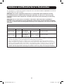
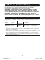
Guidance and Manufacturer’s Declaration—Electromagnetic Emissions
This Medical-Grade UPS is intended for use in the electromagnetic environment specified below. The customer
or the user of this Medical-Grade UPS should assure that it is used in such an environment.
Standard Description Test Level/Limit Guidance
EN 55011:
2009+A1:2010
Radiated
Emissions
Models:
SMX700HGL,
SMX1200XLHGL
Class A Group 1,
30 - 1000 MHz
See notes 1 and 2
EN 55011:
2009+A1:2010
Conducted
Emissions
Models:
SMX700HGL,
SMX1200XLHGL
Class A Group 1,
150 kHz – 30 MHz
See notes 1 and 2
Notes:
1. Group 1: The Medical-Grade UPS uses RF energy only for its internal function. Therefore, its RF emissions are
very low and unlikely to cause any interference in nearby electronic equipment.
2. Class A: The Medical-Grade UPS is suitable for use in all establishments other than domestic and those
directly connected to the public low-voltage power supply network that supplies buildings used for domestic
purposes. NOTE The EMISSIONS characteristics of this equipment make it suitable for use in industrial areas
and hospitals (CISPR 11 class A). If it is used in a residential environment (for which CISPR 11 class B is
normally required) this equipment might not offer adequate protection to radio-frequency communication
services. The user might need to take mitigation measures, such as relocating or re-orienting the equipment.
18-10-326-933821.indb 11 11/7/2018 11:17:11 AM

12
Guidance and Manufacturer’s Declaration
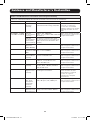
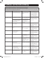
Guidance and Manufacturer’s Declaration—Electromagnetic Immunity
This Medical-Grade UPS is intended for use in the electromagnetic environment specified below. The customer
or the user of this Medical-Grade UPS should assure that it is used in such an environment.
Standard Description Test Level/Limit Guidance
EN 61000-4-2:2009 Electrostatic
Discharge
Immunity
±15 kV Air Discharge
±8 kV Contact Discharge, VCP, HCP
Floors should be wood,
concrete or ceramic tile.
If colors are covered with
synthetic material, the relative
humidity should be at least
30%.
EN 61000-4-3: 2006
+A1:2008+A2:2010
Radiated
Electromagnetic
Immunity
10V/m, 80 - 1000 Mhz
3V/m, 1 to 2.7 GHz at 80% 1kHz AM
Modulation
Mains power quality should be
that of a typical commercial or
hospital environment.
Radiated
Electromagnetic
and Proximity
Fields Immunity
RF wireless communication fields
on Spot Frequencies from Table 9 at
50%, Square wave Modulation 9 to
28 V/m,
EN 61000-3-2:2014 Power
Harmonics
230V, 50/60Hz
Class A Mains power quality should be
that of a typical commercial or
hospital environment.
EN 61000-3-3:2013 Voltage
Fluctuation 230V,
50Hz
Pst ≤ 1, dc ≤ 3.3%, dmax ≤ 6%,
d(t) ≤ 3.3% for 500ms
Mains power quality should be
that of a typical commercial or
hospital environment.
EN 61000-4-4:2012 Electrical Fast
Transient/Burst
Immunity
±2kV on AC Mains
±1 kV on SIP/SOP Ports
Mains power quality should be
that of a typical commercial or
hospital environment.
EN 61000-4-5:2006 Surge Immunity ±0.5 kV, ±1 kV, ±2kV CM Line-Gnd
±0.5 kV, ±1 kV, DM Line-Line
NA on SIP/SOP Ports
Mains power quality should be
that of a typical commercial or
hospital environment.
EN 61000-4-6:2013 Conducted
Immunity
6V rms, on ISM and Amateur bands,
3V rms, 0.15 - 80 MHz, AC Mains
and SIP/SOP Ports
Mains power quality should be
that of a typical commercial or
hospital environment.
EN 61000-4-8:2010 Power Frequency
Magnetic Field
Immunity
30A/m @ 50 Hz or 60 Hz
3 orthogonal orientations
Power frequency magnetic
fields should be at levels
characteristic of a typical
location in a typical
commercial or hospital
environment.
EN 61000-4-11:2004 Voltage
Dips, Short
Interruptions
and Voltage
Variations
Immunity
0%, 0.5 Cycles, 0%, 1 Cycle
70%, 30 Cycles, 0%, 300 Cycles
Mains power quality should be
that of a typical commercial or
hospital environment.
EN 61000-2-2:2004 Power Line
Harmonics and
Inter-Harmonics
Single sinusoidal source of 10V rms,
slowly varied from 140 to 360 Hz.
Mains power quality should be
that of a typical commercial or
hospital environment.
18-10-326-933821.indb 12 11/7/2018 11:17:11 AM

13
Storage & Service
Storage
Before storing your UPS, turn it completely OFF. With the UPS ON and receiving utility power, press
and hold the POWER button for one second (an alarm will beep once briefly after the interval has
passed). Then, unplug the UPS from the wall outlet.
CAUTION! Your UPS has an internal power source. Its outlets may still deliver
current, even after the UPS is unplugged, until the UPS is completely turned OFF
(deactivated).
If you store your UPS for an extended period of time, recharge the UPS batteries once every three
months: plug the UPS into a wall outlet; allow it to charge for 12 hours, and then unplug it and
place it back in storage.
Note: after you plug the UPS in, it will automatically begin charging its batteries; however, it will not supply power
to its outlets (see Quick Installation section). If you leave your UPS batteries discharged for an extended period of
time, they will suffer a permanent loss of capacity.
Permissible Storage and Transportation Conditions
Humidity 0-95% Non-Condensing
Temperature -15°C to 45°C
Elevation 0 to 15,240 m
Atmospheric Pressure >95 kPa
Service
A variety of Extended Warranty and On-Site Service Programs are available from Tripp Lite. For more
information on service, visit www.tripplite.com/support. Before returning your product for service,
follow these steps:
1. Review the installation and operation procedures in this manual to insure that the service
problem does not originate from a misreading of the instructions.
2. If the problem continues, do not contact or return the product to the dealer. Instead, visit
www.tripplite.com/support.
3. If the problem requires service, visit www.tripplite.com/support and click the Product Returns link.
From here you can request a Returned Material Authorization (RMA) number, which is required
for service. This simple on-line form will ask for your unit’s model and serial numbers, along with
other general purchaser information. The RMA number, along with shipping instructions will be
emailed to you. Any damages (direct, indirect, special or consequential) to the product incurred
during shipment to Tripp Lite or an authorized Tripp Lite service center are not covered under
warranty. Products shipped to Tripp Lite or an authorized Tripp Lite service center must have
transportation charges prepaid. Mark the RMA number on the outside of the package. If the
product is within its warranty period, enclose a copy of your sales receipt. Return the product for
service using an insured carrier to the address given to you when you request the RMA.
18-10-326-933821.indb 13 11/7/2018 11:17:11 AM

14
Battery Warranty Information
Regulatory Compliance
Regulatory Compliance Identification Numbers
For the purpose of regulatory compliance certifications and identification, your Tripp Lite product has been
assigned a unique series number. The series number can be found on the product nameplate label, along with
all required approval markings and information. When requesting compliance information for this product, always
refer to the series number. The series number should not be confused with the marking name or model number of
the product.
WEEE Compliance Information for Tripp Lite Customers and Recyclers
(European Union)
Under the Waste Electrical and Electronic Equipment (WEEE) Directive and implementing regulations,
when customers buy new electrical and electronic equipment from Tripp Lite they are entitled to:
• Send old equipment for recycling on a one-for-one, like-for-like basis
(this varies depending on the country)
• Send the new equipment back for recycling when this ultimately becomes waste
UPS and Battery Recycling
Please recycle Tripp Lite Products. The batteries used in Tripp Lite products are lithium iron phosphate
batteries. These batteries are highly recyclable. Please refer to your local codes for disposal
requirements.
Tripp Lite has a policy of continuous improvement. Product specifications are subject to change without notice.
1111 W. 35th Street, Chicago, IL 60609 USA • www.tripplite.com/support
Tripp Lite’s warranty for lithium iron phosphate batteries, including those in the SMX700HGL and
SMX1200XLHGL, is 5 years. These batteries support frequent charge/discharge cycles, such as
mobile cart applications where the UPS is often disconnected from an AC power source or when
the AC power source has frequent outages. Unlike traditional sealed lead acid batteries, lithium
iron phosphate batteries have the ability to cycle multiple times per day and provide up to 10,000
cycles, 20-30 times the cycle life of traditional batteries.
This warranty does not apply to traditional sealed lead acid batteries. Visit www.tripplite.com for
more information and specifics on battery type, battery life and warranty for the UPS you intend to
use for your application.
18-10-326-933821.indb 14 11/7/2018 11:17:11 AM

15
Manual del Propietario
SMX
Sistemas UPS de Grado Médico
con Baterías de Litio-Ferrofosfato
Modelos:
Instrucciones de Seguridad Importantes 16
Contenido del Empaque 19
Conexión de las Baterías 21
Instalación Rápida 21
Operación Básica 22
Orientación y Declaración del Fabricante 25
Almacenamiento y Servicio 27
Información de la Garantía de la Batería 28
Cumplimiento de las Regulaciones 28
English 1
Français 29
Русский 43
Deutsch 57
SMX700HGL
(Número de Serie: AG-031B)
SMX1200XLHGL
(Número de Serie: AG-031C)
1111 W. 35th Street, Chicago, IL 60609 EE. UU. • www.tripplite.com/support
Copyright © 2018 Tripp Lite. Todos los derechos reservados.
18-10-326-933821.indb 15 11/7/2018 11:17:11 AM

16
Instrucciones de Seguridad Importantes
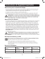
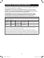
Declaración de Uso Previsto
Los Sistemas UPS de Grado Médico de Tripp Lite están diseñados para soportar y proteger equipo
de computación no médico y dispositivos médicos que requieran reducción de fuga de corriente,
protección contra sobretensiones, regulación de voltaje, filtrado de ruido en la línea y respaldo por
batería durante interrupciones en el servicio eléctrico y prueba del generador, ambos dentro y fuera
de áreas de atención al cuidado de pacientes. Los Sistemas UPS de Grado Médico de Tripp Lite
vienen con clavijas y tomacorrientes de grado hospital que reducen la fuga a menos de 100 µA.
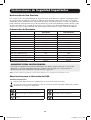
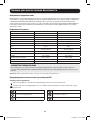
Información del Producto
SMX700HGL SMX1200XLHGL
Voltaje de Entrada de CA 230V 230V
Amperes de Entrada 3.6 5
Amperes de Salida 2 3.3
Potencia Especificada (VA / Watts) 700VA, 450W 1000VA, 750W
Frecuencia 50Hz / 60Hz 50Hz / 60Hz
Nº de Fases Mono Mono
Tipo de Clase Clase I Clase I
Tipo de Clavija/Conector Entrada C14 con llave electrónica Entrada C14 con llave electrónica
Operación Continua Continua
Protección de Entrada de CA (Canti-
dad / Tipo / Especificación)
Breaker térmico de entrada (2
x 5A)
breaker térmico de entrada (2
x 6A)
Corriente Máx de Fuga (µA) Menos de 100 µA Menos de 100 µA
Peso 14.3 kg 15.9 kg
Contraindicación Conocida Ninguna Ninguna
CONSERVE ESTAS INSTRUCCIONES
Este manual contiene instrucciones importantes que deben seguirse durante la instalación,
operación y almacenamiento de todos los Sistemas UPS de Tripp Lite. La omisión en la
observancia de estas advertencias puede afectar la garantía.
Nota: Su UPS incorpora protección contra sobrecorriente en los conductores de entrada L1 y L2.
Advertencias para la Ubicación del UPS
Símbolos Importantes
Significa que debe revisarse la información en el manual antes de usarlo.
Se usa para indicar como advertencia que un párrafo es particularmente importante y puede
representar un riesgo a la seguridad.
Advertencia-Voltaje Peligroso No sentarse
Denota un signo de advertencia general No pararse sobre la superficie
Consulte el Manual / Folleto de Instruc-
ciones
No Empujar
18-10-326-933821.indb 16 11/7/2018 11:17:11 AM

17
Instrucciones de Seguridad Importantes
• No use este equipo en atmósferas enriquecidas con oxígeno o a distancias inferiores a 30.5 cm [1 pie]
de un punto en que se ventile deliberadamente una atmósfera enriquecida con oxígeno.
• Tenga cuidado al levantar el UPS. Debido al considerable peso de todos los sistemas UPS, al menos
dos personas deben ayudar para levantarlos e instalarlos.
• Instale su UPS en interiores, alejado de humedad o calor excesivos, polvo o luz solar directa.
• Para mejor desempeño, el UPS debe usarse en una ubicación que cumpla con las siguientes
condiciones: Temperatura: 0 ºC a 40 °C [32 ºF a 104 ºF]; Humedad: 0% a 95% (sin condensación);
Elevación: <2,000 m sobre el nivel del mar; Presión: >95 kPa
• Deje un espacio adecuado alrededor de todos los lados del UPS para una ventilación apropiada. No
obstruya las ventilaciones o aberturas de los ventiladores.
• No instale la unidad con su panel frontal o posterior viendo hacia abajo (en cualquier ángulo). Al
instalarlo de esta manera inhibirá seriamente el enfriamiento interno de la unidad, causando un daño al
producto que no está cubierto por la garantía.
• El UPS no está previsto para contacto con el paciente. Evite instalaciones que pudieran causar contacto
accidental con el paciente.
Advertencias para la Conexión del UPS
• El UPS contiene su propia fuente de energía (batería). Las terminales de salida pueden estar
energizadas, aún cuando el UPS no esté conectado a una alimentación de CA.
• Conecte su UPS a un tomacorrientes de CA conectado correctamente a tierra. No modifique la clavija
del UPS en modo alguno que pueda eliminar la conexión a tierra del UPS. No use adaptadores que
eliminen la conexión a tierra del UPS.
• No enchufe su UPS en sí mismo; esto dañará al UPS y anulará su garantía.
• Si está conectando su UPS a un generador de CA activado por motor, el generador de proporcionar una
salida filtrada y con frecuencia regulada.
• Para retirar el UPS de la alimentación de la red del servicio público, la clavija del dispositivo sirve como
dispositivo de desconexión.
• Una vez conectado, no limite el acceso a la clavija de entrada. La clavija debe ser accesible para usarla
como medio de desconexión.
• Al conectar el UPS a un tomacorrientes de alimentación, asegúrese que el tomacorrientes de
alimentación cuente con protección adecuada contra sobrecorriente de acuerdo con los códigos
eléctricos nacionales y locales. Asegúrese de que la protección contra sobrecorriente tenga una
capacidad de interrupción mínima de 1500A.
PRECAUCIÓN: No retire la cubierta durante 5 minutos después de desconectar todas
las fuentes de alimentación. Riesgo de electrocución—partes energizadas peligrosas en
el interior. El usuario no debe retirar la cubierta. No hay en el interior partes a las que
el usuario pueda dar servicio. Remita el servicio a personal de servicio calificado. Este
UPS recibe energía de más fuentes de CD; se requiere la desconexión de la fuente de
CA y CD para desenergizar la unidad antes de darle servicio.
PRECAUCIÓN: Para garantizar la correcta conexión a tierra con la alimentación
de energía de la red pública, el cable de entrada debe conectarse con una clavija
específica autorizada para el país con una conexión de protección a tierra.
PRECAUCIÓN: Si este producto está operado en respaldo por batería (no está conectado
a la energía de la red pública), deben emplearse las protecciones adecuadas para
protegerse contra un contacto accidental con conductores de energía de CA.
PRECAUCIÓN: No exceda la salida total especificada.
ADVERTENCIA: No se permite ninguna modificación de este equipo.
18-10-326-933821.indb 17 11/7/2018 11:17:11 AM

18
Instrucciones de Seguridad Importantes
Advertencias para la Conexión del Equipo
• No use los Sistemas UPS de Tripp Lite para aplicaciones de soporte de vida en los que un mal
funcionamiento o falla de un de Sistema UPS de Tripp Lite pudiera causar una falla o alterar
significativamente el desempeño de un dispositivo de soporte de vida.
• La longitud del cable de salida de CA no debe exceder 10 m.
• No conecte supresores de sobretensiones o cables de extensión a la salida de su UPS. Esto
puede sobrecargar al UPS y anulará las garantías del supresor de sobretensiones y del UPS.
PRECAUCIÓN: La unidad es para interconexión exclusiva con equipo certificado por
IEC 60601-1 en el entorno del paciente y equipo certificado por IEC 60950-1 fuera
del entorno del paciente. No haga contacto con SIP / SOP (como el puerto USB,
puerto RS232, etc.) y el paciente al mismo tiempo.
Advertencias de la Batería
• Las baterías pueden presentar un riesgo de descarga eléctrica y quemaduras por la alta corriente
de corto circuito. Observe las precauciones apropiadas. No deseche las baterías en el fuego.
No abra el UPS o las baterías. No ponga en corto o puentee las terminales de la batería con
objeto alguno. Desenchufe y apague el UPS antes de reemplazar la batería. Use herramientas
con mangos aislados. No hay partes dentro del UPS a las que el usuario pueda dar servicio. El
reemplazo de la batería debe realizarlo solo el personal de servicio autorizado usando el mismo
número y tipo de baterías (Litio-Ferrofosfato). Las baterías son reciclables. Al final de la vida
de la unidad del UPS, siga las siguientes buenas prácticas para descargar la batería antes de
desecharla. Para los requisitos de desecho, consulte los reglamentos y códigos locales. Tripp
Lite ofrece una línea completa de Cartuchos de Batería de Repuesto (R.B.C.) para Sistema UPS.
Para localizar la batería de repuesto específica para el UPS, visite Tripp Lite en el sitio
www.tripplite.com.
• No opere el UPS sin baterías.
PRECAUCIÓN: La unidad está diseñada para uso con baterías de Litio-Ferrofosfato
suministradas por Tripp Lite. NO mezcle con baterías selladas de plomo ácido.
Este modelo no soporta módulos de baterías externas. No intente agregar baterías
externas.
Reciclado de la Batería y el UPS
Recicle por Favor los Productos de Tripp Lite. Las baterías usadas en productos de Tripp
Lite son baterías de Litio-Ferrofosfato. Estas baterías son altamente reciclables. Para los
requisitos de desecho, por favor consulte sus códigos locales.
Llame a Tripp Lite al 1.773.869.1234 para obtener información de reciclado.
Para obtener información actualizada sobre el reciclaje de las baterías o cualquier
producto de Tripp Lite, vaya al sitio Web de Tripp Lite: http://www.tripplite.com/support/
recycling-program/
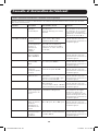
Baterías de Reemplazo
MODELO
BATERÍA
Y CANTIDAD
VOLTAJE NOMINAL
DE LA CADENA DE
BATERÍAS NÚMERO DE PARTE
SMX700HGL Litio-Ferrofosfato de
12V / 3 piezas.
39.6V, 5Ah RBC51L / 3 piezas.
SMX1200XLHGL Litio-Ferrofosfato de
12V / 3 piezas.
39.6V, 5Ah RBC51L / 3 piezas.
18-10-326-933821.indb 18 11/7/2018 11:17:11 AM

19
Instrucciones de Seguridad Importantes
Contenido del Empaque
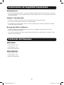
Mantenimiento:
• Fuera del remplazo de baterías, el UPS no requiere mantenimiento. No tiene partes a las que el
usuario pueda dar servicio. El reemplazo de la batería debe llevarse a cabo sólo por personal de
servicio calificado.
Limpieza / Desinfección:
• Antes de la limpieza o desinfección, el UPS debe apagarse y desconectarse.
• Para limpiar el UPS debe usarse solo un trapo húmedo.
• Para desinfectar el UPS puede usarse un trapo humedecido con alcohol isopropílico. No debe
usarse otro agente limpiador.
Desecho del UPS y la Batería
• Cumpla siempre con los reglamentos locales para los métodos adecuados de reciclado y
desecho de equipo electrónico.
• Las baterías pueden presentar el riesgo de descarga eléctrica, quemaduras e incendio si no se
desechan correctamente.
SMX700HGL
• Cable USB de 1.8 m
• Cable DB9 de 1.8 m
• Manual del Propietario
SMX1200XLHGL
• Cable USB de 1.8 m
• Cable DB9 de 1.8 m
• Manual del Propietario
18-10-326-933821.indb 19 11/7/2018 11:17:11 AM

20
Conexión de las Baterías
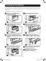
1
Retire los dos tornillos en la
puerta de la batería.
2
Retire la puerta de la batería.
1
2
3
4
5 6
7
El UPS se embarca con la batería desconectada. Para operar el UPS, debe conectarse la batería.
Conecte las baterías al UPS antes de conectar el UPS a la alimentación de CA o conectar cualquier
equipo al UPS.
El procedimiento de instalación es como sigue:
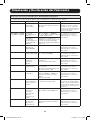
3
Deslice un poco hacia afuera el
módulo de baterías.
4
Quite el aislamiento en la
terminal negativa (-) de la batería.
5
Conecte la terminal negativa (-)
de la batería al cable negro de la
batería.
6
Aplique la cinta de aislar a la
terminal negativa (-) de la batería.
7
Deslice el módulo de baterías
nuevamente dentro del UPS.
8
Reinstale la puerta de la batería
retirada en el paso 2.
9
Reinstale los dos tornillos
retirados en el paso 1.
18-10-326-933821.indb 20 11/7/2018 11:17:15 AM
La page est en cours de chargement...
La page est en cours de chargement...
La page est en cours de chargement...
La page est en cours de chargement...
La page est en cours de chargement...
La page est en cours de chargement...
La page est en cours de chargement...
La page est en cours de chargement...
La page est en cours de chargement...
La page est en cours de chargement...
La page est en cours de chargement...
La page est en cours de chargement...
La page est en cours de chargement...
La page est en cours de chargement...
La page est en cours de chargement...
La page est en cours de chargement...
La page est en cours de chargement...
La page est en cours de chargement...
La page est en cours de chargement...
La page est en cours de chargement...
La page est en cours de chargement...
La page est en cours de chargement...
La page est en cours de chargement...
La page est en cours de chargement...
La page est en cours de chargement...
La page est en cours de chargement...
La page est en cours de chargement...
La page est en cours de chargement...
La page est en cours de chargement...
La page est en cours de chargement...
La page est en cours de chargement...
La page est en cours de chargement...
La page est en cours de chargement...
La page est en cours de chargement...
La page est en cours de chargement...
La page est en cours de chargement...
La page est en cours de chargement...
La page est en cours de chargement...
La page est en cours de chargement...
La page est en cours de chargement...
La page est en cours de chargement...
La page est en cours de chargement...
La page est en cours de chargement...
La page est en cours de chargement...
La page est en cours de chargement...
La page est en cours de chargement...
La page est en cours de chargement...
La page est en cours de chargement...
La page est en cours de chargement...
La page est en cours de chargement...
La page est en cours de chargement...
La page est en cours de chargement...
-
 1
1
-
 2
2
-
 3
3
-
 4
4
-
 5
5
-
 6
6
-
 7
7
-
 8
8
-
 9
9
-
 10
10
-
 11
11
-
 12
12
-
 13
13
-
 14
14
-
 15
15
-
 16
16
-
 17
17
-
 18
18
-
 19
19
-
 20
20
-
 21
21
-
 22
22
-
 23
23
-
 24
24
-
 25
25
-
 26
26
-
 27
27
-
 28
28
-
 29
29
-
 30
30
-
 31
31
-
 32
32
-
 33
33
-
 34
34
-
 35
35
-
 36
36
-
 37
37
-
 38
38
-
 39
39
-
 40
40
-
 41
41
-
 42
42
-
 43
43
-
 44
44
-
 45
45
-
 46
46
-
 47
47
-
 48
48
-
 49
49
-
 50
50
-
 51
51
-
 52
52
-
 53
53
-
 54
54
-
 55
55
-
 56
56
-
 57
57
-
 58
58
-
 59
59
-
 60
60
-
 61
61
-
 62
62
-
 63
63
-
 64
64
-
 65
65
-
 66
66
-
 67
67
-
 68
68
-
 69
69
-
 70
70
-
 71
71
-
 72
72


Tripp Lite SMX700HGL & SMX1200XLHGL Le manuel du propriétaire
- Catégorie
- Alimentations sans interruption (UPS)
- Taper
- Le manuel du propriétaire
dans d''autres langues
Documents connexes
-
Tripp Lite SMX1200XLHGL Le manuel du propriétaire
-
Tripp Lite SMX & OMNIX UPS Systems Le manuel du propriétaire
-
-
-
-
-
-
Tripp Lite SMART700HGL & SMART1200XLHGL Le manuel du propriétaire
-
-
Tripp Lite SmartPro® and OmniSmart® Medical-Grade UPS Systems Le manuel du propriétaire