
User Guide
XPA Ultra Fx Series
Audio Products
68-3690-01 Rev. A
07 23
XPA U 2004 FX
XPA U 2008 FX

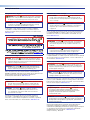
Safety Instructions
Safety Instructions • English
WARNING: This symbol, , when used on the product, is intended to
alert the user of the presence of uninsulated dangerous voltage within
the product’s enclosure that may present a risk of electric shock.
ATTENTION: This symbol, , when used on the product, is intended
to alert the user of important operating and maintenance (servicing)
instructions in the literature provided with the equipment.
For information on safety guidelines, regulatory compliances, EMI/EMF
compatibility, accessibility, and related topics, see the Extron Safety and
Regulatory Compliance Guide, part number 68-290-01, on the Extron website,
www.extron.com.
Sicherheitsanweisungen • Deutsch
WARUNG: Dieses Symbol auf demProdukt soll den Benutzer darauf
aufmerksam machen, dass im Inneren des Gehäuses dieses Produktes
gefährliche Spannungen herrschen, die nicht isoliert sind und die einen
elektrischen Schlag verursachen können.
VORSICHT: Dieses Symbol auf dem Produkt soll dem Benutzer in
der im Lieferumfang enthaltenen Dokumentation besonders wichtige
Hinweise zur Bedienung und Wartung (Instandhaltung) geben.
Weitere Informationen über die Sicherheitsrichtlinien, Produkthandhabung,
EMI/EMF-Kompatibilität, Zugänglichkeit und verwandte Themen finden Sie in den
Extron-Richtlinien für Sicherheit und Handhabung (Artikelnummer
68-290-01) auf der Extron-Website, www.extron.com.
Instrucciones de seguridad • Español
ADVERTENCIA: Este símbolo, , cuando se utiliza en el producto, avisa
al usuario de la presencia de voltaje peligroso sin aislar dentro del
producto, lo que puede representar un riesgo de descarga eléctrica.
ATENCIÓN: Este símbolo, , cuando se utiliza en el producto,
avisa al usuario de la presencia de importantes instrucciones de
uso y mantenimiento estas estan incluidas en la documentación
proporcionada con el equipo.
Para obtener información sobre directrices de seguridad, cumplimiento
de normativas, compatibilidad electromagnética, accesibilidad y temas
relacionados, consulte la Guía de cumplimiento de normativas y seguridad de
Extron, referencia 68-290-01, en el sitio Web de Extron, www.extron.com.
Instructions de sécurité • Français
AVERTISSEMENT : Ce pictogramme, , lorsqu’il est utilisé sur le
produit, signale à l’utilisateur la présence à l’intérieur du boîtier du
produit d’une tension électrique dangereuse susceptible de provoquer
un choc électrique.
ATTENTION : Ce pictogramme, , lorsqu’il est utilisé sur le produit,
signale à l’utilisateur des instructions d’utilisation ou de maintenance
importantes qui se trouvent dans la documentation fournie avec
l’équipement.
Pour en savoir plus sur les règles de sécurité, la conformité à la réglementation,
la compatibilité EMI/EMF, l’accessibilité, et autres sujets connexes, lisez les
informations de sécurité et de conformité Extron, réf. 68-290-01, sur le site
Extron, www.extron.com.
Istruzioni di sicurezza • Italiano
AVVERTENZA: Il simbolo, , se usato sul prodotto, serve ad avvertire
l’utente della presenza di tensione non isolata pericolosa all’interno
del contenitore del prodotto che può costituire un rischio di scosse
elettriche.
ATTENTZIONE: Il simbolo, , se usato sul prodotto, serve ad avvertire
l’utente della presenza di importanti istruzioni di funzionamento e
manutenzione nella documentazione fornita con l’apparecchio.
Per informazioni su parametri di sicurezza, conformità alle normative,
compatibilità EMI/EMF, accessibilità e argomenti simili, fare riferimento alla Guida
alla conformità normativa e di sicurezza di Extron, cod. articolo 68-290-01, sul
sito web di Extron, www.extron.com.
Instrukcje bezpieczeństwa • Polska
OSTRZEŻENIE: Ten symbol, , gdy używany na produkt, ma na celu
poinformować użytkownika o obecności izolowanego i niebezpiecznego
napięcia wewnątrz obudowy produktu, który może stanowić zagrożenie
porażenia prądem elektrycznym.
UWAGI: Ten symbol, , gdy używany na produkt, jest przeznaczony do
ostrzegania użytkownika ważne operacyjne oraz instrukcje konserwacji
(obsługi) w literaturze, wyposażone w sprzęt.
Informacji na temat wytycznych w sprawie bezpieczeństwa, regulacji wzajemnej
zgodności, zgodność EMI/EMF, dostępności i Tematy pokrewne, zobacz Extron
bezpieczeństwa i regulacyjnego zgodności przewodnik, część numer 68-290-01,
na stronie internetowej Extron, www.extron.com.
Инструкция по технике безопасности • Русский
ПРЕДУПРЕЖДЕНИЕ: Данный символ, , если указан
на продукте, предупреждает пользователя о наличии
неизолированного опасного напряжения внутри корпуса
продукта, которое может привести к поражению
электрическим током.
ВНИМАНИЕ: Данный символ, , если указан на продукте,
предупреждает пользователя о наличии важных инструкций по
эксплуатации и обслуживанию в руководстве, прилагаемом к
данному оборудованию.
Для получения информации о правилах техники безопасности,
соблюдении нормативных требований, электромагнитной
совместимости (ЭМП/ЭДС), возможности доступа и других вопросах
см. руководство по безопасности и соблюдению нормативных
требований Extron на сайте Extron: , www.extron.com,
номер по каталогу - 68-290-01.

Copyright
© 2022 - 2023 Extron. All rights reserved.
Trademarks
All trademarks mentioned in this guide are the properties of their respective owners.
The following registered trademarks®, registered service marks(SM), and trademarks(™) are the property of RGBSystems, Inc. or Extron (see the
current list of trademarks on the Terms of Use page at www.extron.com):
Registered Trademarks (®)
Cable Cubby, ControlScript, CrossPoint, DTP, eBUS, EDID Manager, EDID Minder, Extron, eLink, Flat Field, FlexOS, Glitch Free,
Global Configurator, Global Scripter, GlobalViewer, Hideaway, HyperLane, IP Intercom, IP Link, Key Minder, LinkLicense, LockIt, MediaLink,
MediaPort, NAV, NetPA, PlenumVault, PoleVault, PowerCage, PURE3, Quantum, ShareLink, Show Me, SoundField, SpeedMount, SpeedSwitch,
StudioStation, System INTEGRATOR, TeamWork, TouchLink, V-Lock, VideoLounge, VN-Matrix, VoiceLift, WallVault, WindoWall, XPA, XTP, XTP
Systems, and ZipClip.
Registered Service Mark(SM) : S3 Service Support Solutions
Trademarks (™)
AAP, AFL (Accu-RATE Frame Lock), ADSP (Advanced Digital Sync Processing), AVEdge, CableCover, CDRS (Class D Ripple Suppression),
Codec Connect, DDSP (Digital Display Sync Processing), DMI (Dynamic Motion Interpolation), Driver Configurator, DSP Configurator, DSVP
(Digital Sync Validation Processing), EQIP, Everlast, FastBite, Flex55, FOX, FOXBOX, IP Intercom HelpDesk, MAAP, MicroDigital, Opti-Torque,
PendantConnect, ProDSP, QS-FPC (QuickSwitch Front Panel Controller), Room Agent, Scope-Trigger, SIS, Simple Instruction Set, Skew-Free,
SpeedNav, Triple-Action Switching, True4K, True8K, Vector™ 4K, WebShare, XTRA, and ZipCaddy
안전 지침 • 한국어
경고: 이 기호 가 제품에 사용될 경우, 제품의 인클로저 내에 있는
접지되지 않은 위험한 전류로 인해 사용자가 감전될 위험이 있음을
경고합니다.
주의: 이 기호 가 제품에 사용될 경우, 장비와 함께 제공된 책자에 나와
있는 주요 운영 및 유지보수(정비) 지침을 경고합니다.
안전 가이드라인, 규제 준수, EMI/EMF 호환성, 접근성, 그리고 관련 항목에 대한
자세한 내용은 Extron 웹 사이트(www.extron.com)의 Extron 안전 및 규제 준수
안내서, 68-290-01 조항을 참조하십시오.
安全说明 • 简体中文
警告:产品上的这个标志意在警告用户, 该产品机壳内有暴露的危险
电 压 ,有 触 电 危 险 。
注意:产品上的这个标志意在提示用户, 设备随附的用户手册中有重
要的操作和维护(维修)说明。
关于我们产品的安全指南、遵循的规范、EMI/EMF 的兼容性、无障碍使
用的特性等相关内容,
敬请访问 Extron 网站 , www.extron.com,参见 Extron 安全规范指南,产品编号
68-290-01。
安全記事 • 繁體中文
警告: 若產品上使用此符號,是為了提醒使用者,產品機殼內存在未隔離的危
險電壓,可能會導致觸電之風險。
注意 若產品上使用此符號,是為了提醒使用者,設備隨附的用戶手冊中有重
要 的 操 作 和 維 護( 維 修 )説 明 。
有關安全性指導方針、法規遵守、EMI/EMF 相容性、存取範圍和相關主題的詳細資訊,
請瀏覽 Extron 網站:www.extron.com,然後參閱《Extron 安全性與法規遵守手
冊》,準則編號 68-290-01。

FCC Class B Notice
NOTE: This device complies with part 15 of the FCC rules. Operation is subject to the
following two conditions: (1) This device may not cause harmful interference, and (2)
This device must accept any interference received, including interference that may
cause undesired operation.
This equipment has been tested and found to comply with the limits for a Class B digital device,
pursuant to part15 of the FCC rules. These limits provide reasonable protection against harmful
interference in a residential installation. This equipment generates, uses, and can radiate radio
frequency energy and, if not installed and used in accordance with the instructions, may cause
harmful interference to radio communications. There is no guarantee that interference will not
occur. If this equipment does cause interference to radio or television reception, which can
be determined by turning the equipment off and on, you are encouraged to try to correct the
interference by one or more of the following measures:
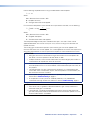
• Reorient or relocate the receiving antenna.
• Increase the separation between the equipment and receiver.
• Connect the equipment into an outlet on a circuit different from that to which the receiver is
connected.
• Consult the dealer or an experienced radio/TV technician for help.
In order to maintain compliance with FCC regulations, shielded cables must be used with this
equipment. Operation with non-approved equipment or unshielded cables is likely to result in
interference to radio and TV reception. The user is cautioned that changes and modifications
made to the equipment without the approval of the manufacturer could void the user’s authority
to operate this equipment.
NOTE: For more information on safety guidelines, regulatory compliances, EMI/EMF
compatibility, accessibility, and related topics see the Extron Safety and Regulatory
Compliance Guide on the Extron website.

Conventions Used in this Guide
Notifications
In this user guide, the following are used:
WARNING: Potential risk of severe injury.
ATTENTION : Risque potentiel de blessure grave ou de mort.
CAUTION: Risk of minor personal injury.
ATTENTION : Risque de blessuremineure.
ATTENTION:
• Risk of property damage.
• Risque de dommages matériels.
NOTE: A note draws attention to important information.
Specifications Availability
Product specifications are available on the Extron website, www.extron.com.
Extron Glossary of Terms
A glossary of terms is available at www.extron.com/technology/glossary.aspx.


Contents
Introduction............................................................ 1
About this Guide .....................................................1
Terms Used in this Guide ....................................1
Features .................................................................. 1
Application Example ................................................3
Installation .............................................................. 4
Tabletop Mounting ..................................................4
Rack Mounting ........................................................4
UL Guidelines for Rack Mounting ........................4
Consignes UL pour le montage en rack ..............5
Rack Mounting ....................................................5
Rack Mounting Ventilation Recommendations .....6
Accessing Fan Filters ..............................................7
Operation ................................................................ 8
Front Panel Features and Operation ........................8
Rear Panel Features and Operation ......................... 9
Power ...............................................................10
Indicators and Settings .....................................10
Connections .....................................................11
Defeating the Standby Timer .............................12
Operation .............................................................. 13
High Impedance Modes (70V or 100V) .............. 13
Low Impedance Modes (8Ω or 4Ω) ...................14
Appendix ..........................................................14
Troubleshooting ....................................................17
Amplifier Fails to Exit Standby Mode Promptly ...17
Amplifier Enters Standby Mode Too Early ..........17
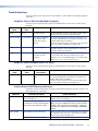
Limiter/Protect LED Warning Indicators ............. 17
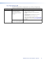
Over Temp Indicator LED ..................................18
XPA Ultra FX Series Power Amplifiers • Contents vii


Introduction
• About this Guide
• Features
• Application Example
About this Guide
This guide contains information about the Extron XPA Ultra FX Series of power amplifiers:
• XPA U 2004 FX
• XPA U 2008 FX
Terms Used in this Guide
The terms “amplifier” and “power amplifier” are used interchangeably in this manual to refer to
both the XPA U models.
Features
• Four (XPA U 2004 FX) or eight (XPA U 2008 FX) 200 watt channels into 8 ohms, 4
ohms, 70V, or 100V — These amplifiers are designed for large, high-powered multizone
integration projects.
• Configurable output mode per channel — Allows this single amplifier model to be used
in multizone installations with unique configurations per channel.
• Flexible power allocation to match system requirements — 400 total watts is shared
between adjacent odd/even channel pairs to provide the right amount of power where it is
needed.
• InstaWake+ exits auto-standby mode in under 5 milliseconds — These models
include an auto-standby feature that automatically places the amplifier into standby after
25 minutes of inactivity, dramatically reducing power consumption. The amplifiers quickly
return to full power status in less than 5 ms upon signal detection, with minimal inrush
current. Auto-standby can be disabled if required.
• HPF selectable for 70V and 100V channel modes — Prevents saturation of speaker
transformer cores.
• Rack-mountable 1U, full rack width enclosure — With the capability to deliver high
performance in one rack space, the amplifiers reduce rack space requirements for many
installations.
• Rear rack mounts included — The included rear rack mounts are easy to install and
provide additional stability.
• Front to rear fan-cooled — Includes washable and replaceable foam air filters.
• Rotary output mode selection switches — Easily, quickly, and reliably select the required
output mode.
• Professional grade signal-to-noise and THD+N performance — The amplifiers deliver
professional grade performance, featuring 100 dB signal-to-noise ratio and THD+N of less
than 0.1%.
• Ultra low inrush current at power up - no need for power sequencing — Allows
multiple XPA Ultra FX series amplifiers to be powered on simultaneously without overloading
power circuits.
XPA Ultra FX Series Power Amplifiers • Introduction 1

• Power factor correction - removes harmonic content on AC line — These amplifiers
feature power factor correction technology that smooths out the high peak currents of the
amplifier current draw, minimizing the presence of high frequency harmonics on the AC
power line, preventing audible artifacts from being transmitted to other audio equipment in
the system.
• Rear panel recessed, detented level controls — Provides attenuation of input signals for
adjusting audio system gain staging. These controls are located on the rear panel to prevent
tampering with level adjustments. Laser etched markings provide enhanced visibility of
settings for ease of configuration.
• Remote standby port — Enables the amplifiers to be remotely powered down when not in
use, reducing operating cost.
• Automatic clip limiter — Detects actual onset of clipping. Gain is automatically reduced
without audible artifacts to protect speakers from clipping distortion.
• Multiple protection circuits — Activate during output shorts, thermal overload, or DC
faults to prevent damage to the amplifier and speakers.
• 5 mm screw-lock captive screw speaker connectors — Enable simple, secure
connections with 22 to 12 AWG speaker cables.
• Front and rear-mounted signal and protection indication LEDs — Provide convenient
indication of input signal presence and protection circuit activation from both sides of an
equipment rack.
• Front panel over-temperature LED — Provides visual indication that the amplifier
temperature has exceeded the optimal value, well in advance of the onset of thermal
protection circuitry.
• Internal Extron Everlast power supply — Provides worldwide power compatibility, with
high-demonstrated reliability and low power consumption for reduced operating cost.
Extron Everlast Power Supply is covered by a 7-year parts and labor warranty.
XPA Ultra FX Series Power Amplifiers • Introduction 2

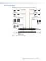
Application Example
The following illustration shows an example of an XPA U FX Series application.
Figure 1. XPA U Application Example
XPA Ultra FX Series Power Amplifiers • Introduction 3

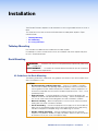
Installation
The XPA Ultra FX Series amplifiers can be mounted in a rack using included rack ears or set on a
table.
This section discusses how to install the XPA Ultra Series of audio power amplifiers. Topics
covered include:
• Tabletop Mounting
• Rack Mounting
• Accessing Fan Filters
Tabletop Mounting
Four self-adhesive rubber feet are included with the audio amplifier.
For tabletop use, attach one foot at each corner on the bottom side of the amplifier and place
the unit in the desired location.
Rack Mounting
WARNING: Installation and service must be performed by experienced, professional
installers only.
AVERTISSEMENT : L’installation et l’entretien doivent être effectués par des installateurs
professionnels expérimentés.
UL Guidelines for Rack Mounting
The following Underwriters Laboratories (UL) guidelines are relevant to the safe installation of the
XPA U FX amplifier in a rack:
CAUTION:
• Elevated operating ambient temperature — If the unit is installed in a closed or
multi-unit rack assembly, the operating ambient temperature of the rack environment
may be greater than room ambient temperature. Therefore, install the equipment in an
environment compatible with the maximum ambient temperature (Tma: +122°F, +50°C)
specified by Extron.
• Reduced air flow — Install the equipment in the rack so that the equipment gets
adequate air flow for safe operation.Mechanical loading — Mount the equipment in the
rack so that uneven mechanical loading does not create a hazardous condition.
• Mechanical loading — Mount the equipment in the rack so that uneven mechanical
loading does not create a hazardous condition.
• Circuit overloading — Connect the equipment to the supply circuit and consider the
effect that circuit overloading might have on overcurrent protection and supply wiring.
Consider the equipment nameplate ratings when addressing this concern
• Reliable earthing (grounding) — Maintain reliable grounding of rack-mounted
equipment. Pay particular attention to supply connections other than direct connections
to the branch circuit (such as the use of power strips).
XPA Ultra FX Series Power Amplifiers • Installation 4

Consignes UL pour le montage en rack
Les consignes UL (« Underwriters Laboratories ») suivantes concernent l’installation en rack d’un
boîtier XPA U FX :
ATTENTION :
• Température ambiante élevée — En cas d’installation de l’équipement dans un rack
fermé ou composé de plusieurs unités, la température du rack peut être supérieure
à la température ambiante. Par conséquent, il est préférable d’installer l’équipement
dans un environnement qui respecte la température ambiante maximale (Tma: +122°F,
+50°C) spécifiée par Extron
• Réduction du flux d’air — Si l’équipement est installé dans un rack, veillez à ce que le
flux d’air nécessaire pour un fonctionnement sécurisé de l’équipement soit respecté.
• Charge mécanique — Installez l’équipement en rack de manière à éviter toute
situation dangereuse causée par le déséquilibre de la charge mécanique.
• Surcharge électrique — Lorsque vous connectez l’équipement au circuit
d’alimentation, observez la connexion de l’équipement et étudiez les effets possibles
d’une surcharge du circuit sur les protections contre les surintensités et les conducteurs
d’alimentation. Consultez à cet égard les indications de la plaque d’identification de
l’équipement.
• Mise à la terre — Assurez-vous que l’équipement est correctement mis à la terre.
Accordez une attention particulière aux connexions électriques autres que les
connexions directes au circuit de dérivation (ex. : les multiprises).
Rack Mounting
Before mounting the amplifiers, ensure that power to the amplifier is turned off.
Turn off all other equipment and disconnect the power cables. Verify that the amplifier is
disconnected from the power source before proceeding.
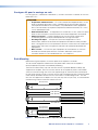
The XPA U Full-Rack Series ships with two rear rack ears to provide additional stability and
support for the amplifier. Each rear rack ear attaches to the amplifier by means of two SEMS
screws that connect though slots in the two support flanges on the enclosure that extend past
the rear panel, through the slots in the rear rack ear and into the backing plate. The backing plate
comes loosely attached to the rear rack ear, which allows it to slide along the slots. The rear
rack ears will support rack rail depths of 15.48" (393 mm) to 26.13" (664 mm), as measured from
outward-facing surfaces of the front and rear rack rails.
16.49" (419 mm)
26.34" (669 mm)
27.04" (687 mm)
16.39" (416 mm)
15.69" (399 mm)
15.48" (393 mm)
26.13" (664 mm)
Figure 2. XPA U Full-Rack Series Adjustable Rack Mounting Rails
XPA Ultra FX Series Power Amplifiers • Installation 5

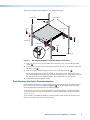
To install the amplifier into the equipment rack, follow these steps:
1
1
1
1
1
1
Screws
Front Rack Ear
3
3
3
2
2
2
2
2
2
3
3
3
2
2
2
Screws
Rear Rack Ear
Equipment Rack
Rear Rack Rails
Front Rack Rails
Backing Plate
Figure 3. Attaching the Amplifier to the Front and Rear of the Rack
1. Attach the front rack ears of the ampifier to the front of the rack, using the four provided
screws (1).
2. Install the rear rack ears into the corresponding position on the rails on the back side of the
equipment rack (2).
3. Slide the screws in the backing plate into the slots in the support flanges (3).
Loosen the backing plate screws just enough to allow them to easily slide into the slots in
the support flanges without getting the washers caught between the flange and the rear rack
ear, but not so much that the backing plate is disassembled from the rear rack ear.
4. Tighten down the backing plate screws.
Rack Mounting Ventilation Recommendations
Excessive heat can decrease the optimal lifetime of the power amplifier. An over temp indicator
LED on the front panel of the amplifier (see figure 5, D, on page 8) lights red whenever the
recommended operating temperature has been exceeded.
To reduce the chances of an over temp condition, the XPA U amplifiers should be arranged in
a rack environment such that the environment around the amplifier does not reach or exceed
+122 °F (+50 °C).
These amplifiers are cooled by forced air, with front to back airflow. Care must be taken not to
obstruct the airflow at the intake and exhaust vents.
XPA Ultra FX Series Power Amplifiers • Installation 6

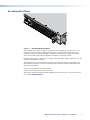
Accessing Fan Filters
Figure 4. Removing the Plastic Grille
The removable plastic grille assemblies (see figure 4) are secured to the steel front chassis by
two tabs on the inner edge that hook under the center UI section and are held in place by a
neodymium magnet on the outside edge. The grilles are removable by inserting the included
plastic removal tool into the front panel groove (see figure 4) and prying forward.
Each plastic grille covers a foam air filter. The filters are held in place inside the grille by crush ribs
along the inside edges of the grille.
To replace the filters, remove the grille from the front panel by inserting the included plastic pry
tool, flathead screwdriver, or other small flat object into the groove along the outer edge of the
grille and prying forward.
The filter can be removed, washed, and dried.
Reverse the procedure to reinstall the clean filter.
Alternatively, remove and replace the filter. Replacement air filter kits (AFK 100) are sold in packs
of 10 (see the Extron website).
XPA Ultra FX Series Power Amplifiers • Installation 7

Operation
This section discusses how to operate the XPA Ultra Series full-rack audio power amplifiers.
Topics covered include:
• Front Panel Features and Operation
• Rear Panel Features and Operation
• Operation
• Troubleshooting
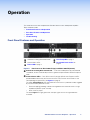
Front Panel Features and Operation
58761432
OVER TEMP
LIMITER/
PROTECT
SIGNAL
XPA U 2008 FX
POWER
4312
OVER TEMP
LIMITER/
PROTECT
SIGNAL
XPA U 2004 FX
POWER
CD EBA A
AGroove for inserting Grille removal tool DOver Temp LED on page 9
BChannel Status LEDs ERemovable Plastic Grilles on
page 9
CPower LED on page 9
Figure 5. Front Panels for XPA U 2004 FX (top) and XPA U 2008 FX (bottom)
A Groove for inserting Grille removal tool — Insert the included plastic pry tool, flathead
screwdriver, or other small flat object into this groove and pull forward to remove the plastic
Grille.
B Channel Status LEDs — Four (XPA U 2004 FX) or eight (XPA U 2008 FX) pairs of LEDs
provide feedback about the status of each channel. They have the same function as the
corresponding rear panel LEDs (see figure 6 on page 9).
The upper Limiter/Protect LEDs light red when the channel is in protection mode, triggered
by any of the limiter protection circuits:
• Excessive clipping (providing sufficient warning before the transformer cores in a high
impedance speaker system saturate).
• Short circuit on output
The lower Signal LEDs light green when the input signal crosses the signal detection
threshold.
figure 5
XPA Ultra FX Series Power Amplifiers • Operation 8

C Power LED (see figure 5 on page 8) — A single LED power indicator will light as
follows:
• Green when the unit is on and active
• Amber
• When the unit is in standby. Standby mode turns off all outputs from the amplifier,
although the amplifier is still receiving power.
• When DC voltage is detected on the output. This state is cleared only via reset/
power down. If it is not cleared via reset/power down, the unit may need to be
serviced.
D Over Temp LED — Lights red when the amplifier has exceeded the maximum
recommended operating temperature. The amplifier self-recovers once the unit has cooled
below the maximum recommended operating temperature.
Power limiting may or may not be applied at this point. This depends on the temperature of
the unit.
E Removable Plastic Grilles (2) — The removable plastic grille assembly is secured to the
steel front chassis by two tabs on the inner edge that hook under the center UI section and
are held in place by a neodymium magnet on the outside edge. The grilles are removable by
inserting the included plastic removal tool into the front panel groove and pulling forward.
Each plastic grille covers a foam air filter. The filters are held in place inside the grille by crush
ribs along the inside edges of the grille.
To replace the filters, remove the grille from the front panel by inserting the included plastic
pry tool, flathead screwdriver, or other small flat object into the groove along the outer edge
of the grille and pulling forward. Remove and wash or replace the filter.
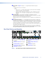
Rear Panel Features and Operation
XPA U 2004 FX
100-240V
~
--A, 50-60Hz
REMOTE
1
LIM/
PRT
(HPF OFF)
(HPF OFF)
70V70V
100V
100V
8Ω
4Ω
SIG
ATTENUAT IONOUTPUT MODE
0
12
4
6
8
10
12
18
14
26
∞
2
LIM/
PRT
(HPF OFF)
(HPF OFF)
70V70V
100V
100V
8Ω
4Ω
SIG
ATTENUAT IONOUTPUT MODE
0
12
4
6
8
10
12
18
14
26
∞
LIM/
PRT
(HPF OFF)
(HPF OFF)
70V70V
100V
100V
8Ω
4Ω
SIG
ATTENUAT IONOUTPUT MODE
0
12
4
6
8
10
12
18
14
26
∞
3
LIM/
PRT
(HPF OFF)
(HPF OFF)
70V70V
100V
100V
8Ω
4Ω
SIG
ATTENUAT IONOUTPUT MODE
0
12
4
6
8
10
12
18
14
26
∞
4
INPUTS
1234 GSTANDBY
1 2 3 4
OUTPUTS
XPA U 2008 FX
100-240V
~
4.0A, 50-60Hz
REMOTE
1
LIM/
PRT
(HPF OFF)
(HPF OFF)
70V70V
100V
100V
8Ω
4Ω
SIG
ATTENUAT IONOUTPUT MODE
0
12
4
6
8
10
12
18
14
26
∞
2
LIM/
PRT
(HPF OFF)
(HPF OFF)
70V70V
100V
100V
8Ω
4Ω
SIG
ATTENUAT IONOUTPUT MODE
0
12
4
6
8
10
12
18
14
26
∞
5
LIM/
PRT
(HPF OFF)
(HPF OFF)
70V70V
100V
100V
8Ω
4Ω
SIG
ATTENUAT IONOUTPUT MODE
0
12
4
6
8
10
12
18
14
26
∞
6
LIM/
PRT
(HPF OFF)
(HPF OFF)
70V70V
100V
100V
8Ω
4Ω
SIG
ATTENUAT IONOUTPUT MODE
0
12
4
6
8
10
12
18
14
26
∞
8
LIM/
PRT
(HPF OFF)
(HPF OFF)
70V70V
100V
100V
8Ω
4Ω
SIG
ATTENUAT IONOUTPUT MODE
0
12
4
6
8
10
12
18
14
26
∞
LIM/
PRT
(HPF OFF)
(HPF OFF)
70V70V
100V
100V
8Ω
4Ω
SIG
ATTENUAT IONOUTPUT MODE
0
12
4
6
8
10
12
18
14
26
∞
3
LIM/
PRT
(HPF OFF)
(HPF OFF)
70V70V
100V
100V
8Ω
4Ω
SIG
ATTENUAT IONOUTPUT MODE
0
12
4
6
8
10
12
18
14
26
∞
4
LIM/
PRT
(HPF OFF)
(HPF OFF)
70V70V
100V
100V
8Ω
4Ω
SIG
ATTENUAT IONOUTPUT MODE
0
12
4
6
8
10
12
18
14
26
∞
7
LIM/
PRT
(HPF OFF)
(HPF OFF)
70V70V
100V
100V
8Ω
4Ω
SIG
ATTENUAT IONOUTPUT MODE
0
12
4
6
8
10
12
18
14
26
∞
8
INPUTS
12345678GSTANDBY
5 6 7 81 2 3 4
OUTPUTS
XPA U 2004 FX (top) and XPA U 2008 FX (bottom)
AB
CD EF
GH
I
CLASS 2 WIRING
CLASS 2 WIRING
ARear Rack Ears (see Rack Mounting
on page 4)
FOutput Mode Selection Switch on
page 10
BIEC power connector (see page 10) GSpeaker output connectors on
page 11
CAC mains switch (see page 10) HLine inputs on page 11
DChannel Status LEDs (see page 10) IRemote Port on page 12
EAttenuators (see page 10)
Figure 6. XPA U 2004 FX (top) and XPA U 2008 FX (bottom) Rear Panel
Power LED
Over Temp LED
Removable Plastic Grilles
figure 6
XPA Ultra FX Series Power Amplifiers • Operation 9

Power
ATTENTION:
• The amplifier must be powered on last.
• L’amplificateur doit être mis sous tension en dernier.
Reconnect all power cables and switch on all other equipment before powering on the power
amplifier. The front panel power LED of the amplifier lights green.
B IEC power connector (see figure 6, on the previous page) — Connect this socket to
100 - 240 VAC, 50-60 Hz mains power supply.
C AC mains switch — Toggle this switch between power on and power off.
Indicators and Settings
D Channel Status LEDs — Four (XPA U 2004 FX) or eight (XPA U 2008 FX) pairs
of LEDs provide feedback about the status of each channel. They have the same
function as the corresponding front panel LEDs.
The upper Limiter/Protect (LIM/PRT) LEDs light red when the channel is in protection
mode, triggered by any of the limiter protection circuits:
• Excessive clipping (providing sufficient warning before the transformer cores in a
high impedance speaker system saturate).
• Short circuit on output
The lower Signal LEDs (SIG) light green when the input signal crosses the signal detection
threshold.
E Attenuators
Each channel has its own potentiometer that goes from full attenuation
(∞, fully counterclockwise) to no attenuation (0 dB, fully clockwise). Each
potentiometer is detented to more easily set the input signal level of
multiple channels to the same level of attenuation, and laser-etched to
indicate position. Use a small screwdriver (such as the provided Extron
Tweeker) to adjust the audio input level for the corresponding channel.
For information about adjusting the attenuation level of the XPA U amplifier, see Operation
on page 13.
F Output Mode Selection Switch — This switch determines the function
of each amplifier channel. There are six settings: two low-impedance (8
ohms, 4 ohms) and four high-impedance modes.
Low-Impedance Modes (8 ohm/4 ohm):
The 8 ohm stereo setting is used when connecting to 8 ohm speaker
loads, and the 4 ohm setting is used when connecting to 4 ohm loads.
High-Impedance Modes:
• There are four high-impedance modes available: 70V, 70V (HPF OFF), 100V, 100V
(HPF OFF). These modes are used when connecting to distributed 70 volt or 100 volt
loudspeaker systems.
• In the 70V and 100V modes, an 80Hz, 12 dB/octave high-pass filter is applied to the
signal, to prevent saturation of the transformer cores in the speakers.
• In the 70V (HPF OFF) and 100V (HPF OFF) modes, the high-pass filter is disabled. The
(HPF OFF) modes should only be used when a high-pass filter will be applied in a DSP
upstream of the amplifier.
IEC power connector
AC mains switch
LIM/
PRT
SIG
Channel Status LEDs
Attenuators
ATTENUATION
0
12
4
6
8
10
12
18
14
26
∞
(HPF OFF)
(HPF OFF)
70V 70V
100V
100V
8Ω
4Ω
OUTPUT MODE
Output Mode Selection Switch
XPA Ultra FX Series Power Amplifiers • Operation 10

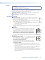
Connections
G Speaker output connectors
Wire the speakers to the amplifier output using the included 2-pole,
5.08 mm captive screw connectors (see figure 6, A). Each port has a
screw flange to secure the plug to the connector (B).
Do not tin the wires!
CLASS 2 WIRING
AB
Figure 7. Connecting Speaker Outputs
ATTENTION:
• Do not tie channel output pins to each other or to ground. Doing so will short out the
outputs, damage the amplifier, or both.
• Ne pas lier les sorties 1 et 2 des canaux entre elles ou à la terre. Les sorties
pourraient être court-circuitées et/ou l’amplificateur pourrait être endommagé.
• To avoid risk of damage to the amplifiers or speakers, ensure that the amplifier output
mode selection switch for each channel is properly configured to match the type of
speaker load about to be connected to the particular output.
• Pour éviter tout risque de détérioration des amplificateurs ou des enceintes, assurez-
vous que le switch de sélection du mode de sortie de l’amplificateur est correctement
configuré pour s’adapter au type de charge de l’enceinte qui sera connectée à la
sortie donnée.
NOTE: You must use Class 2 wiring for this output to comply with UL requirements.
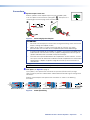
H Line inputs (see figure 6 on page 9)
Use 5-pole 3.5 mm captive screw connectors to input four (XPA U 2004 FX) or eight
(XPA U 2008 FX) channels of balanced or unbalanced line-level audio signals through these
connectors.
Wire the source output to the captive screw connectors as shown in the following
illustrations.
Balanced Stereo Input
Tip
Ring
Tip
Ring
Slee
ves
LR
Unbalanced Stereo Input
Tip
Sleeve
Sleeve
Tip
LR
Do not tin
the wires!
Balanced Dual Mono Input
Tip
Ring
Sleeve (s)
Tip
Ring
LR
Unbalanced Dual Mono Input
Tip
Sleeve
Tip
Sleeve
LR
Figure 8. Audio Input Wiring
Speaker output connectors
Line inputs
XPA Ultra FX Series Power Amplifiers • Operation 11

I Remote Port — Use the included 3.5 mm 2-pole captive screw
connector to connect the STANDBY pin to the G pin remotely.
This places the amplifier in standby mode.
The XPA U Full Rack Series amplifiers can enter standby mode
(reduced power state) if they meet one of the following two
conditions:
1. After 25 minutes (± 5 minutes) of inactivity (loss of signal)
2. Upon activation of the REMOTE port 10 kΩ
Resisto
r
2-pole Captive
Screw Connecto
r
To Control System
REMOTE
G
STANDBY
Remote Port
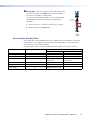
Defeating the Standby Timer
The standby timer can be disabled by wiring the supplied 10 kΩ resistor between the Standby
and Ground pins. The amplifier can still be forced into standby mode via the remote standby
port, even if the inactivity timer is disabled.
The following truth table summarizes the behavior of the amplifier in the various scenarios:
Remote Port Action Inactivity Timer Defeated? Time Since Last Detected Signal
Less than 25 minutes More than 25 minutes
No action (open) No Amplifier remains active Amplifier enters standby
Open to Close No Amplifier enters standby Amplifier remains in standby
Close to Open No Amplifier becomes active
Timer restarts
Amplifier becomes active
Timer restarts
No action (open) Yes Amplifier remains active -
Open to Close Yes Amplifier enters standby -
Close to Open Yes Amplifier becomes active -
XPA Ultra FX Series Power Amplifiers • Operation 12
La page est en cours de chargement...
La page est en cours de chargement...
La page est en cours de chargement...
La page est en cours de chargement...
La page est en cours de chargement...
La page est en cours de chargement...
La page est en cours de chargement...
-
 1
1
-
 2
2
-
 3
3
-
 4
4
-
 5
5
-
 6
6
-
 7
7
-
 8
8
-
 9
9
-
 10
10
-
 11
11
-
 12
12
-
 13
13
-
 14
14
-
 15
15
-
 16
16
-
 17
17
-
 18
18
-
 19
19
-
 20
20
-
 21
21
-
 22
22
-
 23
23
-
 24
24
-
 25
25
-
 26
26
-
 27
27


Extron XPA U 2004 FX Mode d'emploi
- Taper
- Mode d'emploi
- Ce manuel convient également à
Documents connexes
-
Extron XPA U 2002 SB Manuel utilisateur
-
-
-
-
-
-
-
-
Extron MPA 152 Plus Manuel utilisateur
-
Extron TLP 1000TV Manuel utilisateur
