
4-2162-01 Rev.J
ENGLISH ..............................1
CANADIEN FRANÇAIS ....15
ESPAÑOL ...........................31
®
DEL OZONE® 25/50/100
INSTALLATION INSTRUCTIONS & PRODUCT MANUAL
C-M-P.COM/DEL
®

IMPORTANT INFORMATION
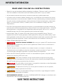
READ AND FOLLOW ALL INSTRUCTIONS
• Read this manual completely before attempting installation. Failure to install in accordance
with the installation instructions could void warranty and result in injury or death.
• All permanent electrical connections should be made by a qualified electrician.
• A pressure wire connector, labeled “bonding lug”, is provided on the outside of the unit to
permit connection to a minimum No. 6 AWG (13.3 mm2) solid bonding conductor between
this point and any metal equipment, metal enclosures of electrical equipment, metal water
pipes, or conduit within 5 feet (1.5 meters) of the unit as needed to comply with local
requirements.
• If the DEL Ozone generator electrical connection is to be attached to the pool controls, be
sure the pool controls are protected by a Ground Fault Circuit Interrupter (G.F.C.I.). If the DEL
Ozone generator is connected to an independent electrical supply, then a G.F.C.I. must be
installed between the DEL Ozone generator and the electrical supply.
• Install at least 5 feet (1.5 meters) from wall of pool using nonmetallic tubing. Tubing is
supplied with the DEL Ozone generator. Never replace this tubing with metal tubing. Install
ozone generator no less than one (1) foot above maximum water level to prevent water from
contacting electrical equipment. Install in accordance with the installation instructions.
• Follow all applicable electrical codes.
• DANGER ELECTRIC SHOCK HAZARD: Be sure to turn power OFF and disconnect
from power source before any service work is performed. Failure to do so could result in
serious injury or death.
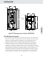
• The DEL Ozone® must be installed in an outdoor location, or indoors in a forced air
ventilated room, and installed so that the orientation is exactly as shown in Figure 1. Install
to provide water drainage of generator to protect electrical components.
• Mount the DEL Ozone® generator so that it is inaccessible to anyone in the pool. Never
attempt any servicing while unit is wet.
• WARNING Short-term inhalation of high concentrations of ozone and long term
inhalation of low concentrations of ozone can cause serious harmful physiological effects.
DO NOT inhale ozone gas produced by this device.
• DANGER For your safety, do not store or use gasoline, chemicals or other flammable
liquids or vapors near this or any other appliance.
• WARNING To reduce the risk of injury, do not permit children to use this product,
unless they are closely supervised at all times.
• WARNING If unit is not operated according to instructions, high dosages of harmful
substances may potentially be released.
• ENVIRONMENTAL NOTICE - Hg-Lamp CONTAINS MERCURY. Manage in accordance with
disposal laws. See: www.lamprecycle.org.
SAVE THESE INSTRUCTIONS!

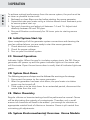
1 Overview
1A. Description .......................................................................................................1
1B. Specications ..................................................................................................1
2 Installation
2A. Location ............................................................................................................1
2B. Wall Mounting ...............................................................................................2
2C. Plumbing .........................................................................................................3
2D. Electrical ...........................................................................................................6
3 Operation
3A. General .............................................................................................................7
3B. Initial System Start-Up .................................................................................7
3C. Normal Operation ........................................................................................7
3D. System Shut-Down ....................................................................................... 7
3E. Water Chemistry ........................................................................................... 7
4 Maintenance & Service
4A. System Electromechanical Overview ......................................................8
4B. System Maintenance ....................................................................................8
4C. Generator Servicing .....................................................................................9
4D. Contact Informartion ................................................................................. 10
4E. Ordering Information ................................................................................ 10
4F. Replacement Parts ...................................................................................... 10
5 Troubleshooting .................................................................................................11
Appendix A: Installation Plumbing ................................................................ 13
TABLE OF CONTENTS

ENGLISH
1
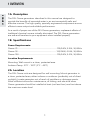
1A. Description
The DEL Ozone generators described in this manual are designed to
provide the benefits of ozonated water in an environmentally safe and
effective manner. The high quality, specially engineered components ensure
efficient ozone output and reliable performance.
As a result of proper use of the DEL Ozone generators, unpleasant effects of
traditional chemical use are virtually eliminated. The DEL Ozone generators
are safe and harmless to your equipment when installed properly.
1B. Specifications
Power Requirements:
Ozone 25 ..............................................................................120/240V, 0.10A, 50/60Hz
Ozone 50 .............................................................................120/240V, 0.24A, 50/60Hz
Ozone 100 ............................................................................. 120/240V, 0.31A, 50/60Hz
Location Requirements:
Mounting: Wall mount in a clean, protected area.
Ambient Temp.: 35°F - 120°F (2°C - 49°C)
2A. Location
The DEL Ozone units are designed for wall mounting. Mount generator in
a clean, protected area, either indoors or outdoors (preferably out of direct
sunlight). Locate generator out of reach of sprinklers or drainage spouts.
Allow sufficient access for maintenance, all tubing, and electrical wires.
Ozone generator should be installed at least (not less than) one foot above
the maximum water level.
1 OVERVIEW

ENGLISH
2
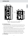
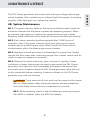
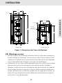
Ozone 100 Ozone 25 & 50
5.77”
3 x .25”
19.60”
2.68”
5.77”
Second
Cell Ozone
50 Only
2.68”
3 x .25”
12.40”
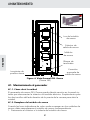
2B. Wall Mounting
1. Open the enclosure door and locate the three mounting holes on the
back wall of the enclosure. There will be two holes located near the top
on the left and right and one located in the center near the bottom.
Refer to Figure 1 for clarification.
2. Install screws (or other hardware appropriate for the mounting surface)
through the two mounting holes near the top of the enclosure. Install
the last screw through the mounting hole near the bottom of the
enclosure. Mounting hardware must be driven until the head fully
contacts the enclosure wall. Mounting hardware head must not be
smaller than 0.25 inches (6.3 mm) in diameter and the threads of the
hardware must be smaller than 0.25 inches (6.3 mm) in diameter.
2C. Plumbing
2 INSTALLATION
Figure 1: Mounting Hole Dimensions

ENGLISH
3
2 INSTALLATION
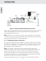
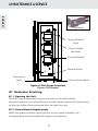
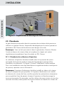
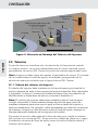
Figure 2: Injector Manifold Mounting Location
Chlorine
Feeder
Pump
from Pool Return
Filter Heater
Injector Manifold
DEL Ozone
Generator
Check
Valve OZONE
INJECTED
Ozone gas is introduced to the pool circulation line using a venturi injector.
Suction developed by the venturi allows the DEL Ozone generator to
operate safely under vacuum.
Note: Water must not travel back to the ozone generator. Mounting the
unit above the water line and scheduled check valve replacement will keep
water from entering the DEL Ozone generator.
2C-1. Plumbing the Injector Manifold
The injector manifold must be installed in the pool’s main return line after
all other pool equipment (pump, filter, heater, and cleaner). Figure 2 shows
the most basic installation. For installation with additional oxidizers and
pool cleaners, refer to Appendix A.
Note: The injector manifold should be installed above water level
whenever possible. If the injector manifold is installed below water level,
take proper precautions to prevent water from draining through the
injector and damaging the surrounding area. For example, use clamps
on all tube connections, run ozone tubing above water level and provide
adequate drainage around the pool equipment.
Locate an appropriate section of the return line and install the injector

ENGLISH
4
manifold with PVC cement. Be very careful to observe and follow the
correct water flow direction (as indicated by the arrow on the injector
manifold).
2C-2. Water Line Check Valve
If the pool equipment is mounted above the water line, a check valve must
be installed between the pump outlet and the injector manifold. This will
prevent the pump from draining and losing its prime (when not in use).
CMP HydroSeal™ check valve recommended.
2C-3. Pressure Test
If a pressure test is required, it should be performed prior to connecting the
ozone gas line. Install the 3/4” pipe cap provided onto the injector for the
pressure test.
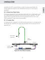
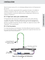
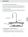
Figure 3a: Flow Meter Assembly
Add an arrow that points to the join of the
green ozone tube to the assembly, and
entitle it "Flow Meter Assembly:
Flow Meter
Assembly
Injector
Assembly
Tube
Adaptor
2 INSTALLATION

ENGLISH
5
2 INSTALLATION
2C-4. Flow Test - Refer to Figure 3a.
1. Install tube adapter on injector. Use Teflon thread tape as needed.
2. Connect the flow meter assembly to the tube adapter.
3. Hold the flow meter assembly so that the clear plastic chamber is
vertical with the tubing on top.
4. Turn on the pool’s circulation system as this allows the injector assembly
to pull a vacuum. Under normal operation, the ball in the flow meter
assembly will be floating in between its Max and Min line. Under worst-
case system conditions the flowmeter ball should indicate at least a
small amount of air flow. Flow may be adjusted as described below.
Manually Adjustable Injector Manifold: Gas flow can be controlled by
adjusting the valve on the manifold. Close the valve to increase gas flow,
open the valve to decrease gas flow.
Self-Adjusting Injector Manifold: This manifold is equipped with a
spring loaded valve. It cannot be manually adjusted, but provides a wide
operating range. If more gas flow is necessary, verify that other valves in
the system are not inhibiting flow through the manifold. If you experience
complications see TROUBLESHOOTING.
Add down arrow here with
the supporting text "Flow of
Check Valve"
Add arrow pointing to
the green square
between the ozone
tubes that says "Check
Valve Assembly"
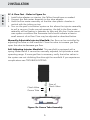
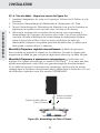
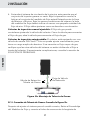
Check Valve
Flow of
Check Valve
Figure 3b: Ozone Tube Assembly
Ozone Tube

ENGLISH
6
2 INSTALLATION
2C-5. Ozone Tube Connection - Refer to Figure 3b.
After the system has been set for the correct flow rate, remove the flow
meter assembly and connect the ozone tube between the ozone outlet
barb on the DEL Ozone generator, and the tube adapter on the injector
assembly. Ensure that the check valve arrow is pointing toward the injector.
If equipment is above water level, cut off the excess tubing so that the line
from the injector to the DEL Ozone generator is as straight and free from
dips and loops as possible. If equipment is below the water level, run tubing
to a point above water level. Ensure that all tube connections are secured
with clamps.
2D. Electrical
2D-1. Main Power
This device is intended to be installed by a certified electrical technician, in
accordance with local electrical codes. Connect the DEL Ozone generator
to the pool timing clock so that the DEL Ozone generator operates
simultaneously with the pool pump. The DEL Ozone generator has three
available knockouts for a 1/2 inch conduit fitting, two on each side and
one on the back. Remove only the ideal knockout and install the proper
conduit fitting. Open the enclosure and locate the terminal block. Connect
Line 1, Line 2, and ground to the terminal block as indicated by the label
on the inside of the enclosure door. Refer to the IMPORTANT SAFETY
INSTRUCTIONS at the beginning of this manual for important wiring
information.
2D-2. Earth Grounding Lug
Using an 6 AWG (13.3 mm2) conductor, connect the grounding lug on the
bottom of the DEL Ozone generator to an appropriate earth contact.
3A. General

ENGLISH
7
To achieve optimal performance from the ozone system, the pool must be
as clean as possible to start with.
1. Backwash or clean filters one day before starting the ozone generator.
2. Superchlorinate pool water using a chlorine based shock treatment prior
to ozone system start-up.
3. Test pool chemistry and adjust pH between 7.4 and 7.6. Adjust total
alkalinity between 80 and 120 ppm.
4. Run pool filtration continuously for 24 hours prior to starting ozone
system.
3B. Initial System Start-Up
Upon completing all of the generator system connections and cleaning the
pool as outlined above, you are ready to start the ozone generator.
1. Check electrical connections.
2. Check for proper voltage.
3. Turn on pool circulation system.
3C. Normal Operation
Indicator Lights: When the pool’s circulation system starts, the DEL Ozone
generator will power up and the green indicator lights on the ozone cells
will illuminate. Open the enclosure door to verify that all indicator lights are
green.
3D. System Shut-Down
The following sequence of steps must be followed for servicing or for storage.
1. Disconnect the power to the ozone generator.
2. After the generator has been shut down, the pool water circulation
pump may be turned off.
3. If the system is to be shut down for an extended period, disconnect the
ozone tube from the unit.
3E. Water Chemistry
Regular chlorine or bromine testing should be performed as normal. Ozone
will be eliminating the majority of contaminants. Therefore, only a small
amount of chemicals will need to be added - just enough to maintain an
appropriate residual level of chlorine or bromine. Ozone is pH neutral thus
minimizing pH adjustments.
4A. System Electromechanical Overview- Ozone Module
3 OPERATION

ENGLISH
8
4 MAINTENANCE & SERVICE
The DEL Ozone generators are constructed with high voltage plasma gap
ozone modules. Each module has an indicator light that signals it’s working
properly. If the light goes out, replace the module.
4B. System Maintenance
4B-1. The green indicator lights on the ozone modules located inside the
enclosure indicate that the power supplies are operating properly. When
an indicator light goes out, replace the corresponding ozone module.
Regularly check inside the unit to verify all the ozone modules are working.
4B-2. Each ozone module should be replaced after 15,000 hours of
operation. Even if the green indicator light(s) are glowing, the ozone
module may be producing less ozone after this period of time due to
contamination within the plasma gap ozone chamber.
4B-3. Regularly reinstall and check the flowmeter for proper flow. Always
remove the flow meter after confirming proper flow. Inspect ozone tube for
cracks or wear and replace as necessary.
4B-4. Replace the ozone tube every year or sooner, if needed. If there
is evidence of water leaking past the check valve toward the DEL Ozone
generator, shut down the unit immediately and replace the ozone tube
and check valve. If water entered the DEL Ozone generator, allow the unit
to dry completely before restarting. Evidence of water in the DEL Ozone
generator may void the warranty.
WARNING Trace amounts of nitric acid may be present in the ozone
gas line. Wear proper safety equipment (gloves and eye protection)
and avoid direct contact with any condensation in the line.
4B-5. While operating, check to see if bubbles are entering the pool.
If an MDV is installed, check the MDV for bubbles.

ENGLISH
9
4C. Generator Servicing
4C-1. Opening the Unit
The DEL Ozone generator may be serviced on the wall without
disconnecting any of the plumbing or wiring. Simply remove the two screws
on the right side of the enclosure door to open the unit.
4C-2. Ozone Module Replacement
When the green indicator lights go out on the ozone modules, the
corresponding ozone module will need to be replaced.
4 MAINTENANCE & SERVICE
Grounding
Lugs Ozone Outlet Barb
Terminal Block
Ozone Module
Connector
Figure 4: DEL Ozone Overview
(Ozone 100 Shown)
Ozone Outlet
Manifold
Ozone Module
Light

ENGLISH
10
4 MAINTENANCE & SERVICE
To replace an Ozone Module:
1. Disconnect the manifold or tubing from the ozone module.
Note: For the Ozone 25 and Ozone 50, pull the tubing clamp back from
the ozone module barb connector, then pull the tubing from the barb.
2. Locate the ozone module power connector and disconnect it from the
wire harness.
3. Remove the ozone module mounting screws. The ozone module can
now be removed from the unit.
4. Install the new ozone module by reversing the steps.
4D. Contact Information
For technical assistance:
• Call: 1 (800) 733-9060
• Email: suppor[email protected]
• Or visit our website: www.c-m-p.com
4E. Ordering Information
To locate a dealer nearest you call 1 (800) 733-9060
or visit www.c-m-p.com.
Be prepared with the following information:
• Name
• Date Purchased
• Address
• Dealer Name
• Model #
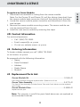
4F. Replacement Parts List:
Ozone Module Kit ............................................................................... 9-1636-01
Each ozone module should be replaced after 15,000 hours of use.
Ozone Tube Assembly .......................................................................9-0770-01
The Ozone Tube Assembly (includes Ozone Tube and Check Valve) must be replaced
once a year.
Ozone Module Filter ..........................................................................9-0858-01
Replace once a year.
Note: The warranty is void if the parts listed above are not replaced at
recommended intervals.

ENGLISH
11
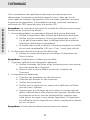
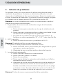
5. Troubleshooting
Knowledge of electrical applications is required for trouble shooting.
Contact a certified electrician if you are unsure of your ability to service
the equipment. Improper servicing will void generator warranty. If any
condition persists contact CMP technical support (see section 4D)
Symptom: Module Indicator Lights not lit when pool system is on.
1. No power to the ozone generator from the power source:
a. Check circuit breaker at the power distribution box.
b. Check for loose connections or wiring breaks from the power
distribution box to the generator.
c. The fuse in the unit has blown and needs to be replaced. The
fuse is a replaceable glass, .25” x 1.25”, 1 amp, slo-blo type.
2. G.F.C.I. has tripped.
a. Check power cord and reset G.F.C.I.
Symptom: Flowmeter not indicating flow.
1. Injector not supplying adequate suction.
a. Check pump, filters, and skimmers to ensure water is flowing
through injector.
b. Ensure that there is no debris clogged inside the injector.
2. Tubing is impaired.
a. Check for kinks or clogs.
b. Check for cracks or cuts.
c. Check connections.
d. Check that the check valve is installed with the arrow pointing
towards the injector.
e. Be sure that the check valve has not become fouled with debris.
Disconnect the ozone tube from the injector. With the pump
running, cover the end of the injector with your thumb, and feel
for suction. If there is sufficient suction without the check valve,
replace the check valve with a new one.
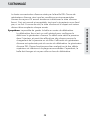
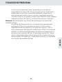
Symptom: Ozone tube becomes yellow/brown and brittle.
5 TROUBLESHOOTING

ENGLISH
12
The high concentration of ozone created by the DEL Ozone family
of ozone generators, as well as environmental conditions like UV
sunlight will tend to deteriorate the supplied ozone tube. This is
normal and acceptable, as long as the tubing doesn’t become
cracked and leak. Because of this, the ozone tube and check valve
should be replaced every year.
Symptom: Can’t get ball to stay in the center of flowmeter.
The flowmeter provided is a general tool to setup flow to the
ozone generator. Flow will vary depending on pressures across the
injector, and therefore can be affected by things such as filter or
strainer loading. The ozone generator’s efficiency is optimized near
the center of the flow meter. The DEL Ozone generator will still
perform well at flows above and below the recommended range.
However, the ball must be moving and not stuck on the bottom of
the flowmeter.
5 TROUBLESHOOTING

ENGLISH
13
4-1393-01_Rev.C
D
D
E
E
L
L
O
O
z
z
o
o
n
n
e
e
I
I
n
n
s
s
t
t
a
a
l
l
l
l
a
a
t
t
i
i
o
o
n
n
–
–
P
P
l
l
u
u
m
m
b
b
i
i
n
n
g
g
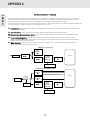
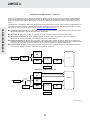
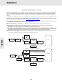
The DEL Ozone series generators work under vacuum. The injector manifold draws the ozone/air gas mixture out of the
ozone generator and mixes it into the water leaving behind some un-dissolved gas bubbles. These bubbles can affect
certain pool system components, so care must be taken when installing the ozone injector manifold.
The diagrams below cover common plumbing configurations. For other configurations or installation questions, please call
uP
P
o
o
o
o
l
l
C
C
l
l
e
e
a
a
n
n
e
e
r
r
s
s
: Always plumb the cleaner T-fitting before the DEL Ozone injector to prevent gas from affecting the
operation of the cleaner.
vS
S
a
a
l
l
t
t
C
C
h
h
l
l
o
o
r
r
i
i
n
n
a
a
t
t
o
o
r
r
:
:
A salt chlorinator may be plumbed on either side of the DEL Ozone injector.
w
w
C
C
h
h
l
l
o
o
r
r
i
i
n
n
e
e
T
T
a
a
b
b
/
/
M
M
i
i
n
n
e
e
r
r
a
a
l
l
E
E
r
r
o
o
s
s
i
i
o
o
n
n
F
F
e
e
e
e
d
d
e
e
r
r
:
:
Always plumb the DEL Ozone injector after any erosion feeder to avoid
gas accumulating in the feeder.
xI
I
n
n
-
-
F
F
l
l
o
o
o
o
r
r
C
C
l
l
e
e
a
a
n
n
i
i
n
n
g
g
S
S
y
y
s
s
t
t
e
e
m
m
:
:
The DEL Ozone Injector must be on a different pool return leg than any in-floor
cleaning system to avoid excess back pressure on the injector. This will also prevent gas intrusion and high oxidizer
levels in zone valve and cleaner heads.
yW
W
a
a
t
t
e
e
r
r
F
F
e
e
a
a
t
t
u
u
r
r
e
e
s
s
:
:
Avoid plumbing the injector manifold into any leg with excessive back pressure such as those
going to fountains, restrictive wall fittings, etc.
Heater
DEL
Ozone
Injector
Manifold
DEL Ozone
In-Floor
Cleaner
Pool
Sanitizer
To Spa
Sanitizer
Water
Features
Diagram 2: Pool/Spa Combo
Diagram 1: Pool Only
Actuator
Heater
Pool
Cleaner
DEL
Ozone
Injector
Manifold
DEL Ozone
Sanitizer
Pool
Sanitizer
Sanitizer
APPENDIX A

ENGLISH
14
NOTES
SAVE THESE INSTRUCTIONS
Record Information on this System Below & Keep for Your Records
Installer ______________________________________________________________
System Purchased From _____________________________________________
Installation Date _____________________________
Serial Number _______________________________
Model Number ______________________________
CMP Customer Service & Tech Support
Toll Free: 1-800-733-9060
FAX: 770-632-7115
suppor[email protected]
Warranty Questions

15
CANADIEN FRANÇAIS
Lisez et suivez toutes les instructions
• Lisez complètement ce manuel avant toute installation. Le fait de ne pas installer le produit en
conformité avec les instructions d’installation peut annuler la garantie et pourrait entraîner des
blessures ou la mort.
• Toutes les connexions électriques permanentes doivent être effectuées par un électricien qualifié.
• Un connecteur de fil à pression, étiqueté « cosse de connexion », est fourni sur l’extérieur de
l’appareil pour permettre de le relier à un conducteur de connexion solide No 6 AWG (13,3 mm2)
au minimum, entre ce point et tout équipement métallique, boîtiers métalliques d’équipement
électrique, tuyaux d’eau métalliques, ou conduit dans un rayon de 1,5 m (5 pi) de l’appareil comme
requis pour se conformer aux exigences locales.
• Si la connexion électrique du générateur DEL Ozone doit être attachée aux commandes de
la piscine, assurez-vous que les commandes de la piscine soient protégées par un disjoncteur
différentiel de fuite à la terre (DDFT). Si le générateur DEL Ozone est connecté à une alimentation
électrique indépendante, alors un DDFT doit être installé entre le générateur DEL Ozone et
l’alimentation électrique.
• Installer à au moins 1,5 m (5 pi) d’une paroi de piscine en utilisant du tubage non métallique. Le
tubage est fourni avec le générateur DEL Ozone. Ne jamais remplacer ce tubage par un tubage
métallique. Ne jamais installer le générateur d’ozone à moins de 0,30 m (1 pi) au-dessus du niveau
d’eau maximum afin d’empêcher l’eau d’entrer en contact avec l’équipement électrique. Installer
en conformité avec les instructions d’installation.
• Suivre les codes électriques applicables.
• Danger de choc électrique: Assurez-vous de couper l’alimentation et débrancher de la source
électrique avant que tout travail de service soit effectué. Le non-respect de cette consigne peut
engendrer des blessures graves ou entraîner la mort.
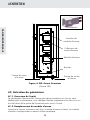
• Le DEL Ozone® doit être installé à l’extérieur, ou à l’intérieur dans une salle ventilée à air puisé,
et de façon à ce que l’orientation soit exactement comme dans la Figure 1. Installer pour fournir
une vidange d’eau afin de protéger les composants électriques.
• Monter le générateur DEL Ozone® afin qu’il ne soit accessible à personne qui se trouve dans la
piscine. Ne jamais essayer de maintenance lorsque l’appareil est mouillé.
• L’inhalation à court terme de concentrations élevées d’ozone et l’inhalation à long terme de
concentrations faibles d’ozone peuvent provoquer de graves effets physiologiques nocifs. NE
PAS inhaler le gaz d’ozone produit par cet appareil.
• Pour votre sécurité, ne pas entreposer ou utiliser de l’essence, des produits chimiques ou d’autres
liquides ou vapeur inflammables près de celui-ci ou de tout autre appareil ménager.
• Pour réduire le risque de blessures, ne pas permettre aux enfants d’utiliser ce produit, à moins
qu’ils soient étroitement surveillés durant toute l’utilisation.
• Si l’appareil n’est pas utilisé en conformité avec les instructions, des doses élevées de substances
toxiques peuvent potentiellement être libérées.
• AVIS ENVIRONNEMENTAL- L’ampoule Hg-CONTIENT DU MERCURE. Gérer en conformité avec
les lois sur l’élimination. Voir : www.lamprecycle.org.
CONSERVEZ CES INSTRUCTIONS!
INSTRUCTIONS IMPORTANTES

16
CANADIEN FRANÇAIS
TABLE DES MATIÈRES
1 Vue d’ ensemble
1A. Description .................................................................................................... 17
1B. Spécications ............................................................................................... 17
2 Installation
2A. Emplacement ............................................................................................... 17
2B. Montage au mur ......................................................................................... 18
2C. Plomberie ...................................................................................................... 19
2D. Électricité .......................................................................................................22
3 Functionnement
3A. Général ..........................................................................................................23
3B. Démarrage du système initial .................................................................23
3C. Fonctionnement normal ...........................................................................23
3D. Arrêt du système ........................................................................................23
3E. pH de l’eau....................................................................................................23
4 Entretien
4A. Vue d’ensemble électromécanique du système .............................. 24
4B. Entretien du système ................................................................................ 24
4C. Entretien du générateur ...........................................................................25
4D. Coordonnées ...............................................................................................26
4E. Informations sur les commandes ..........................................................26
4F. Liste standard des pièces de rechange ...............................................26
5 Dépannage ............................................................................................................ 27

17
CANADIEN FRANÇAIS
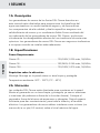
1A. Description
Les générateurs d’ozone DEL Ozone Series décrits dans ce manuel visent
à offrir les avantages d’eau ozonée de manière efficace et écologique. Les
composants de haute-qualité, fabriqués spécialement pour assurer une
production d’ozone efficace et une performance fiable.
Une utilisation correcte des générateurs d’ozone DEL Ozone, éliminent
virtuellement tout effet désagréable lié à l’utilisation traditionnelle de
produits chimiques. Les générateurs d’ozone DEL Ozone sont sans danger
pour votre équipement s’ils sont installés correctement.
1B. Spécifications
Exigences d’alimentation électrique:
Ozone 25 .....................................120/240V, 0.10A max, 50/60Hz
Ozone 50 .....................................120/240V, 0.24A max, 50/60Hz
Ozone 100 ....................................120/240V, 0.31A max, 50/60Hz
Exigences relatives à l’emplacement:
Montage: monter au mur dans une zone propre et protégée.
Température ambiante: entre 2°C et 49°C
2A. Emplacement
Les unités DEL Ozone sont conçues pour un montage au mur. Montez le
générateur dans une zone propre et protégée, à l’intérieur ou à l’extérieur (de
préférence à l’abri de la lumière directe du soleil). Placez le générateur hors de
la portée des arroseurs automatiques ou des évacuations d’eau. Permettez un
accès suffisant pour l’entretien des conduites et fils électriques. Le générateur
d’ozone doit être installé à au moins (minimum) 0,3 mètres au-dessus du
niveau maximum de l’eau.
1 VUE D’ENSEMBLE
La page est en cours de chargement...
La page est en cours de chargement...
La page est en cours de chargement...
La page est en cours de chargement...
La page est en cours de chargement...
La page est en cours de chargement...
La page est en cours de chargement...
La page est en cours de chargement...
La page est en cours de chargement...
La page est en cours de chargement...
La page est en cours de chargement...
La page est en cours de chargement...
La page est en cours de chargement...
La page est en cours de chargement...
La page est en cours de chargement...
La page est en cours de chargement...
La page est en cours de chargement...
La page est en cours de chargement...
La page est en cours de chargement...
La page est en cours de chargement...
La page est en cours de chargement...
La page est en cours de chargement...
La page est en cours de chargement...
La page est en cours de chargement...
La page est en cours de chargement...
La page est en cours de chargement...
La page est en cours de chargement...
La page est en cours de chargement...
La page est en cours de chargement...
La page est en cours de chargement...
-
 1
1
-
 2
2
-
 3
3
-
 4
4
-
 5
5
-
 6
6
-
 7
7
-
 8
8
-
 9
9
-
 10
10
-
 11
11
-
 12
12
-
 13
13
-
 14
14
-
 15
15
-
 16
16
-
 17
17
-
 18
18
-
 19
19
-
 20
20
-
 21
21
-
 22
22
-
 23
23
-
 24
24
-
 25
25
-
 26
26
-
 27
27
-
 28
28
-
 29
29
-
 30
30
-
 31
31
-
 32
32
-
 33
33
-
 34
34
-
 35
35
-
 36
36
-
 37
37
-
 38
38
-
 39
39
-
 40
40
-
 41
41
-
 42
42
-
 43
43
-
 44
44
-
 45
45
-
 46
46
-
 47
47
-
 48
48
-
 49
49
-
 50
50


CMP DEL OZONE® 25/50/100 Le manuel du propriétaire
- Taper
- Le manuel du propriétaire
- Ce manuel convient également à
dans d''autres langues
Documents connexes
Autres documents
-
Pentair 320 Guide d'installation
-
Ozone SC-OZ/2 Le manuel du propriétaire
-
 Mi-T-M WTR SERY Le manuel du propriétaire
-
Jandy LXI Mode d'emploi
-
Jacuzzi AIR BATHS LUXURY SERIES Manuel utilisateur
-
Marquis Everyday Hot Tub Le manuel du propriétaire
-
Teledyne API T200U/NOy Manuel utilisateur
-
-
 Cal Spas Portable Spas Le manuel du propriétaire
-

