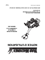
MTD 450 Manuel utilisateur
- Catégorie
- Mini motoculteurs
- Taper
- Manuel utilisateur
Ce manuel convient également à

IMPORTANT: READ
MTD PRODUCTS LTD. P.O. BOX 1386 KITCHENER, ON N2G 4J1
REAR TINE
TILLER
MODEL
450 Series
PRINTED IN THE U.S.A.
772C0731
SAFETY RULES AND
INSTRUCTIONS CAREFULLY
(10/04)
OPERATOR’S MANUAL

2
TABLE OF CONTENTS
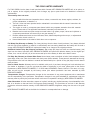
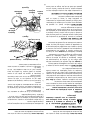
FINDING MODEL NUMBER
This Operator’s Manual is an important part of your new equipment. It will help you assemble, prepare and maintain the unit for
best performance. Please read and understand what it says.
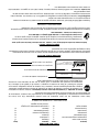
Before you start assembling your new equipment, please locate the model plate on the equipment and copy the
information from it in the space provided below. A sample model plate is also given below. You can locate the model
plate by standing at the operating position and looking down at the rear of the deck . This information will be
necessary to use the manufacturer’s web site and/or help from the Customer Support Department or an authorized
service dealer.
ENGINE INFORMATION
The engine manufacturer is responsible for all engine-related issues with regards to performance, power-rating, specifications,
warranty and service. Please refer to the engine manufacturer’s Owner’s/Operator’s Manual packed separately with your unit for
more information.
CALLING CUSTOMER SUPPORT
Please do NOT return the unit to the retailer from which it was purchased, without first contacting Customer Support.
If you have difficulty assembling this product or have any questions regarding the controls, operation or maintenance
of this unit, please call a Customer Support Representataive.
For US Customers: 1- (330) 220-4MTD (4683) or 1- (800)-800-7310
For Canadian Customers: 1-800-668-1238
Please have your unit’s model number and serial number ready when you call. See previous section to locate this information.
You will be asked to enter the serial number in order to process your call.
HOW TO OBTAIN SERVICE
Service is available, WITH PROOF OF PURCHASE, through your local authorized service dealer. To locate the
dealer in your area;
In the U.S.A.
: Check your Yellow Pages, or contact customer support listed about MTD LLC at P.O. Box 361131,
Cleveland, Ohio 44136-0019, or call 1-800-800-7310 or 1-330-220-4683 or log on to our Web site at
www.mtdproducts.com.
In Canada
: Contact MTD Products Limited, Kitchener, ON N2G 4J1, or call 1-800-668-1238 or log on to our Web
site at www.mtdcanada.com.
Content Page
Customer Support 2
Important Safe Operation Practices 3
Loose Parts 5
Assembly 6
Controls 8
Operation 9
How To Use Your Tiller 10
Adjustments 11
Lubrication 11
Maintenance 11
Off-Season Storage 12
Trouble Shooting Guide 13
Parts Lists/Pièces détachées 14
Warranty 20
Content Page
MTD PRODUCTS LIMITED
KITCHENER, ON N2G 4J1
1-800-668-1238
XXXXXXXXXX
XXXXXXXXXXX
Model Number
Numéro de modèle
Serial Number
Numéro de série
www.mtdcanada.com
This is where your model number will be.
This is where your serial number will be.
Copy the model number here:
Copy the serial number here:

3
SECTION 1: IMPORTANT SAFE OPERATION PRACTICES
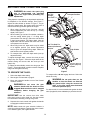
WARNING: This symbol points out important safety instructions which, if not followed, could endanger
the personal safety and/or property of yourself and others. Read and follow all instructions in this manual
before attempting to operate your tiller. Failure to comply with these instructions may result in personal
injury. when you see this symbol— HEED ITS WARNING
.
DANGER: Your tiller was built to be operated according to the rules for safe operation in this manual.
As with any type of power equipment, carelessness or error on the part of the operator can result in
serious injury. This tiller is capable of amputating hands and feet. Failure to observe the following safety
instructions could result in serious injury or death.
TRAINING
1. Read, understand, and follow all instructions on the
machine and in the manual(s) before attempting to
assemble and operate. Keep this manual in a safe
place for future and regular reference and for
ordering replacement parts.
2. Be familiar with all controls and their proper
operation. Know how to stop the machine and
disengage them quickly.
3. Never allow children under 14 years old to operate
this machine. Children 14 years old and over should
read and understand the operation instructions and
safety rules in this manual and should be trained
and supervised by a parent.
4. Never allow adults to operate this machine without
proper instruction.
5. Keep bystanders, helpers, children and pets at
least 75 feet from the machine while it is in
operation. Stop machine if anyone enters the area.
PREPARATION
1. Thoroughly inspect the area where the equipment
is to be used. Remove all stones, sticks, wire, and
other foreign objects which could be tripped over
and cause personal injury.
2. Wear sturdy, rough-soled work shoes and close-
fitting slacks and shirts. Loose fitting clothes and
jewelry can be caught in movable parts. Never
operate this machine in bare feet or sandals.
3. Disengage clutch levers and shift (if provided)
lever into neutral ("N") before starting the engine.
4. Never leave this machine unattended with the
engine running.
5. Never attempt to make any adjustments while the
engine is running, except where specifically
recommended in the operator’s manual.
6. To avoid personal injury or property damage use
extreme care in handling gasoline. Gasoline is
extremely flammable and the vapors are
explosive. Serious personal injury can occur when
gasoline is spilled on yourself or your clothes
which can ignite. Wash your skin and change
clothes immediately.
7. Use only an approved gasoline container.
8. Extinguish all cigarettes, cigars, pipes and other
sources of ignition.
9. Never fuel machine indoors.
10. Never remove gas cap or add fuel while the
engine is hot or running.
11. Allow engine to cool at least two minutes before
refueling.
12. Never over fill fuel tank. Fill tank to no more than
½ inch below bottom of filler neck to allow space
for fuel expansion.
13. Replace gasoline cap and tighten securely.
14. If gasoline is spilled, wipe it off the engine and
equipment. Move unit to another area. Wait 5
minutes before starting the engine.
15. Never store the machine or fuel container inside
where there is an open flame, spark or pilot light
as on a water heater, space heater, furnace,
clothes dryer or other gas appliances.
16. Allow a machine to cool at least 5 minutes before
storing.
OPERATION
1. Do not put hands or feet near rotating parts.
Contact with the rotating parts can amputate
hands and feet.
2. Do not operate the machine while under the
influence of alcohol or drugs.
3. Never operate this machine without good visibility
or light. Always be sure of your footing and keep a
firm hold on the handles.
4. Keep bystanders, helpers, children and pets at
least 75 feet from the machine while it is in
operation. Stop machine if anyone enters the area.
5. Be careful when tilling in hard ground. The tines
may catch in the ground and propel the tiller
forward. If this occurs, let go of the handle bars and
do not restrain the machine.
6. Exercise extreme caution when operating on or
crossing gravel surfaces. Stay alert for hidden
hazards or traffic. Do not carry passengers.
7. Never operate the machine at high transport
speeds on hard or slippery surfaces.
8. Exercise caution to avoid slipping or falling.

4
9. Look down and behind and use care when in
reverse or pulling machine towards you.
10. Start the engine according to the instructions
found in this manual and keep feet well away from
the tines at all times.
11. After striking a foreign object, stop the engine,
disconnect the spark plug wire(s) and ground
against the engine. Thoroughly inspect the
machine for any damage. Repair the damage
before starting and operating.
12. Disengage all clutch levers and stop the engine
before you leave the operating position (behind the
handles). Wait until the tines come to a complete
stop before unclogging the tines, making any
adjustments, or inspections.
13. Never run an engine indoors or in a poorly
ventilated area. Engine exhaust contains carbon
monoxide, an odorless, and deadly gas.
14. Muffler and engine become hot and can cause a
burn. Do not touch.
15. Use caution when tilling near fences, buildings and
underground utilities. Rotating tines can cause
property damage or personal injury.
16. Do not overload machine capacity by attempting to
till soil too deep at too fast of a rate.
17. If the machine should start making unusual noise
or vibration, stop the engine, disconnect the spark
plug wire and ground it against the engine. Inspect
thoroughly for damage. Repair any damage before
starting and operating.
18. Keep all shields, guards and safety devices in
place and operating properly.
19. Never pick up or carry machine while the engine is
running.
20. Use only accessories and attachments approved
for this machine by the machine manufacturer.
Failure to do so, can result in serious injury.
21. If situations occur which are not covered in this
manual, use care and good judgment. Contact
your authorized dealer for assistance.
MAINTENANCE & STORAGE
1. Never tamper with safety devices. Check their
proper operation regularly.
2. Check bolts and screws for proper tightness at
frequent intervals to keep the machine in safe
working condition. Also, visually inspect machine
for any damage.
3. Before cleaning, repairing, or inspecting, make
certain the tine(s) and all moving parts have
stopped. Disconnect the spark plug wire and
ground against the engine to prevent unintended
starting.
4. Do not change the engine governor settings or
over-speed the engine. The governor controls the
maximum safe operating speed of the engine.
5. Maintain or replace safety and instruction labels,
as necessary.
6. Follow this manual for safe loading, unloading,
transporting, and storage of this machine.
7. Never store the machine or fuel container inside
where there is an open flame, spark or pilot light
as on a water heater, space heater, furnace,
clothes dryer or other gas appliances.
8. Always refer to the operator’s manual for proper
instructions on off-season storage.
9. If the fuel tank has to be drained, do this outdoors.
10. Observe proper disposal laws and regulations for
gas, oil, etc. to protect the environment.
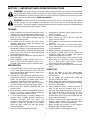
WARNING — YOUR RESPONSIBILITY: Restrict the use of this power machine to persons who read,
understand and follow the warnings and instructions in this manual and on the machine.
Figure 1 Safety labels found on your unit

5
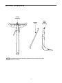
SECTION 2: LOOSE PARTS
Handle
Assembly
Depth
Stake
Assembly
Control
Rod
NOTE: All hardware needed for assembly is attached to the loose parts or the tiller.
NOTE: Cable tie not shown.

6
SECTION 3: ASSEMBLY INSTRUCTIONS
IMPORTANT: This unit is shipped WITHOUT
GASOLINE or OIL. After assembly, see separate
engine manual for proper fuel and engine oil
recommendations.
NOTE: Left and right is determined from the
operator’s position, standing behind the tiller.
TOOLS REQUIRED FOR ASSEMBLY
Adjustable Wrenches
Pair of Pliers
Screw Driver
TO REMOVE UNIT FROM CARTON
1. Remove staples, break glue on top flaps, or cut
tape at carton end and peel along top flap to open
carton.
2. Remove loose parts included with unit (i.e.,
operator’s manual, etc.).
3. Cut corners and lay carton down flat.
4. Remove packing material.
5. Roll or slide unit out of carton. Check carton
thoroughly for loose parts.
6. Extend control cable and lay on the floor. Be
careful not to bend or kink control cable.
Figure 1
WARNING: Disconnect the spark plug
wire and ground against the engine to
prevent unintended starting.
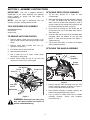
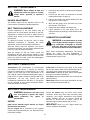
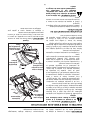
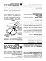
ATTACHING DEPTH STAKE ASSEMBLY
1. Tip the tiller forward so it rests on front
counterweight.
2. Raise the tine shield hinge flap assembly. Remove
"T" knob, flat washer and hex bolt from depth
stake. Insert the depth stake assembly in front of
spacer (under the tine shield) and up through the
tine shield assembly as shown in Figure 1.
3. Insert clevis pin through the tine shield and the
second hole from top of the depth stake. Secure
with hairpin clip.
4. Insert hex bolt into the top hole of the depth stake
assembly. Place flat washer on hex bolt and
thread “T” knob onto the hex bolt. See Figure 1.
Tighten securely.
5. Tip the tiller back down so it rests on the depth
stake (transport position).
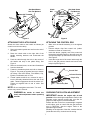
ATTACHING THE HANDLE ASSEMBLY
Figure 2
1. Remove top two bolts and flange lock nuts from
handle mounting brackets as shown in Figure 2.
Do not remove the bottom bolt and nut.
2. Place handle assembly in position between the
handle mounting brackets. See Figure 2.
3. Line up holes in handle with holes in handle
mounting brackets. Secure with hardware
removed in step 1.
T-Knob
Flat Washer
Hex Bolt
Hairpin Clip
Clevis Pin
Depth Stake
Rear Tine
Shield
Remove
Handle
Assembly
Handle
Bracket

7
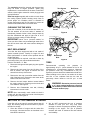
Figure 3
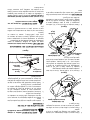
ATTACHING THE CLUTCH CABLE
Attach the clutch cable to the handle as follows (be
careful not to kink the cable).
1. Remove threaded eyebolt and nut from the end of
the cable.
2. Route the clutch cable to the right side of the
handle mounting brackets and underneath the
handle.
3. Push the cable through the hole in the center of
the handle and snap in the plastic fitting. See
Figure 3.
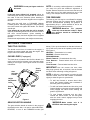
4. Remove slot head screw, nut and two flat washers
from the clutch bail.
5. Fasten the threaded eyebolt onto bail as shown in
Figure 4. The parts go together from top to bottom
as follows: Slot Head Screw, Flat Washer, Clip,
Eyebolt, Flat Washer and 1/4” Nut.
6. Thread eyebolt and #10 nut, removed in step 1,
into the internally threaded tube at the end of the
cable. Thread engagement should be about 3/4”.
Tighten nut against tube at end of cable. See
Figure 4.
NOTE: Do not overtighten control wire. Too much
tension may cause it to break.
WARNING:
Be certain to check the
clutch cable adjustment before operating
the tiller.
Figure 4
ATTACHING THE CONTROL ROD
• Make sure the handle assembly is in the highest
position.
• Remove hairpin clips from control rod, (rubber
washers to remain on control rod).
• Insert the shorter, (angled), end of the control rod
through the indicator bracket on the shift cover and
secure with hairpin clip that was removed in step 1.
See Figure 5.
• Insert the longer end of the control rod through the
hole in the gear selector handle and secure with
hairpin clip.See Figure 6.
Figure 5
CHECKING THE CLUTCH ADJUSTMENT
IMPORTANT:
Service the engine with oil and
gasoline before checking this adjustment. Refer to the
separate engine manual packed with your tiller for
proper fuel and engine oil recommendations.
Position the tiller so the front counterweight is against
a solid object, such as a wall. With the gear selection
lever in NEUTRAL, start the engine. Refer to the
separate engine manual.
Standing on the right side of the tiller, examine the belt
(inside the belt cover). It should not be turning.
Plastic Fitting
Internally Threaded
Tube
Slot Head Screw,
Nut, Flat Washers
Slot Head Screw
Flat Washers
Threaded
Eyebolt
Internally
Threaded
Tube
Clutch
Bail
3
/
4
”
1/4”
Nut
#10
Nut
Control Rod
Rubber
Washer
Indicator Bracket
Hairpin Clip
Idler Pulley Rod

8
WARNING: Do not put fingers under the
belt cover.
If the belt turns without bail engaged, adjust by
unthreading the internally threaded tube at the end of
the cable a few turns clockwise (when standing in
operator’s position), and then retighten the nut against
the tube.
Now move the shift lever to FORWARD (Wheels
Forward) position. Carefully engage the clutch by lifting
the clutch control bail against the handle. The wheels
should spin.
If the wheels do not spin with the unit in forward,
adjust by unthreading the tube at the end of the cable a
few turns counter-clockwise, (when standing in
operator’s position), and then retighten the nut against
the tube.
Recheck both adjustments, and readjust as necessary.
NOTE: A secondary cable adjustment is available if
you reach the point that additional adjustment is
needed. Remove the belt cover and move the hex nuts
at the other end of the cable towards the end of the
casing. Then readjust the hex nuts at the handle.
TIRE PRESSURE
The tires on your unit may be over-inflated for shipping
purposes. Reduce the tire pressure before operating
the unit. Recommended operating tire pressure is
approximately 20 p.s.i. (check sidewall of tire for tire
manufacturer’s recommended pressure).
WARNING: Maximum tire pressure
under any circumstances is 30 p.s.i. Equal
tire pressure should be maintained on
both tires.
SECTION 4: CONTROLS
THROTTLE CONTROL
The throttle control lever is located on the engine. It
controls the engine speed and stops the engine. See
Engine manual for further information.
CHOKE LEVER (if equipped)
The choke lever is located to the left of the throttle. It is
used to enrich the fuel mixture in the carburetor when
starting a cold engine. See Engine manual for further
information.
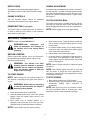
Figure 6
GEAR SELECTION HANDLE
The gear selection handle is located in the center of
the handle on the tiller. It is used to select NEUTRAL,
REVERSE, or one of the FORWARD modes (see
below). Pull or push the handle so that the indicator on
top of shift cover points to the operating mode desired.
See Figure 6.
NEUTRAL—Transmission is in neutral.
REVERSE—Reverse wheel drive.
FORWARD Modes:
Wheels Forward— Forward wheel drive only.
Tines Reverse— Forward wheel drive and reverse
tine drive.
Tines Forward— Forward wheel and tine drive.
IMPORTANT: Use the reverse tine drive when
tilling virgin ground, sod, or hard soil. Use the forward
tine drive when cultivating or tilling soft ground.
NOTE: If difficulty is encountered in moving the gear
selection handle, move the tiller forward or backward
slightly to allow the gears to synchronize.
• To shift into forward or reverse wheel drive,
move tiller forward slightly then backward to
allow the gears to synchronize.
• To shift into forward wheels and tine drive, push
forward slightly on the gear selection handle and
slowly engage the clutch control allowing the
gears to synchronize.
• To stop forward movement and tine drive,
release the clutch control. Do not shift gears
with the clutch control engaged except when
engaging the tines.
WARNING: Make certain unit is in
NEUTRAL when starting the engine.
Height
Adjustment
Lever
Control
Rod
Gear
Selection
Handle
Clutch
Control
Bail
Clutch
Cable
Cable Tie

9
DEPTH STAKE
The depth bar controls the tilling depth. Refer to
SECTION 6: HOW TO USE YOUR TILLER on page
10.
ENGINE CONTROLS
See the separate engine manual for additional
information and functions of the engine controls.
PRIMER BUTTON (if equipped)
The primer button is located behind the air cleaner. It
is used to enrich the fuel mixture in the carburetor
when starting a cold engine.
HANDLE ADJUSTMENT
The handle may be adjusted to be raised or lowered in
line with the tiller. To adjust the handle position loosen
the handle height adjustment crank a few turns. Pivot
handle up or down to desired position. Tighten crank.
See Figure 6.
CLUTCH CONTROL BAIL
The clutch control bail is located below the handle.
See Figure 6. Lifting the clutch control bail against the
handle engages the wheel and tine drive mechanisms.
NOTE: Never engage clutch lever while shifting.
SECTION 5: OPERATION
NOTE: Engine is shipped WITHOUT oil.
WARNING: Read, understand, and
follow all instructions and warnings on
the machine and in this manual before
operating.
BEFORE STARTING
Service engine with gasoline and oil as instructed in
the separate engine manual packed with your tiller.
Read instructions carefully.
WARNING: Use extreme care when
handling gasoline. Gasoline is extremely
flammable and the vapors are explosive.
Never fuel machine indoors or while the
engine is hot or running.
TO START ENGINE
NOTE: When pushing the unit with the engine off,
you will hear a ratcheting sound (gear noise) which is
normal.
WARNING: Be Sure No One Is Standing
In Front Of The Tiller While The Engine Is
Running Or Being Started.
1. Place gear selection lever in NEUTRAL.
2. Place the throttle control lever in the FAST (rabbit)
position. Place the engine speed control in the
START position.
3. Move choke lever to CHOKE position or if
equipped, push primer two (2) or three (3) times.
Wait about two (2) seconds between each push.
NOTE: A warm engine may not require choking.
4. Stand at side of tiller. Grasp the starter handle and
pull out slowly, until it pulls slightly harder. Let rope
rewind slowly.
5. Pull starter handle rapidly. Do not allow handle to
snap back. Allow it to rewind slowly while keeping
a firm hold on the starter handle.
6. Repeat steps 3 and 4 until engine starts.
7. As engine warms up and begins to operate evenly,
move choke lever gradually to RUN position. If
engine falters, return to choke position, then slowly
move to RUN position.
NOTE: Refer to engine manual for additional engine
information.
NOTE: After starting engine and prior to using the
tiller, be certain to check the clutch adjustment as
described in “Checking the Clutch Adjustment” section
of Assembly Instructions.
TO STOP ENGINE
1. Move throttle control to the STOP position.
2. Disconnect spark plug wire and ground to prevent
accidentally starting while equipment is
unattended.
NOTE: After the first ten hours of operation, recheck
the clutch adjustment. Refer to “Checking the Clutch
Adjustment” section of the Assembly Instructions.

10
SECTION 6: HOW TO USE YOUR TILLER
WARNING: Be certain the spark plug
wire is disconnected and grounded
against the engine when performing any
adjustments.
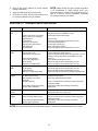
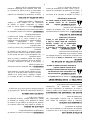
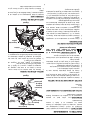
Tilling depth is controlled by the depth stake which can
be adjusted to five different settings. See Figure 7.
Adjust the side shields as shown in Figure 7, as you
adjust the depth stake. Be certain spark plug wire is
disconnected and grounded against the engine.
1. When using the tiller for the first time, use the
second adjustment hole from the top (1" of tilling
depth). See Figure 7.
2. When breaking up sod and for shallow cultivation,
use the setting which gives 1" of tilling depth
(second hole from the top). Place the side shields
in their lowest position. For further depth, raise the
depth stake and side shields and make one or two
more passes over the area.
3. When tilling loose soil, depth stake may be raised
to its highest position (use bottom adjustment
hole) to give the deepest tilling depth. Raise the
side shields to their highest position.
4. To transport tiller, lower the depth stake (use top
adjustment hole).
To adjust the depth stake, remove the clevis pin and
hairpin clip. See Figure 7. Move the depth stake to the
desired setting and secure with the clevis pin and
hairpin clip.
To adjust the side shields, remove the wing nuts. See
Figure 7. Place side shield in position desired. Replace
wing nuts and tighten securely.
TO OPERATE THE TILLER:
1. Select the depth stake setting.
2. Start engine as instructed on page 9.
3. Move gear selection handle to one of the forward
modes or reverse.
WARNING: Do not move the gear
selection handle with the wheels or tines
engaged. Make certain the unit is stopped
completely before changing the gear
selection.
IMPORTANT: Use the reverse tine drive when
tilling virgin ground, sod or hard soil. Use the forward
tine drive when cultivating or tilling soft ground.
4. Squeeze the clutch control bail against the handle
to engage the wheels and tines.
NOTE: Make certain the gear selection indicator is
correctly positioned before engaging the clutch handle.
If it is between gears, the engine will stall.
Figure 7
To transport tiller, do not engage the tines. Select the
wheel drive only.
WARNING: Do not push down on the
handles so that the wheels are lifted off
the ground while using the reverse tine
drive, or the tiller could move backward
and cause personal injury.
For best results, it is recommended the garden be tilled
twice (lengthwise, then widthwise) to pulverize the soil.
Use This
Position
First Time
Transport Position
1”
3”
5”
7”
Clevis Pin
Use This Hole For
Lowest (shallowest)
Position
Use This Hole For
Highest (Deepest)
Position
Side Shields

11
SECTION 7: ADJUSTMENTS
WARNING: Never attempt to make any
adjustments while the engine is running,
except where specified in operator’s
manual.
HANDLE ADJUSTMENT
The handle height may be adjusted. Refer to the
Control section for details of handle adjustment.
BELT TENSION ADJUSTMENT
Periodic adjustment of the belt tension may be
required due to normal stretch and wear on the belt.
Adjustment is needed if the tines or wheels seem to
hesitate while turning, but the engine maintains the
same speed.
To adjust the tension on the belt, refer to clutch
adjustment information in “Checking the Clutch
Adjustment” section of the Assembly Instructions.
After belt tension has been adjusted, if the belt is
excessively stretched, you may need to adjust the idler
pulley rod. This can easily be checked.
With the engine off and the clutch control bail
disengaged, shift the gear selection handle to each
forward mode. If the indicator bracket touches the idler
pulley rod, (with the clutch control bail disengaged),
then an adjustment is necessary.
1. Disconnect and ground out spark plug wire against
the engine.
2. Remove the belt cover as described in the belt
replacement section on page 12.
3. Remove the hairpin clip and flat washer from the
idler pulley rod. See Figure 9.
4. Move the idler pulley rod to the lower hole in the
idler bracket. See Figure 9.
5. Replace the wave washer and hairpin clip.
6. Check clearance of the idler pulley rod to the
indicator bracket by shifting to each forward mode,
as before.
CARBURETOR ADJUSTMENT
WARNING: If any adjustments are made
to the engine while the engine is running,
(e.g. carburetor), disengage all clutches
and tines. Keep clear of all moving parts.
Be careful of heated surfaces and muffler.
Never make unnecessary adjustments. The factory
settings are correct for most applications. If
adjustments are needed, refer to the separate engine
manual packed with your tiller.
SECTION 8: LUBRICATION
Transmission—The transmission is pre-lubricated
and sealed at the factory. It requires no checking
unless the transmission is disassembled. To fill with
grease, lay the right half of the transmission on its
side. Add 30 ounces of Benalene 920 grease. Apply a
bead of RTV or silicone sealant to the right half of the
transmission, all the way around the gear
compartment. Assemble the left half to it. This grease
can be obtained at your nearest authorized dealer.
Order part number 737-0300.
Clutch Bail—Lubricate the pivot point on the clutch
bail and the cable at least once a season with light oil.
The control must operate freely in both directions.
Pivot Points—Lubricate all pivot points and linkages
at least once a season with light oil.
Tine Shaft—Remove tines at least once a season and
lubricate with oil.
Wheel Axle—Remove the wheel assemblies at least
once a season and lubricate with oil.
SECTION 9: MAINTENANCE
WARNING: Disconnect the spark plug
wire and ground it against the engine
before performing any repairs or
maintenance.
ENGINE
Refer to the separate engine manual for engine
maintenance instructions.
Maintain engine oil as instructed in the separate
engine manual packed with your unit. Read and follow
instructions carefully.
Service air cleaner every ten hours under normal
conditions. Clean every hour under extremely dusty
conditions. Poor engine performance and flooding
usually indicates that the air cleaner should be
serviced. To service the air cleaner, refer to the
separate engine manual packed with your unit.
IMPORTANT: Never run your engine without air
cleaner completely assembled.

12
The spark plug should be cleaned and the gap reset
every 25 hours of engine operation. Spark plug
replacement is recommended at the start of each tiller
season; check engine manual for correct plug type and
gap specification.
Clean the engine regularly with a cloth or brush. Keep
the cooling system (blower housing area) clean to
permit proper air circulation which is essential to
engine performance and life. Be certain to remove all
dirt and combustible debris from muffler area.
CLEANING THE TINE AREA
Clean the underside of the tine shield after each use.
The dirt washes off the tines easier if washed off
immediately instead of after it dries. Always towel dry
the tiller afterwards and apply a light coat of oil or
silicone to prevent rusting or water damage.
IMPORTANT: Never use a "pressure washer" to
clean your tiller. Water can penetrate tight areas of the
tiller and its chain case and cause serious damage to
the unit.
BELT REPLACEMENT
Your tiller has been engineered with a belt made of
special material (Kevlar Tensile) for longer life and
better performance. It should not be replaced with an
off-the-shelf belt.
If belt replacement is required, order belt or belts by
part number from your nearest authorized dealer.
Part No. 754-0434—‘‘V’’ Belt
1. Disconnect and ground the spark plug wire against
the engine.
2. Remove the belt cover from the left side of the
tiller as follows: See Figure 8. Remove two torx
screws from the top of belt cover.
3. Remove the hex cap nut and flat washer from the
side of the belt cover. Remove the hex screw at the
bottom of the front of the cover.
4. Remove the belt keeper bracket located behind
the engine pulley by removing two hex bolts and
lock washers. See Figure 9.
5. Remove belt. Reassemble new belt, following
instructions in reverse order.
NOTE: Upon reassembly, make certain the belt is
routed over the idler pulley and inside of belt keepers
by engine pulley. See Figure 9.
Figure 8
Figure 9
TIRES
Recommended operating tire pressure is
approximately 20 p.s.i. (check sidewall of tire for tire
manufacturer’s recommended pressure). Maximum
tire pressure under any circumstances is 30 p.s.i.
Equal tire pressure should be maintained on both tires.
When installing a tire to the rim, be certain rim is clean
and free of rust. Lubricate both the tire and rim
generously. Never inflate to over 30 p.s.i. to seat
beads.
WARNING: Excessive pressure (over 30
p.s.i.) when seating beads may cause tire/
rim assembly to burst with force sufficient
to cause serious injury.
SECTION 10: OFF-SEASON STORAGE
If the tiller will not be used for a period longer than 30
days, the following steps should be taken to prepare
the tiller for storage.
1. Clean the exterior of engine and the entire tiller
thoroughly. Lubricate the tiller as described in the
lubrication instructions.
2. We do NOT recommend the use of pressure
washers to clean your unit. They may cause
damage to electric components, spindles, pulleys,
bearings or the engine. The use of pressure
washers will result in shortened life and reduced
serviceability.
Torx Screws
Belt Cover
Hex Cap Nut
Self Tap
Screw
Engine
Pulley
Belt Keeper
Idler
Brkt.
Idler
Pulley
Rod
Brkt.

13
3. Refer to the engine manual for correct engine
storage instructions.
4. Wipe tines with oiled rag to prevent rust.
5. Store tiller in a clean, dry area. Do not store next
to corrosive materials, such as fertilizer.
NOTE: When storing any type of power equipment
in an unventilated or metal storage shed, care
should be taken to rustproof the equipment. Using a
light oil or silicone, coat the equipment, especially
any springs, bearings and cables.
SECTION 11: TROUBLE SHOOTING GUIDE
NOTE: For repairs beyond the minor adjustments above, contact your local authorized service dealer.
Trouble Possible Cause(s) Corrective Action
Engine fails to
start
Fuel tank empty, or stale fuel.
Throttle control lever not in correct
starting position (if so equipped).
Blocked fuel line.
Dirty aircleaner.
Choke not in ON position.
Spark plug wire disconnected.
Faulty spark plug.
Engine flooded.
Fill tank with clean, fresh gasoline. Fuel will not last over
thirty days unless a fuel stabilizer is used.
Move throttle lever to start position.
Clean fuel line.
Refer to the engine manual packed with your unit.
Move switch to ON position.
Connect wire to spark plug.
Clean, adjust gap or replace.
Refer to the engine manual packed with your unit.
Engine runs
erratic
Unit running on CHOKE.
Spark plug wire loose.
Blocked fuel line or stale fuel.
Vent in gas cap plugged.
Water or dirt in fuel system.
Dirty air cleaner.
Carburetor out of adjustment.
Move choke lever to OFF position.
Connect and tighten spark plug wire.
Clean fuel line; fill tank with clean, fresh gasoline. Fuel will
not last over thirty days unless a fuel stabilizer is used.
Clear vent.
Drain fuel tank. Refill with fresh fuel.
Refer to the engine manual packed with your unit.
Refer to the engine manual packed with your unit.
Engine over-
heats
Engine oil level low.
Dirty air cleaner.
Air flow restricted.
Carburetor not adjusted properly.
Fill crankcase with proper oil.
Refer to the engine manual packed with your unit.
Refer to the engine manual packed with your unit.
Adjust carburetor as instructed in separate engine manual.
Tines do not
engage
Foreign object lodged in tines.
Tine clevis pin(s) missing.
Pulley and idler not in correct
adjustment.
Not shifting properly.
Control cable not adjusted properly.
Belt worn and/or stretched.
Dislodge foreign object.
Replace tine clevis pin(s).
Take unit to authorized service dealer.
Refer to Controls section of operator’s manual for proper
shifting procedures.
Adjust control cable (see assembly instructions).
Replace belt.
Tines skip over
ground
Improper rotation. Forward rotation should only be used on soil that has
already been tilled, not on virgin soil.
Wheels do not
engage
Clevis pin missing.
Tiller is not being shifted properly.
Control cable not adjusted properly.
Belt worn and/or stretched.
Replace clevis pin.
Refer to Controls section of operator’s manual for proper
shifting procedures.
Adjust control cable (see assembly instructions).
Replace belt.

14
52
13
29
55
16
53
55
16
46
31
28
12
45
17
17
44
36
6
3
33
15
27
5
36
43
4
20
40
21
1
34
18
10
42
23
7
22
36
8
47
32
37
50
25
10
9
24
36
51
34
45
26
41
36
55
16
29
19
49
44
33
14
55
16
2
14
28
35
16
14
11
48
14
54

15
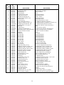
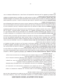
REF.
NO.
N°. DE
RÉF.
PART
NO.
N° DE
PIÈCE DESCRIPTION DESCRIPTION
1 611-0020 Wheel Shaft Ass'y 33T Arbre de roue 33 dents
2 611-0021 Tine Shaft Ass'y 18T Arbre de dents - 18 dents
3 611-0128 Jack Shaft Ass'y Arbre secondaire
4 611-0129 Input Shaft Ass'y Arbre
5 617-0058 Rev. Idler Gear Ass'y 30T Engrenage 30 dents
6 617-0059 Fr. Idler Gear Ass'y 30 T Engrenage 30 dents
7 617-0060 Tine Input Sprocket Ass'y 9T Pignon - 9 dents
8 617-0061 Wheel Input Sprocket Ass'y 10T Engrenage 10 dents
9 617-0062 Gear Ass'y 11T Engrenage 11 dents
10 686-0108 RH Housing Ass'y Boîtier de transmission - droite
11 710-0376 Hex. Scr 5/16-18 x 1.00 Gr. 5 Vis à tête hex. 5/16-18 x 1,00 Qual. 5
12 710-0599 Hex Wash S-Tapp Scr 1/4-20 x .50 Vis autotaraudeuse à rondelle hex. de 1/4-20 x 0,5
13 710-0604A Self-tapping Screw 5/16-18 x .625 Vis autotaraudeuse 5/16-18 x 0,625 po
14 710-3008 Hex Bolt 5/16-18 x .75" Lg. Gr. 5 Boulon hex. 5/16-18 x 0,75 po de lg. Qual. 5
15 711-1349 Input Shaft Arbre
16 712-0378 Hex Nut 7/16-20 Écrou à six pans 7/16-20
17 712-3004A Hex Flange L-Nut 5/16-18 Gr. 5 Contre-écrou de collet hex. 5/16-18 Qual. 5
18 713-0367 #420 Chain 1/2 Pitch x 50 Links-Endless Chaîne, no 420 pas de 1/2 x 50 maillons
19 713-0484 #50 Chain 5/8 Pitch x 54 Links Chaîne no 50, 5/8 x 54 maillons
20 716-0865 Snap Ring Joint
21 717-0853 Shifting Fork Fourchette
22 717-1582 Spur Gear 44T Engrenage 44 dents
23 717-1583 Spur Gear 30T Engrenage 30 dents
24 717-1584 Spur Gear 30T Engrenage 30 dents
25 717-1585 Spur Gear 44T Engrenage 44 dents
26 717-1587 Spur Gear 44T Engrenage 44 dents
27 717-1594 Spur Gear 16T Engrenage 16 dents
28 721-0378 Seal 1.0" Shaft Joint de 1,0 diam. arbre
29 721-0379 Seal .75 Shaft Joint de 0,75 diam. arbre
31 726-0277 Taper Cap Plug Bouchon à capuchon effilé
32 732-0496 Compression Spring .50" Lg. Ressort de compression 0,50 po de lg
33 736-0163 Flat Washer 1.03 ID x 1.62 OD x .03 Rondelle plate 1,03 DI x 1,62 DE x 0,03
34 736-0351 Flat Washer .76 ID x 1.5 OD x .03 Rondelle plate 0,76 DI x 1,5 DE x 0,03
35 736-0226 Flat Washer .469 ID x .88 OD x .063 Rondelle plate 0,469 DI x 0,88 DE x 0,063
36 736-0518 Thrust Wash. .445 ID x 1.92 OD Rondelle de butée 0,445 DI x 1,92 DE
37 736-3088 Flat Washer .635" ID x 1.59 OD Rondelle plate 0,635 DI x 1,59 DE
40 738-0645 Detent Shaft 1/2" Dia. Arbre à cliquet de 1/2 po de diamètre
41 738-0648 Jack Shaft 5/8" Dia. x 2.38 Arbre secondaire 5/8" diam. x 2,38
42 738-1013 Jack Shaft .625 x 5.0 Arbre secondaire 0,625 x 5,0
43 741-0124 Ball Bearing Roulement à billes
44 741-0420 Tine Shaft Brg. 1.002 x 2.50 Roulement de l'arbre des dents - 1,002 x 2,50
45 741-0421 Wheel Brg. .752" x 2.5” Roulement 0,752 po x 2,50 po
46 741-0563 Ball Bearing w/snap ring Roulement à billes avec bague
47 741-0862 Ball Detent .250 DIA Bille de verrouillage 0,250 dia.
48 750-0258 Spacer .315" ID x .375" Lg. Entretoise 0,315 DI x 0,375 po de lg.
49 750-0570 Step Spacer Cale d'espacement
50 750-0664 Spacer .505 ID x .88 OD Entretoise 0,505 DI x 0,88 DE
51 750-0671 Spacer .75" ID x .50" Lg. Entretoise 0,75 DI x 0,50 po de lg
52 786-0171 LH Chain Case Ass'y Ensemble de carter de chaîne de gauche
53 786-0238 Gear Positioner Bracket Support
54 736-0171 Lockwasher 7/16 ID Rondelle frein 7/16 DI
55 736-0407 Cupped Washer, .45 x 1.0 x .062 Rondelle creuse 0,45 x 1,0 x 0,062 po
686-0107 Gear Case Ass'y Complete Ensemble de carter de l'engrenage complet
214-450
11.28.03

16
20
18
8
23
10
1
60
61
37
62
25
34
27
64
30
39
63
26
32
36
33
31
29
66
26
41
30
30
24
28
35
40
26
49
6
59
51
65
53
55
56
54
57
58
44
46
42
4
9
11
16
6
3
14
7
19
5
17
2
60
61
12
15
12
38
21
22
67
70
70
68
69
27
50

17
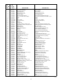
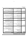
REF.
NO.
N°. DE
RÉF.
PART
NO.
N° DE
PIÈCE DESCRIPTION DESCRIPTION
1 747-1152 Shift Rod Tige de changement de vitesses
2 649-0041 Upper Handle Assembly Guidon supérieur
3 649-0034 Lower Handle Ass'y Guidon inférieur
4 710-3005 Hex Bolt 3/8-16 x 1.25 Boulon hex. 3/8-16 x 1,25
5 710-3056 Hex Bolt 5/16-18 x 3.25 Boulon hex. 5/16-18 x 3,25
6 711-0415 Clevis Pin 3/8 Dia Axe de chape 3/8 Dia.
7 712-0379 Hex Flange Nut 3/8-24 Thd. Écrou à six pans à collet de 3/8 - fil. 24
8 712-0429 Hex Ins. L-Nut 5/16-18 Gr. 5 Nylon Contre-écrou de blocage 5/16-18 Qual. 5 nylon
9 714-0147 Hairpin Goupille
10 720-0313 Grip Poignée
11 720-0210A Small "T" Knob Bouton en <<T>> (Petite)
12 720-0278A Foam Grip (2 req'd) Poignée de mousse (qté. 2)
14 726-0317 Cable Tie Attache câble
15 735-0246 Vinyl End Plug Bouchon - vinyl
16 736-0117 Flat Washer .385 ID x .62 OD x .033 Rondelle plate 0,385 DI x 0,62 DE x 0,033
17 736-0242 Cupped Washer .340 ID x .872 OD x .060 Rondelle creuse 0,340 DI x 0,872 DE x 0,060
18 738-0958 Shoulder Spacer Cale d'épaulement
19 784-0190 Handle Adj. Crank Manivelle de réglage du guidon
20 784-0191 Bracket Hex Nut Retainer Support de retenue à écrou à six pans
21 786-0120 Depth Bar Barre de profondeur d'attelage
22 747-1219 Clutch Bail Barre de commande de l'embrayage
23 786-0181 Shift Lever Rod Tige de levier de changement de vitesses
24 686-0044A Tine Shield Cover Ass'y Couvercle
25 710-0176 Hex Scr 5/16-18 x 2.75 Vis à tête hexagonale 5/16 x 2,75
26 710-3008 Hex Bolt 5/16-18 x .75" Lg. Gr. 5 Boulon hex. 5/16-18 x 0,75 po de lg. qual. 5
27 710-3097 Carriage Bolt 3/8-16 x 1.0" Lg. Boulon ordinaire 3/8-16 x 1,0 po de lg
28 712-0421 Wing Nut Écrou à oreilles
29 736-0169 L-Wash 3/8 ID Rondelle frein 3/8 DI
30 712-3004A Hex Flange L-Nut 5/16-18 Gr. 5 Contre-écrou de collet hex. 5/16-18 Qual. 5
31 726-0106 Push Cap Coiffe
32 738-0849 Hex Screw 5/16-18 x .75 Vis à tête hex. 5/16-18 x 0,75
33 747-0432 Tiller Flap Rod Tige de protecteur de dents
34 750-0885A Spacer .322 ID x .625 OD Entretoise 0,322 DI x 0,625 DE
35 786-0090 Side Shield Dispositif de protection latéral
36 786-0113 Rear Tine Shield Protecteur de dents
37 786-0176 RH Handle Brkt. Support du guidon - droite
38 786-0177 LH Handle Brkt. Support du guidon - gauche
39 786-0178 Tine Shield Bouclieur de dents
40 786-0179 Tine Shield Brkt. Support de bouclier de dents
41 786-0180 Shoulder Spacer Brkt. Support
42 686-0109 Shift Crank Ass'y Manivelle de changement de la vitesse
44 710-1017 Torx Mach. AB-Tapp Scr. 1/4 x .62" Lg. Vis torx AB 1/4 x 0,62 po de lg
46 715-0120 Spring Pin Roll 3/16 Dia. Goupille ronde à ressort de 5/16
49 784-0208C Shift Cover Couvercle
50 784-0160 Tine Adapter Ass'y 18” Adaptateur des dents 18 po
51 712-3054 Hex L-Nut 3/8-24 (Grade 5) Écrou de blocage 3/8-24 (qual. 5)
53 742-0305 13" Dia. Articulating Tine Dent d'articulation de 13 po de diamètre
54 738-0689 Shld. Scr. 1/2 Dia. x .175 Vis à épaulement 1/2 x 0,175
55 736-0208 Flat Washer .51 ID x 1.50 OD x .075 Rondelle plate 0,51 DI x 1,50 DE x 0,075
56 736-0253 Cupped Washer .505 ID x 1.00 OD x .075 Rondelle creuse 0,505 DI x 1,00 DE x 0,075
57 738-0688 Shld. Bolt 1/2" Dia. x .320 Boulon épaulée 1/2 diam. x 0,320
58 784-0205 Tine Ass'y Comp. 18” Ensemble des dents 18 po
59 714-0149B Internal Cotter Pin Goupille fendue interne
60 735-0127 Rubber Washer Rondelle en caoutchouc
61 714-0104 Int. Cotter Pin 5/16 Dia. Goupille fendue 5/16 dia.
62 710-3022 Hex Screw 3/8-16 x 2.75" Lg. Vis à tête hex 3/8-16 x 2,75 po de lg.
63 736-0204 Flat Washer .34 ID x .62 OD x .03 Rondelle plate 0,34 DI x 0,62 DE x 0,03
64 712-0431 Flanged Lock Nut 3/8-16 Gr. F Contre-écrou de collet hex. 3/8-16 Qual. F
65 736-0169 L-Wash 3/8 ID Rondelle frein 3/8 DI
66 712-3017 Hex Nut 3/8-16 Gr. 5 Écrou hex. 3/8-16 Qual. 5
67 710-0946 Truss Mach. Scr. 1/4-20 x .62" LG. Vis taraudée 1/4-20 x 0,62 po de lg
68 712-0324 Hex Ins. Locknut 1/4-20 Gr. 8 Nylon Écrou de blocage 1/4-20 Qual. 8 nylon
69 726-0273 Battery Hose Clamp Collier
70 736-3090 Flat Washer .260 x .72 x .060 Rondelle plate 0,260 x 0,72 x 0,060
214-4501
10.12.04

18
18
17
24
19
27
45
44
12
26
45
6
1
8
25
14
28
20
2
11
4
22
23
16
5
21
7
13
15
3
40
43
42
41
39
32
10
31
30
29
36
34
37
38
35
10
33

19
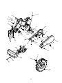
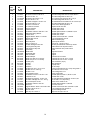
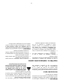
REF.
NO.
N°. DE
RÉF.
PART
NO.
N° DE
PIÈCE DESCRIPTION DESCRIPTION
1 686-0111 Belt Cover Brkt Ass'y Support de couvercle de la courroie
2 710-0237 Hex Screw 5/16-24 x .625 Gr. 5 Vis à tête hexagonale 5/16-24 x 0,625 Qual. 5
3 710-0412 Hex Scr 1/4-28 x .75 Vis à tête hexagonale 1/4-28 x 0,75
4 710-0502A Hex Washer Scr 3/8-16 x 1.25 Vis à chapeau à six pans 3/8-16 x 1,25 po
5 710-0152 Hex Scr 3/8-24 x 1.00 Vis à tête hexagonale 3/8-24 x 1,00
6 710-0599 Hex Wash S-Tapp Scr 1/4-20 x .50 Vis autotaraudeuse à rondelle hex. de 1/4-20 x 0,5
7 710-0723 Hex Screw 3/8-16 x 1.25 Vis à tête hexagonale 3/8-16 x 1,25
8 712-0266 Hex Cent L-Nut 3/8-16 Contre-écrou de blocage 3/8-16
10 714-0104 Int. Cotter Pin 5/16 Dia. Goupille fendue 5/16 dia.
11 736-0104 Internal L-Washer Rondelle frein interne
12 736-0119 L-Wash 5/16 ID Rondelle frein 5/16 DI
13 736-0176 Flat Washer .265 ID x .938 OD x .120 Rondelle plate 0,265 DI x 0,938 DE x 0,120
14 736-0271 Shakeproof Spring Washer Rondelle anti-vibration
15 736-0329 L-Wash 1/4 ID Rondelle frein 1/4 DI
16 736-0452 Cupped Washer .396 ID x 1.140 OD Rondelle creuse 0,396 DI x 1,140 DE
17 738-0876 Shoulder Nut 7/16-20 Écrou à épaulement 7/16-20
18 746-1117 Clutch Cable Câble de l'embrayage
19 747-1159 Idler Pulley Rod Tige de poulie tendeur
20 754-0434 Belt: 4L x 58.16" Lg. Courroie: 4L x 58,16 po de lg.
21 756-0405 Flat Idler w/flanges 3-3/4" OD Tendeur plat à brides de 3-3/4 de po de DE
22 756-0971 Inner Engine Pulley Half Moitié intérieure de la poulie motrice
23 756-0972 Outer Engine Pulley Half Moitié extérieure de la poulie motrice
24 756-1162 Input Pulley Poulie
25 786-0064A Idler Bracket Support de tendeur
26 785-0186 Belt Keeper Brkt. Support
27 786-0187 Shift Cover Brkt. Support
28 786-0193 Idler Belt Keeper Protecteur de la courroie
29 634-0238 Wheel Ass'y RH 16 x 4 x 8 Gray Ensemble de roue CD 16 x 4 x 8 gris
634-0239 Wheel Ass'y LH 16 x 4 x 8 Gray Ensemble de roue CG 16 x 4 x 8 gris
734-0808 Tire Only (16") Pneu seulement (16 po.)
30 634-0108 Rim Only Jante seulement
31 734-0255 Air Valve Soupape à air
32 711-1017 Clevis Pin Axe de chape
33 710-0805 Hex Bolt 5/16-18 x 1.50" Lg. Gr. 5 Boulon hexagonal 5/16-18 x 1,50 po de lg Qual. 5
34 710-0382 Hex Bolt 1/2-13 x 5.00" Lg. Vis à tête hex. 1/2-13 x 5,00
35 712-0206 Hex Nut 1/2-13 Écrou hexagonal 1/2-13
36 723-0381 Counterweight 40 Lbs. Contre poids 40 lbs.
37 736-0326 Flat Washer .510 ID x 1.00 OD x .125 Rondelle plate 0,510 DI x 1,00 DE x 0,125
38 736-0921 L-Washer 1/2" ID Rondelle frein 1/2 DI
39 710-0653 Hex Wash HD Tapp Scr 1/4-20 x .38 Vis auto-taraudeuse hexagonale 1/4-20 x 0,38
40 710-1017 Torx Mach. AB-Tapp Scr. 1/4 x .62" Lg. Vis torx AB 1/4 x 0,62 po de lg.
41 712-0392 Hex Lock Stop Nut 1/4-28 Contre-écrou d'arrêt 1/4-28
42 736-3020 Flat Washer .266 ID x .625 OD Rondelle plate 0,266 DI x 0,625 DE
43 784-0158A Belt Cover Couvercle courroie
44 736-0242 Cupped Washer .340 ID x .872 OD x .060 Rondelle creuse 0,340 DI x 0,872 DE x 0,060
45 712-3010 Hex Nut 5/16-18 hd. Gr. 5 Écrou hexagonal 5/16-18 Qual. 5
737-0298 Oil Drain Tube Tuyau de vidange d'huile
737-0132 Pipe Cap 1/4 x 18 N.P.T. Capuchon de tuyau 1/4 x 18
215-4502
10.22.04

20
TWO YEAR LIMITED WARRANTY
For TWO YEARS from the date of retail purchase within Canada, MTD PRODUCTS LIMITED will, at its option, re
-
pair or replace, for the original purchaser, free of charge, any part or parts found to be defective in material or
workmanship.
This warranty does not cover:
1. Any part which has become inoperative due to misuse, commercial use, abuse, neglect, accident, im
-
proper maintenance or alteration; or
2. The unit if it has not been operated and/or maintained in accordance with the owner’s instructions fur
-
nished with the unit; or
3. The engine or motor or component parts thereof which carry separate warranties from their manufac
-
turers. Please refer to The applicable manufacturer’s warranty on these items; or
4. Batteries and normal wear parts except as noted below. Log splitter pumps, valves and cylinders or
component parts thereof are covered by a one year warranty; or
5 Routine maintenance items such as lubricants, filters, blade sharpening and tune-ups, or adjustments
such as brake, clutch or deck; or
6. Normal deterioration of the exterior finish due to use or exposure.
Full Ninety Day Warranty on Battery: For ninety (90) days from the date of retail purchase, if any battery included
with this unit proves defective in material or workmanship and our testing determines the battery will not hold a
charge, MTD PRODUCTS LIMITED will replace the battery at no charge to the original purchaser.
Additional Limited Thirty Day Warranty on Battery: After ninety (90) days but within one hundred twenty (120)
days from the date of purchase, MTD PRODUCTS LIMITED will replace the defective battery, for the original pur-
chaser, for a cost of one-half (1/2) of the current retail price of the battery in effect at the date of return.
Full Sixty Day Warranty on Normal Wear Parts: Normal wear parts are defined as belts, blade adapters, blades,
grass bags, seats, tires, rider deck wheels and clutch parts (friction wheels). These parts are warranted to the origi-
nal purchaser to be free from defects in material and workmanship for a period of sixty (60) days from the date of
retail purchase.
How to Obtain Service: Warranty service is available, with proof of purchase, through your local authorized ser-
vice dealer or distributor. If you do not know the dealer or distributor in your area, please write to the Service
Department of MTD PRODUCTS LIMITED, P. O. BOX 1386, KITCHENER, Ontario, N2G 4J1. The return of a com
-
plete unit will not be accepted by the factory unless prior written permission has been extended by MTD
PRODUCTS LIMITED.
Transportation Charges: Transportation charges for the movement of any power equipment unit or attachment
are the responsibility of the purchaser. Transportation charges for any part submitted for replacement under this
warranty must be paid by the purchaser unless such return is requested in writing by MTD PRODUCTS LIMITED.
Other Warranties: All other warranties, express or implied, including any implied warranty of merchantability is lim
-
ited in its duration to that set forth in this express limited warranty. The provisions as set forth in this warranty
provide the sole and exclusive remedy of MTD PRODUCTS LIMITED obligations arising from the sale of its prod
-
ucts.
MTD PRODUCTS LIMITED will not be liable for incidental or consequential loss or damage.
La page est en cours de chargement...
La page est en cours de chargement...
La page est en cours de chargement...
La page est en cours de chargement...
La page est en cours de chargement...
La page est en cours de chargement...
La page est en cours de chargement...
La page est en cours de chargement...
La page est en cours de chargement...
La page est en cours de chargement...
La page est en cours de chargement...
La page est en cours de chargement...
La page est en cours de chargement...
La page est en cours de chargement...
La page est en cours de chargement...
La page est en cours de chargement...
-
 1
1
-
 2
2
-
 3
3
-
 4
4
-
 5
5
-
 6
6
-
 7
7
-
 8
8
-
 9
9
-
 10
10
-
 11
11
-
 12
12
-
 13
13
-
 14
14
-
 15
15
-
 16
16
-
 17
17
-
 18
18
-
 19
19
-
 20
20
-
 21
21
-
 22
22
-
 23
23
-
 24
24
-
 25
25
-
 26
26
-
 27
27
-
 28
28
-
 29
29
-
 30
30
-
 31
31
-
 32
32
-
 33
33
-
 34
34
-
 35
35
-
 36
36


MTD 450 Manuel utilisateur
- Catégorie
- Mini motoculteurs
- Taper
- Manuel utilisateur
- Ce manuel convient également à
dans d''autres langues
- English: MTD 450 User manual
Documents connexes
Autres documents
-
Troy-Bilt 21AB45M8B66 Manuel utilisateur
-
Cub Cadet 21AB455C710 Le manuel du propriétaire
-
Yard Machines Tiller 300 Manuel utilisateur
-
Poulan 96092001000 Manuel utilisateur
-
 Poulan Pro 96092002200 Manuel utilisateur
-
-
Poulan PRRT850X Manuel utilisateur
-
-
Jonsered J208D17 Manuel utilisateur
-
Ariens 90102800 Le manuel du propriétaire
