Mitsubishi Electric GT25 Open Frame Model Le manuel du propriétaire
- Taper
- Le manuel du propriétaire

GT25 Open Frame Model
General Description
Thank you for choosing Mitsubishi Electric Graphic Operation
Terminal (GOT).
© 2015MITSUBISHI ELECTRIC CORPORATION
GT2512F-STNA
GT2508F-VTNA
GT2512F-STND
GT2508F-VTND
GT2510F-VTNA GT2510F-VTND
Prior to use, please read both this manual and the
detailed manual thoroughly to fully understand the
product.
MODEL GT25F-U-GD-E
Model
code
1D7MQ5
IB(NA)-0800553ENG-F(2102)MEE
1
2
3
4
5
6
7
8
9
0
1
2
3
4
5
6
7
8
9
0
SAFETY PRECAUTIONS
(Always read these precautions before using this equipment.)
Before using this product, please read this manual and the relevant
manuals introduced in this manual carefully and pay full attention to
safety to handle the product correctly.
The precautions given in this manual are concerned with this prod-
uct.
In this manual, the safety precautions are ranked as "WARNING"
and "CAUTION".
Note that the CAUTION level may lead to a serious accident
according to the circumstances.
Always follow the instructions of both levels because they are import-
ant to personal safety.
Please save this manual to make it accessible when required and
always forward it to the end user.
[DESIGN PRECAUTIONS]
Indicates that incorrect handling may cause
hazardous conditions, resulting in death or
severe injury.
Indicates that incorrect handling may cause
hazardous conditions, resulting in medium or
slight personal injury or physical damage.
Some failures of the GOT, communication unit or cable may keep the outputs
on or off.
Some failures of a touch panel may cause malfunction of the input objects
such as a touch switch.
An external monitoring circuit should be provided to check for output signals
which may lead to a serious accident.
Not doing so can cause an accident due to false output or malfunction.
Do not use the GOT as the warning device that may cause a serious accident.
An independent and redundant hardware or mechanical interlock is required
to configure the device that displays and outputs serious warning.
Failure to observe this instruction may result in an accident due to incorrect
output or malfunction.
The GOT backlight failure disables the operation on the touch switch(s).
When the GOT backlight has a failure, the POWER LED blinks (orange/blue)
and the display section dims.
In such a case, the input by the touch switch(s) is disabled.
The display section of the GOT is an analog-resistive type touch panel.
Do not touch two points or more simultaneously on the display section.
Doing so may cause a touch switch near the touched points to operate
unexpectedly, or may cause an accident due to an incorrect output or
malfunction.
When programs or parameters of the controller (such as a PLC) that is
monitored by the GOT are changed, be sure to reset the GOT, or turn on the
unit again after shutting off the power as soon as possible.
Not doing so can cause an accident due to false output or malfunction.
If a communication fault (including cable disconnection) occurs during
monitoring on the GOT, communication between the GOT and PLC CPU is
suspended and the GOT becomes inoperative.
For bus connection: The PLC CPU becomes faulty and the GOT becomes
inoperative.
For other than bus connection: The GOT becomes inoperative.
A system where the GOT is used should be configured to perform any
significant operation to the system by using the switches of a device other
than the GOT on the assumption that a GOT communication fault will occur.
Not doing so can cause an accident due to false output or malfunction.
To maintain the security (confidentiality, integrity, and availability) of the GOT
and the system against unauthorized access, DoS
*1
attacks, computer
viruses, and other cyberattacks from unreliable networks and devices via
network, take appropriate measures such as firewalls, virtual private networks
(VPNs), and antivirus solutions.
Mitsubishi Electric shall have no responsibility or liability for any problems
involving GOT trouble and system trouble by unauthorized access, DoS
attacks, computer viruses, and other cyberattacks.
*1 DoS: A denial-of-service (DoS) attack disrupts services by overloading
systems or exploiting vulnerabilities, resulting in a denial-of-service (DoS)
state.
WARNING
CAUTION
WARNING
[MOUNTING PRECAUTIONS]
Products with the Cl.I, DIV.2 mark on the rating plate are suitable for use in
Class I, Division 2, Groups A, B, C and D hazardous locations, or
nonhazardous locations only.
This mark indicates that the product is certified for use in the Class I,
Division2 environment where flammable gases, vapors, or liquids are not
likely to exist under normal conditions.
When using the products in the Class I, Division 2 environment, observe the
following to reduce the risk of explosion.
• This device is open-type and is to be installed in an enclosure suitable for
the environment and require a tool or key to open.
• Warning - Explosion Hazard - Substitution of any component may impair
suitability for Class I, Division 2.
• Warning - Explosion Hazard - Do not connect or disconnect equipment or
disconnect external connection terminals unless power has been removed or
the area is known to be non-hazardous.
• The side interface and extension interface of this equipment cannot be used
in Class I, Division 2 environments.
Les produits marqués Cl.I, DIV.2 sur la plaque signalétique peuvent être
utilisés en Class I, Division 2, local dangereux de groupe A, B, C et D, ou
uniquement en local non dangereux.
Ce logo indique que le produit est homologué pour utilisation en
environnement de Class I, Division 2 où, dans des circonstances anormales,
il peut y avoir présence de gaz, vapeurs ou liquides inflammables.
Si le produit est utilisé en environnement de Class I, Division 2, observer les
précautions suivantes pour réduire le risque d'explosion.
• Cet appareil est de type ouvert et il doit être installé dans une enceinte
appropriée à l'environnement et ne pouvant être ouverte qu'au moyen
d'une clé ou d'un outil.
• Avertissement - Danger d'explosion - Toute substitution de composant
peut compromettre l'aptitude à l'utilisation en Class I, Division 2.
• Avertissement - Danger d'explosion - Ne pas connecter ou déconnecter
l'équipement ni déconnecter les bornes de connexion externes quand le
circuit est sous tension, ni avant de d'être assuré de l'absence d'atmosphère
inflammable.
• L'interface latérale et l'interface d'extension de cet équipement ne
peuvent être utilisées dans les environnements de Classe I, Division 2.
Do not bundle the control and communication cables with main-circuit, power
or other wiring.
Run the above cables separately from such wiring and keep them a minimum
of 100mm apart.
Not doing so noise can cause a malfunction.
Do not press the GOT display section with a pointed material as a pen or
driver.
Doing so can result in a damage or failure of the display section.
When the GOT connects to an Ethernet network, the IP address setting is
restricted according to the system configuration.
When a GOT2000 series model and a GOT1000 series model are on an
Ethernet network, do not set the IP address 192.168.0.18 for the GOTs and
the controllers on this network.
Doing so can cause IP address duplication at the GOT startup, adversely
affecting the communication of the device with the IP address 192.168.0.18.
The operation at the IP address duplication depends on the devices and the
system.
Turn on the controllers and the network devices to be ready for
communication before they communicate with the GOT.
Failure to do so can cause a communication error on the GOT.
When the GOT is subject to shock or vibration, or some colors appear on the
screen of the GOT, the screen of the GOT might flicker.
Be sure to shut off all phases of the external power supply used by the
system before mounting or removing the GOT main unit to/from the panel.
Not doing so can cause the unit to fail or malfunction.
Be sure to shut off all phases of the external power supply used by the
system before mounting or removing the communication unit or the option
unit onto/from the GOT.
Use the GOT in the environment that satisfies the general specifications
described in this manual.Not doing so can cause an electric shock, fire,
malfunction or product damage or deterioration.
When mounting a unit on the GOT, tighten the mounting screws in the
following specified torque range. When loading the communication unit or
option unit other than wireless LAN unit to the GOT, fit it to the connection
interface of the GOT and tighten the mounting screws in the specified torque
range (0.36 N•m to 0.48 N•m) with a Phillips-head screwdriver No.2.
When loading the wireless LAN unit to the GOT, fit it to the side interface of
GOT and tighten the mounting screws in the specified torque range (0.10
N•m to 0.14 N•m) with a Phillips-head screwdriver No.1.
When the GOT is installed vertically, its side interface is positioned on the
bottom.To prevent the falling of the wireless LAN communication unit from the
side interface, install or remove the unit while holding it with hands.
Under tightening can cause the GOT to drop, failure or malfunction.
Overtightening can cause a drop, failure or malfunction due to the damage of
the screws or unit.
Remove the protective film of the GOT.
When the user continues using the GOT with the protective film, the film may
not be removed.
Attach an environmental protection sheet dedicated to the open frame model
(sold separately) to the display section of GOT.
Or, attach a user-prepared environmental protection sheet.
Not doing so may damage or soil the GOT or cause foreign matter to enter
the GOT, resulting in a failure or malfunction.
When installing the supplied fittings, tighten screws in the specified torque
range (0.8 N•m to 1.0 N•m).
Meld studs on the control panel to fasten the fittings.
The studs must have strength adequate to withstand a tightening torque of
0.9 N•m or more.
Make sure that no foreign matter such as welding waste is at and around the
bases of the studs.
Tighten nuts on the studs in the specified torque range (0.8 N•m to 0.9 N•m)
with a wrench for M4 nuts.
Undertightening a screw or nut may cause the GOT to drop, short-circuit, or
malfunction.
Overtightening a screw or nut may damage it or the GOT, causing the GOT to
drop, short-circuit, or malfunction.
Do not operate or store the GOT in the environment exposed to direct
sunlight, high temperature, dust, humidity, or vibrations.
WARNING
CAUTION
WARNING
CAUTION
[WIRING PRECAUTIONS]
[TEST OPERATION PRECAUTIONS]
[STARTUP/MAINTENANCE PRECAUTIONS]
[TOUCH PANEL PRECAUTIONS]
Be sure to shut off all phases of the external power supply used by the
system before wiring.
Failure to do so may result in an electric shock, product damage or
malfunctions.
Make sure to ground the FG terminal and LG terminal of the GOT power
supply section solely for the GOT (ground resistance: 100 Ω or less, ground
cable diameter: 1.6 mm or more).
Not doing so may cause an electric shock or malfunction.
When tightening the terminal screws, use a Phillips-head screwdriver No.2.
Terminal screws which are not to be used must be tightened always at torque
0.5 N•m to 0.8 N•m.
Otherwise there will be a danger of short circuit against the solderless
terminals.
Use applicable solderless terminals and tighten them with the specified
torque. If any solderless spade terminal is used, it may be disconnected
when the terminal screw comes loose, resulting in failure.
Correctly wire the GOT power supply section after confirming the rated
voltage and terminal arrangement of the product.
Not doing so can cause a fire or failure.
Tighten the terminal screws of the GOT power supply section in the specified
torque range (0.5 N•m to 0.8 N•m). Undertightening can cause a short circuit
or malfunction.Overtightening can cause a short circuit or malfunction due to
the damage of the screws or the unit.
Exercise care to avoid foreign matter such as chips and wire offcuts entering
the GOT.
Not doing so can cause a fire, failure or malfunction.
The module has an ingress prevention label on its top to prevent foreign
matter, such as wire offcuts, from entering the module during wiring.
Do not peel this label during wiring.
Before starting system operation, be sure to peel this label because of heat
dissipation.
Plug the communication cable into the GOT interface or the connector of the
connected unit, and tighten the mounting screws and the terminal screws in
the specified torque range.
Undertightening can cause a short circuit or malfunction.
Overtightening can cause a short circuit or malfunction due to the damage of
the screws or unit.
Plug the QnA/ACPU/Motion controller (A series) bus connection cable by
inserting it into the connector of the connected unit until it "clicks".
After plugging, check that it has been inserted snugly.
Not doing so can cause a malfunction due to a contact fault.
Before testing the operation of a user-created monitor screen (such as
turning on or off a bit device, changing the current value of a word device,
changing the set value or current value of a timer or counter, and changing
the current value of a buffer memory), thoroughly read the manual to fully
understand the operating procedures.
During the test operation, never change the data of the devices which are
used to perform significant operation for the system.
False output or malfunction can cause an accident.
When power is on, do not touch the terminals.
Doing so can cause an electric shock.
Correctly connect the battery connector.
Do not charge, disassemble, heat, short-circuit, solder, or throw the battery
into the fire.
Doing so will cause the battery to produce heat, explode, or ignite, resulting in
injury and fire.
Before starting cleaning or terminal screw retightening, always switch off the
power externally in all phases. Not switching the power off in all phases can
cause a unit failure or malfunction.
Undertightening can cause a drop, short circuit or malfunction.
Overtightening can cause a drop, short circuit or malfunction due to the
damage of the screws or unit.
Do not disassemble or modify the unit.
Doing so can cause a failure, malfunction, injury or fire.
Do not touch the conductive and electronic parts of the unit directly.
Doing so can cause a unit malfunction or failure.
The cables connected to the unit must be run in ducts or clamped.
Not doing so can cause the unit or cable to be damaged due to the dangling,
motion or accidental pulling of the cables or can cause a malfunction due to a
cable connection fault.
When unplugging the cable connected to the unit, do not hold and pull from
the cable portion.
Doing so can cause the unit or cable to be damaged or can cause a
malfunction due to a cable connection fault.
Do not drop the module or subject it to strong shock. A module damage may
result.
Do not drop or give an impact to the battery mounted to the unit.
Doing so may damage the battery, causing the battery fluid to leak inside the
battery.
If the battery is dropped or given an impact, dispose of it without using.
Before touching the unit, always touch grounded metals, etc. to discharge
static electricity from human body, etc.
Not doing so can cause the unit to fail or malfunction.
Use the battery manufactured by Mitsubishi Electric Corporation.
Use of other batteries may cause a risk of fire or explosion.
Dispose of used battery promptly.
Keep away from children. Do not disassemble and do not dispose of in fire.
Be sure to shut off all phases of the external power supply before replacing
the battery or using the dip switch of the terminating resistor.
Not doing so can cause the unit to fail or malfunction by static electricity.
For the analog-resistive film type touch panels, normally the adjustment is not
required.
However, the difference between a touched position and the object position
may occur as the period of use elapses.
When any difference between a touched position and the object position
occurs, execute the touch panel calibration.
WARNING
CAUTION
WARNING
WARNING
CAUTION
CAUTION
[PRECAUTIONS WHEN THE DATA STORAGE IS IN USE]
[PRECAUTIONS FOR USE]
[PRECAUTIONS FOR REMOTE CONTROL]
[PRECAUTIONS FOR EXCLUSIVE AUTHORIZATION CONTROL]
[DISPOSAL PRECAUTIONS]
[TRANSPORTATION PRECAUTIONS]
When any difference between a touched position and the object position
occurs, other object may be activated.
This may cause an unexpected operation due to incorrect output or
malfunction.
If the SD card is removed from drive A of the GOT while being accessed by
the GOT, the GOT may stop processing data for about 20 seconds.
The GOT cannot be operated during this period.
The functions that run in the background including a screen updating, alarm,
logging, scripts, and others are also interrupted.
Since this interruption makes an impact to the system operation, it might
cause failure.
Check that the SD card access LED is off before removing the SD card.
If the data storage is removed from the GOT while being accessed by the
GOT, the data storage and files may be damaged.
Before removing the data storage from the GOT, check the SD card access
LED, system signal, or others to make sure that the data storage is not
accessed.
Turning off the GOT while it accesses the SD card results in damage to the
SD card and files.
After inserting an SD card into the GOT, make sure to close the SD card
cover. Not doing so causes the data not to be read or written.
When removing the SD card from the GOT, make sure to support the SD card
by hand as it may pop out.
Not doing so may cause the SD card to drop from the GOT, resulting in a
failure or break.
When inserting a USB device into a USB interface of the GOT, make sure to
insert the device into the interface firmly.
Not doing so can cause a malfunction due to a contact failure.
Before removing the data storage from the GOT, follow the procedure for
removal on the utility screen of the GOT.
After the successful completion dialog is displayed, remove the data storage
by hand carefully.
Not doing so may cause the data storage to drop from the GOT, resulting in a
failure or break.
Do not touch the outer edge of the actual display area repeatedly.
Doing so may result in a failure.
Do not turn off the GOT while data is being written to the storage memory
(ROM) or SD card.
Doing so may corrupt the data, rendering the GOT inoperative.
Remote control is available through a network by using GOT functions,
including the SoftGOT-GOT link function, the remote personal computer
operation function, the VNC server function, and the GOT Mobile function.
If these functions are used to perform remote control of control equipment,
the field operator may not notice the remote control, possibly leading to an
accident.
In addition, a communication delay or interruption may occur depending on
the network environment, and remote control of control equipment cannot be
performed normally in some cases.
Before using the above functions to perform remote control, fully grasp the
circumstances of the field site and ensure safety.
Make sure to fully understand the GOT network interaction function before
using this function to control the authorization among pieces of equipment to
prevent simultaneous operations.
The exclusive authorization control of the GOT network interaction function
can be enabled or disabled for each screen.
(For all screens, the exclusive authorization control is disabled by default.)
Properly determine the screens for which the exclusive authorization control
is required, and set the control by screen.
A screen for which the exclusive authorization control is disabled can be
operated simultaneously from pieces of equipment.
Make sure to determine the operation period for each operator, fully grasp the
circumstances of the field site, and ensure safety to perform operations.
When disposing of this product, treat it as industrial waste.
When disposing of batteries, separate them from other wastes according to
the local regulations.
(Refer to the GOT2000 Series User’s Manual (Hardware) for details of the
battery directive in the EU member states.)
When transporting lithium batteries, make sure to treat them based on the
transport regulations.
(Refer to the GOT2000 Series User’s Manual (Hardware) for details of the
regulated models.)
Make sure to transport the GOT main unit and/or relevant unit(s) in the
manner they will not be exposed to the impact exceeding the impact
resistance described in the general specifications of this manual, as they are
precision devices.
Failure to do so may cause the unit to fail.
Check if the unit operates correctly after transportation.
When fumigants that contain halogen materials such as fluorine, chlorine,
bromine, and iodine are used for disinfecting and protecting wooden
packaging from insects, they cause malfunction when entering our products.
Please take necessary precautions to ensure that remaining materials from
fumigant do not enter our products, or treat packaging with methods other
than fumigation (heat method).
Additionally, disinfect and protect wood from insects before packing products.
CAUTION
WARNING
CAUTION
CAUTION
WARNING
WARNING
CAUTION
CAUTION
Manuals
The following shows manuals relevant to this product.
For detailed manuals and relevant manuals, refer to the e-Manual or PDF
manuals stored in the DVD-ROM for the screen design software used.
The latest manuals are also available from MITSUBISHI ELECTRIC FA Global
Website (www.MitsubishiElectric.com/fa).
Compliance with the new China RoHS directive
GOT 相关的基于 “ 电器电子产品有害物质限制使用管理办法 ” 要求的表示方法
含有有害 6 物质的名称、含有量、含有部件
本产品中所含有的有害 6 物质的名称、含有量、含有部件如下表所示。
产品中有害物质的名称及含量
本表格依据 SJ/T11364 的规定编制。
○ : 表示该有害物质在该部件所有均质材料中的含量均在 GB/T26572 规定的限量要
求以下。
× : 表示该有害物质至少在该部件的某一均质材料中的含量超出 GB/T26572 规定的
限量要求。
Referenced Standard: GB/T15969.2
(Requirement of Chinese standardized law)
Before using the GOT
Connect the connector of the GOT to the connector of the battery.
Refer to the GOT2000 Series User’s Manual (Hardware) for the connection
instructions.
For details on the GOT specifications, installing instructions, wiring, maintenance
and inspection, or checking procedure for the version and the compatible standard,
refer to the GOT2000 Series User’s Manual (Hardware).
Packing List
The GOT product package includes the following:
To mount the GOT, studs are necessary on the control panel.
You are required to prepare the studs.
Align the studs with the installation holes of the fittings, and install the studs.
The control panel requires a thickness of 1.5 mm to 4 mm.
Attach the environmental protection sheet dedicated to the open frame model (sold
separately) to the GOT display section. Or, attach a user-prepared environmental
protection sheet. Not doing so may damage or soil the GOT or cause foreign
matter to enter the GOT, resulting in a failure or malfunction.
1. FEATURES
(1) Abundant standard equipment
• Variety of connection with FA devices
• SD card interface compatible with the SDHC card having a large capacity
and allowing high-speed communication
• Connection with various peripheral devices with the USB host
(2) Improved usability
• Abundant troubleshooting
• Easy and clear screen creation
• PC-like operation screen
• Support for the vertical installation
(3) Enhanced compatibility with Mitsubishi Electric FA devices
(4) LED backlight
(5) Various extended functions supported
(6) Improved usability
• The GOT front face and the control panel surface are in the same plane.
Manual name
Manual number
(Model code)
GOT2000 Series User’s Manual
(Hardware)
SH-081194ENG
(1D7MJ5)
GOT2000 Series User’s Manual (Utility)
SH-081195ENG
(1D7MJ6)
Note: This symbol mark is for China only.
部件名称
有害物质
铅
(Pb)
汞
(Hg)
镉
(Cd)
六价铬
(Cr(VI))
多溴联苯
(PBB)
多溴二苯醚
(PBDE)
电路板组件 × ○ ○ ○ ○ ○
树脂壳体、电缆、膜材 ○ ○ ○ ○ ○ ○
钣金部件、螺丝等金属部件 × ○ ○ ○ ○ ○
Description Quantity
GT25 1
Battery (GT11-50BAT) (Attached to the GOT) 1
Fitting (for fixing the GOT to the control panel)
2 (for fixing the top and
bottom of the GOT)
2 (for fixing the right and left
of the GOT)
Screw (for fixing the fitting to the GOT) 6
Nut (for fixing the fitting to the control panel) 6
GT25 Open Frame Model General Description (This
manual)
1
2. PARTS NAMES AND SETTINGS
The following shows the parts names for GT2512F-S, GT2510F-V and GT2508F-V.
No. Name Description
1) Display screen Displays the utility and the user-created screen.
2) Touch Pane
For operating the touch switches in the utility and the user-
created screen
3) Unit installation fitting Mounting fixtures for fixing the GOT to the control panel
4) Reset switch Hardware reset switch
5) Installation switch Used for OS installations at the GOT startup
6) SD card access LED
Lit: SD card mounted
Blinking: SC card accessed
No lit: SD card not mounted or SD card mounted
(removable)
7) SD card interface For installing a SD card
8) SD card cover
With a switching function for accepting and stopping the
access to the SD card
When the cover is opened : Access is prohibited
When the cover is closed : Access is allowed
9) Battery holder Houses the battery
10) POWER LED
Lit in blue : Power is properly supplied.
Lit in orange : Screen saving
Blinks in orange/blue : Backlight failure
Not lit : Power is not supplied
(You can check the LED status from the GOT rear face.)
11) Side interface For installing a communication unit
12)
USB interface
(Host/Back face)
For connecting a USB mouse, a USB keyboard, or a USB
barcode reader, and transferring or saving data (Connector
shape: TYPE-A)
13)
Hole for attaching a
cable clamp
Hole for attaching a cable clamp for preventing USB cable
from being pulled out
(Recommended product: SKB-132PWD of SK KOHKI CO.,
LTD. or corresponding product)
6)
7)
8)
22)
22)
10)
3)
11)
9)
20)
19)
21)
18)
17)
3)
22)
22) 22)
15)
4)
14)
5)
3)
22)
1)2)
16)
3)
22)
22)
22)
22)
GT2512F-S
12)
13)
6)
7)
8)
22)
22)
10)
3)
12)
13)
11)
9)
20)
19)
21)
18)
17)
3)
22)
22)
22)
15)
4)
14)
5)
3)
22)
1)2)
16)
3)
22)
22)
22)
22)
GT2510F-V
6)
7)8)9)
22)
22)
10)
3)
12)
11)
20)
19)
18)
17)
3)
22)22)
15)
4)
14)
5)
3) 22)
21)
1)2)
16)
3)
22)
22)
22)
GT2508F-V
The figure shows a GOT with the fittings
installed on the top, bottom, right, and left.
Install the fittings on the top and bottom,
or the right and left of the GOT.
3. SPECIFICATIONS
3.1 General Specifications
*1: The operating ambient temperature includes the temperature inside the
enclosure of the control panel to which the GOT is installed.
La température ambiante de fonctionnement inclut la température à l'intérieur
du boîtier du tableau de commande sur lequel le GOT est installé.
*2: When mounting a MELSECNET/H communication unit (GT15-J71LP23-25,
GT15-J71BR13), or CC-Link communication unit (GT15-J61BT13), the
operating ambient temperature must be reduced
5 against the maximum
values described in general specifications.
Lors du montage d'un module communication MELSECNET/H (GT15-
J71LP23-25, GT15-J71BR13) ou du module de communication CC-Link
(GT15-J61BT13), la température ambiante de fonctionnement doit être réduite
de 5 par rapport aux valeurs maximales décrites dans les spécifications
générales.
*3: Do not use or store the GOT under pressure higher than the atmospheric
pressure of altitude 0m (0ft.).
Failure to observe this instruction may cause a malfunction.
When an air purge is made inside the control panel by adding pressure, there
may be a clearance between the surface sheet and the screen making it difficult
to use the touch panel, or the sheet may come off.
*4: This indicates the section of the power supply to which the equipment is
assumed to be connected between the public electrical power distribution
network and the machinery within the premises.
Category II applies to equipment for which electrical power is supplied from
fixed facilities.
The surge voltage withstand level for up to the rated voltage of 300 V is 2500 V.
*5: This index indicates the degree to which conductive material is generated in the
environment where the equipment is used.
In pollution degree 2, only non-conductive pollution occurs but temporary
conductivity may be produced due to condensation.
14)
Terminating resistor
setting switch
(Inside cover)
For switching on and off of the terminating resistor for the
RS-422/485 communication port (Default (OFF))
15) Extension interface For installing a communication unit or an option unit
16)
Vertical installation
arrow mark
For the vertical installation, install the GOT so that the arrow
points upward.
17) Power terminal Power input terminal, LG terminal, FG terminal
18) Ethernet interface
For communicating with a controller or connecting a
personal computer (Connector shape: RJ-45 (modular
jack))
19) RS-232 interface
For communicating with a controller (Connector shape: D
sub 9-pin (male))
20) RS-422/485 interface
For communicating with a controller (Connector shape: D
sub 9-pin (female))
21)
USB interface (Device/
Back face)
For connecting personal computers (Connector shape:
Mini-B)
(Only GT2510-VTWA/D, GT2508-VTWA/D)
22) Fitting installation hole For fixing the fitting to the control panel.
Item Specifications
Operating ambient
temperature
*1
Température
ambiante de
fonctionnement
*1
0 to 55
*2
0 à 55
*2
Storage ambient
temperature
-20 to 60
Operating ambient
humidity
10 to 90% RH, non-condensing
Storage ambient
humidity
10 to 90% RH, non-condensing
Vibration resistance
Compliant
with JIS B
3502 and
IEC
61131-2
Frequency
Acceleration
Half-
amplitude
Sweep
count
Under
intermittent
vibration
5 to
8.4Hz
-
3.5mm
10 times
each in
X, Y and
Z
direction
s
8.4
to
150Hz
9.8m/s
2
-
Under
continuous
vibration
5 to
8.4Hz
-
1.75mm
-
8.4
to
150Hz
4.9m/s
2
-
Shock resistance
Compliant with JIS B 3502 and IEC 61131-2 147 m/s
2
(15G),
3 times each in X, Y and Z directions
Operating
atmosphere
No greasy fumes, corrosive gas, flammable gas, excessive
conductive dust, and direct sunlight (Same as storage atmosphere)
Operating altitude
*3
2000 m (6562 ft) max.
Installation location Inside control panel
Overvoltage
category
*4
II or less
Pollution degree
*5
2 or less
Cooling method Self-cooling
Grounding
Grounding with a ground resistance of 100 Ω or less by using a
ground cable that has a cross-sectional area of 2 mm
2
or more.
If impossible, connect the ground cable to the control panel.
Point
Refer to the GOT2000 Series User’s Manual (Hardware) for details on the performance
specifications of each GOT.
No. Name Description
3.2 Power Supply Specifications
The following indicates the power supply specifications for GT25.
3.2.1 For GOTs powered from the 100 to 240VAC
power supply
3.2.2 For GOTs powered from the 24VDC power
supply
3.3 External Dimensions
Note
Operation at momentary failure
• If an instantaneous power failure occurs in the power supply and continues for more
than the permissible period, the GOT will be reset.
• Make sure to power on the unit more than 5 seconds after power-off.
Item
Specifications
GT2512F-STNA GT2510F-VTNA GT2508F-VTNA
Power supply voltage Power supply voltage AC100 to 240VAC (+10%, -15%)
Power frequency 50/60Hz 5%
Max. apparent power 80VA 80VA 70VA
Power
consum
ption
maximum load 35W or less 34W or less 31W or less
Stand alone 14W 12W 11W
Stand alone with
backlight off
7W 7W 7W
Inrush current
60A or less (2ms, operating ambient temperature 25,
maximum load)
Allowable momentary power
failure time
20 ms or less (100VAC or more)
Noise immunity
1,500Vp-p noise voltage, 1 s noise width (when
measuring with a noise simulator under 25 to 60Hz
noise frequency)
Dielectric withstand voltage 1500VAC for 1 minute across power terminals and earth
Insulation resistance
10M or more across power terminals and earth by a
500V DC insulation resistance tester
Applicable wire size 0.75[mm
2
] to 2[mm
2
]
Applicable solderless terminal
Solderless terminal for M3 screw RAV1.25-3, V2-S3.3,
V2-N3A, FV2-N3A
Applicable tightening torque
(Terminal block terminal screw)
0.5[N•m] to 0.8[N•m]
Item
Specifications
GT2512F-STND GT2510F-VTND GT2508F-VTND
Power supply voltage DC24V (+25%, -20%)
Power
consum
ption
maximum load 37W or less 33W or less 31W or less
Stand alone 13W 10W 8W
Stand alone with
backlight off
6W 6W 6W
Inrush current
5A or less (20ms, operating ambient temperature 25,
maximum load)
Allowable momentary power
failure time
10 ms or less
Noise immunity
500Vp-p noise voltage, 1 s noise width (when
measuring with a noise simulator under 25 to 60Hz
noise frequency)
Dielectric withstand voltage 350VAC for 1 minute across power terminals and earth
Insulation resistance
10M or more across power terminals and earth by a
500V DC insulation resistance tester
Applicable wire size 0.75[mm
2
] to 2[mm
2
]
Applicable solderless terminal
Solderless terminal for M3 screw RAV1.25-3, V2-S3.3,
V2-N3A, FV2-N3A
Applicable tightening torque
(Terminal block terminal screw)
0.5[N•m] to 0.8[N•m]
311 (12.24)
GT2512F-S
54 (2.13)
237 (9.33)
227 (8.94)
301 (11.85)
GT2510F-V
209 (8.23)
54 (2.13)
199 (7.83)
288 (11.34)
298 (11.73)
GT2508F-V
Unit: mm (inch)
185 (7.28)
273 (10.75)
245 (9.65)
221 (8.70)
54 (2.13)
175 (6.89)
226 (8.90)
236 (9.29)
347 (13.66)
334 (13.15)
272 (10.71)
The values indicate the dimensions when all the fittings are installed to the GOT.
Install the fittings on the top and bottom, or the right and left of the GOT.

4. EMC AND LOW VOLTAGE DIRECTIVE
For the products sold in European countries, the conformance to the
EMC Directive, which is one of the European Directives, has been a
legal obligation since 1996. Also, conformance to the Low Voltage.
Directive, another European Directives, has been a legal obligation since
1997.
Manufacturers who recognize their products must conform to the EMC
and Low Voltage Directive are required to declare that their products
conform to these Directives and put a "CE mark" on their products.
• Authorized representative in Europe
Authorized representative in Europe is shown below.
Name :Mitsubishi Electric Europe BV
Address :Mitsubishi-Electric-Platz 1, 40882 Ratingen, Germany
4.1 Requirements to Meet EMC Directive
EMC Directives are those which require "any strong electromagnetic
force is not output to the external.:Emission (electromagnetic
interference)" and "It is not influenced by the electromagnetic wave from
the external.: Immunity (electromagnetic sensitivity)".
Items4.1.1 through4.1.3 summarize the precautions to use GOT and
configure the mechanical unit in order to match the EMC directives.
Though the data described herein are produced with our best on the
basis of the requirement items and standards of the restrictions gathered
by Mitsubishi Electric, they do not completely guaranteed that all
mechanical unit manufactured according to the data do not always
match the above.
4.1.1 EMC directive
The standards of the EMC Directive are shown below.
*1: The GOT is an open type device (device installed to another device) and must
be installed in a conductive control panel.
The above test items are conducted in the condition where the GOT is installed
on the conductive control panel and combined with the Mitsubishi Electric PLC.
*2: QP (Quasi-Peak): Quasi-peak value, Mean: Average value
*3: The above test items are conducted in the following conditions.
30M-230MHz QP : 40dB V/m (10m in measurement range)
230M-1000MHz QP : 47dB V/m (10m in measurement range)
Applied
standard
Test standard Test details Standard value
EN61131-2
: 2007
CISPR16-2-3
Radiated noise
*1
Electromagnetic
emissions from the
product are
measured.
30M-230MHz QP:
30dB V/m (30m in
measurement range)
*2, *3
230M-1000MHz QP:
37dB V/m(30m in
measurement range)
*2, *3
CISPR16-2-1
Conducted noise
*1
Electromagnetic
emissions from the
product to the power
line is measured.
150k-500kHz QP: 79dB,
Mean: 66dB
*2
500k-30MHz QP: 73dB,
Mean: 60dB
*2
IEC61000-4-2
Electrostatic
immunity
*1
Immunity test in
which static
electricity is applied
to the cabinet of the
equipment.
4kV Contact discharge
8kV Aerial discharge
IEC61000-4-3
Radiated
electromagnetic
field AM modulation
Immunity test in
which field is
irradiated to the
product.
80-1000MHz: 10V/m
1.4-2GHz:3V/m
2.0-2.7GHz: 1V/m
80%AM modulation@1kHz
IEC61000-4-4
Fast transient burst
noise
*1
Immunity test in
which burst noise is
applied to the power
line and signal lines.
Power line: 2kV
Digital I/O: 1kV
Analog I/O: 1kV
Signal lines: 1kV
IEC61000-4-5
Surge immunity
*1
Immunity test in
which lightening
surge is applied to
the product.
AC power type
Power line (between line and
ground): 2kV
Power line (between lines)
: 1kV
Data communication port
: 1kV
DC power type
Power line (between line and
ground) : 0.5kV
Power line (between lines)
: 0.5kV
Data communication port
: 1kV
IEC61000-4-6
Conducted RF
immunity
*1
Immunity test in
which a noise
inducted on the
power and signal
lines is applied.
Power line: 10V
Data communication port: 10V
IEC61000-4-8
Power supply
frequency magnetic
field immunity
Test for checking
normal operations
under the
circumstance
exposed to the
ferromagnetic field
noise of the power
supply frequency
(50/60Hz).
30 A/m
IEC61000-4-11
Instantaneous
power failure and
voltage dips
immunity
Test for checking
normal operations
at instantaneous
power failure.
AC power type
0.5 cycle 0% (interval 1 to 10s)
250/300 cycle 0%
10/12 cycle 40%
25/30 cycle 70%
4.1.2 Control panel
The GOT is an open type device (device installed to another device) and
must be installed in a conductive control panel.
It not only assure the safety but also has a large effect to shut down the
noise generated from GOT, on the control panel.
(1) Control Panel
(a) The control panel must be conductive.
(b) When fixing a top or bottom plate of the control panel with bolts,
do not coat the plate and bolt surfaces so that they will come into
contact.
And connect the door and box using a thick grounding cable in
order to ensure the low impedance under high frequency.
(c) When using an inner plate to ensure electric conductivity with the
control panel, do not coat the fixing bolt area of the inner plate
and control panel to ensure conductivity in the largest area as
possible.
(d) Ground the control panel using a thick grounding cable in order to
ensure the low impedance under high frequency.
(e) The diameter of cable holes in the control panel must be 10cm
(3.94in.). In order to reduce the chance of radio waves leaking
out, ensure that the space between the control panel and its door
is small as possible.
Paste the EMI gasket directly on the painted surface to seal the
space so that the leak of electric wave can be suppressed.
Our test has been carried out on a panel having the damping
characteristics of 37dB max. and 30dB mean (measured by 3m
method with 30 to 300MHz).
(2) Connection of power and ground wires
Ground and power supply wires for the GOT must be connected as
described below.
(a) Provide a grounding point near the GOT. Short-circuit the LG and
FG terminals of the GOT (LG: line ground, FG: frame ground)
and ground them with the thickest and shortest wire possible
(The wire length must be 30cm (11.81in.) or shorter.)
The LG and FG terminals function is to pass the noise generated
in the PC system to the ground, so an impedance that is as low
as possible must be ensured. As the wires are used to relieve the
noise, the wire itself carries a large noise content and thus short
wiring means that the wire is prevented from acting as an
antenna.
Note) A long conductor will become a more efficient antenna at
high frequency.
(b) The earth wire led from the earthing point must be twisted with
the power supply wires.
By twisting with the earthing wire, noise flowing from the power
supply wires can be relieved to the earthing. However, if a filter is
installed on the power supply wires, the wires and the earthing
wire may not need to be twisted.
4.1.3 Noise filter (power supply line filter)
The noise filter (power supply line filter) is a device effective to reduce
conducted noise. Except some models, installation of a noise filter onto
the power supply lines is not necessary. However conducted noise can
be reduced if it is installed. (The noise filter is generally effective for
reducing conducted noise in the band of 10MHz or less.) Usage of the
following filters is recommended.
The precautions required when installing a noise filter are described
below.
(1) Do not install the input and output cables of the noise filter together
to prevent the output side noise will be inducted into the input side
cable where noise has been eliminated by the noise filer.
(2) Connect the noise filter's ground terminal to the control panel with
the shortest cable as possible (approx. 10cm (3.94 in.) or less).
Model name FN343-3/05 FN660-6/06 RSHN-2003
Manufacturer SCHAFFNER SCHAFFNER TDK
Rated current 3A 6A 3A
Rated voltage 250V
• Installing the input and output cables
together will cause noise induction.
• Separate the input cable from the output
cable.
Filter
Induction
Output side
(device side)
Input side
(power supply side)
Filter
Output side
(device side)
Input side
(power supply side)
4.2 Requirements for Compliance with the Low
Voltage Directive
The Low Voltage Directive requires each device which operates with
power supply ranging from 50VAC to 1000V and 75VDC to 1500V to
satisfy necessary safety items.
In the Sections from 4.2.1 to , cautions on installation and wiring of the
GOT to conform to the Low Voltage Directive requires are described.
We have put the maximum effort to develop this material based on the
requirements and standards of the Directive that we have collected.
However, compatibility of the devices which are fabricated according to
the contents of this manual to the above Directive is not guaranteed.
Each manufacturer who fabricates such device should make the final
judgement about the application method of the Low Voltage Directive
and the product compatibility.
4.2.1 Standard subject to GOT
4.2.2 Power supply
The insulation specification of the GOT was designed assuming
installation category II. Be sure to use the installation category II power
supply to the GOT.
The installation category indicates the durability level against surge
voltage generated by lightning strike.
Category I has the lowest durability; category IV has the highest
durability.
Installation category
Category II indicates a power supply whose voltage has been reduced
by two or more levels of isolating transformers from the public power
distribution.
4.2.3 Control panel
Because the GOT is open type equipment (device designed to be stored
within another device), be sure to use it only when installed in a control
panel.
(1) Shock Protection
In order to prevent those who are unfamiliar with power facility,
e.g., an operator, from getting a shock, make sure to take the
following measures on the control panel.
(a) Store the GOT within the control panel locked, and allow only
those who are familiar with power facility to unlock the panel.
(b) Build the structure in order that the power supply will be shut off
when the control panel is opened.
(2) Dustproof and waterproof features
The control panel also provides protection from dust, water and
other substances. Insufficient ingression protection may lower the
insulation withstand voltage, resulting in insulation destruction.
The insulation in the GOT is designed to cope with the pollution
level 2, so use in an environment with pollustion level 2 or better.
4.2.4 Grounding
The following are applicable ground terminals. Use them in the grounded
state.
Be sure to ground the GOT for ensuring the safety and complying with
the EMC Directive.
Standard applied to GOT : EN61131-2 Programmable controllers - Equipment
requirements and tests
Pollution level 1: An environment where the air is dry and conductive
dust does not exist.
Pollution level 2: An environment where conductive dust does not
usually exist, but occasional temporary conductivity
occurs due to the accumulated dust.
Generally, this is the level for inside the control panel
equivalent a control room or on the floor of a typical
factory.
Pollution level 3: An environment where conductive dust exits and
conductivity may be generated due to the accumulated
dust.
An environment for a typical factory floor.
Pollution level 4: Continuous conductivity may occur due to rain, snow,
etc. An outdoor environment.
Functional grounding : Improves the noise resistance.
Category ICategory IICategory IIICategory IV
4.2.5 External wiring
(1) External devices
When a device with a hazardous voltage circuit is externally
connected to the GOT, select a model which complies with the
Low Voltage Directive's requirements for isolation between the
primary and secondary circuits.
(2) Insulation requirements
Dielectric withstand voltages are shown in the following table.
Reinforced Insulation Withstand Voltage
(Installation Category II, source : IEC664)
5. INSTALLATION
5.1 Control Panel Inside Dimensions for
Mounting GOT
Install the GOT on the control panel out of the way for the equipment
inside the control panel. Do not install the GOT and the unit in
prohibited areas for the installation.
5.2 Panel Cutting Dimensions
Open an installation hole on the control panel with the dimensions as shown below.
Unit : mm(inch)
The C to F dimensions show the measurements for installing fittings on the control
panel.
Additionally, install studs on the control panel.
For information on how to install studs, refer to the following.
Rated voltage of hazardous
voltage area
Surge withstand voltage (1.2/50 s)
150 VAC or below 2500V
300 VAC or below 4000V
Point
Applicable cable
Some cables may need to be longer than the specified dimensions when connecting to the
GOT. Therefore, consider the connector dimensions and bending radius of the cable as
well for installation.
Model
Fitting
installation
position
(on the
GOT)
ABCDEF
Panel
thickness
GT2512F-S
Long side
of the GOT
269(10.59)
(+2(0.08),
0(0))
214(8.43)
(+2(0.08),
0(0))
28(1.10) 17(0.67) 36(1.42) 26(1.02)
1.5(0.06)to
4(0.16)
Short side
of the GOT
10(0.39) 35(1.38) 18(0.71) 44(1.73)
GT2510F-V
Long side
of the GOT
234(9.21)
(+2(0.08),
0(0))
187(7.36)
(+2(0.08),
0(0))
28(1.10) 33(1.30) 32(1.26) 33(1.30)
Short side
of the GOT
10(0.39) 51(2.01) 14(0.55) 51(2.01)
GT2508F-V
Long side
of the GOT
194(7.64)
(+2(0.08),
0(0))
158(6.22)
(+2(0.08),
0(0))
28(1.10) 14(0.55) 32(1.26) 29(1.14)
Short side
of the GOT
10(0.39) 32(1.26) 14(0.55) 47(1.85)
A
CE
B
A
B
D F
F D
C
Horizontal
Back of the control panel Back of the control panel
Vertical
E
5.3 Stud
5.3.1 Stud specifications
Use the studs that satisfy the following specifications
The studs on the control panel must have strength adequate to withstand a tight-
ening torque of 0.9 N•m or more.
Make sure that no foreign matter such as welding waste is at and around the bases
of the studs.
Tighten nuts on the studs in the specified torque range (0.8 N•m to 0.9 N•m) with a
wrench for M4 nuts.
5.3.2 Distance between studs
To mount the GOT on the control panel, studs are necessary.
Align the studs with the installation holes of the fittings, and install the studs.
The fittings must be installed on the top and bottom, or the right and left of the GOT.
For GT2512F, you are recommended to install the fittings on the long sides of the
GOT.
(1) Measurements based on the screen center
Unit : mm(inch)
(2) Measurements for the horizontally-oriented GOT with fittings on its
top and bottom
Unit : mm(inch)
Diameter Length
M4 10 mm (0.39 inch) or more
Model X X1 X2 Y Y1 Y2
GT2512F-S
214(8.43)
(+2(0.08), 0(0))
103(4.06)
(+2(0.08), 0(0))
111(4.37)
269(10.59)
(+2(0.08), 0(0))
134.5(5.30)
(+1(0.04), 0(0))
134.5(5.30)
GT2510F-V
187(7.36)
(+2(0.08), 0(0))
89.5(3.52)
(+1(0.04), 0(0))
97.5(3.84)
234(9.21)
(+2(0.08), 0(0))
117(4.61)
(+1(0.04), 0(0))
117(4.61)
GT2508F-V
158(6.22)
(+2(0.08), 0(0))
75.25(2.96)
(+1(0.04), 0(0))
82.75(3.26)
194(7.64)
(+2(0.08), 0(0))
97.5(3.84)
(+1(0.04), 0(0))
96.5(3.80)
ModelA1A2A3C1C2C3D1D2
GT2512F-S
98(3.86)
±
0.15(0.006)
113(4.45)
±
0.15(0.006)
7.5(0.30)
±
0.15(0.006)
98(3.86)
±
0.15(0.006)
113(4.45)
±
0.15(0.006)
7.5(0.30)
±
0.15(0.006)
128.5(5.06)
±
0.15(0.006)
132.5(5.22)
±
0.15(0.006)
GT2510F-V
105.5(4.15)
±
0.15(0.006)
105.5(4.15)
±
0.15(0.006)
0(0)
105.5(4.15)
±
0.15(0.006)
105.5(4.15)
±
0.15(0.006)
0(0)
114.5(4.51)
±
0.15(0.006)
118.5(4.67)
±
0.15(0.006)
GT2508F-V
64.5(2.54)
±
0.15(0.006)
74.5(2.93)
±
0.15(0.006)
-
64.5(2.54)
±
0.15(0.006)
74.5(2.93)
±
0.15(0.006)
-
104.5(4.11)
±
0.15(0.006)
104.5(4.11)
±
0.15(0.006)
Y1 Y2
Y
X1 X2
X
Y1Y2
Y
X1 X2
X
panel opening
Back of the control panel
Screen center
Back of the control panel
Horizontal Vertical
Screen
center
A3
C3
A1 A2
C1 C2
D1 D2
panel opening
Back of the control panel
Stud
Screen center
(3) Measurements for the horizontally-oriented GOT with fittings on its
right and left
Unit : mm(inch)
(4) Measurements for the vertically-oriented GOT with fittings on its
top and bottom
Unit : mm(inch)
(5) Measurements for the vertically-oriented GOT with fittings on its
right and left
Unit : mm(inch)
ModelB1B2C4C5D3D4
GT2512F-S
75.5(2.97)±
0.15(0.006)
79.5(3.13)±
0.15(0.006)
160(6.30)±
0.15(0.006)
175(6.89)±
0.15(0.006)
75.5(2.97)±
0.15(0.006)
79.5(3.13)±
0.15(0.006)
GT2510F-V
58(2.28)±
0.15(0.006)
58(2.28)±
0.15(0.006)
161(6.34)±
0.15(0.006)
161(6.34)±
0.15(0.006)
58(2.28)±
0.15(0.006)
58(2.28)±
0.15(0.006)
GT2508F-V
58(2.28)±
0.15(0.006)
58(2.28)±
0.15(0.006)
126(4.96)±
0.15(0.006)
134(5.28)±
0.15(0.006)
58(2.28)±
0.15(0.006)
58(2.28)±
0.15(0.006)
Model B1 B2 C4 C5 D3 D4
GT2512F-S
75.5(2.97)±
0.15(0.006)
79.5(3.13)±
0.15(0.006)
160(6.30)±
0.15(0.006)
175(6.89)±
0.15(0.006)
75.5(2.97)±
0.15(0.006)
79.5(3.13)±
0.15(0.006)
GT2510F-V
58(2.28)±
0.15(0.006)
58(2.28)±
0.15(0.006)
161(6.34)±
0.15(0.006)
161(6.34)±
0.15(0.006)
58(2.28)±
0.15(0.006)
58(2.28)±
0.15(0.006)
GT2508F-V
58(2.28)±
0.15(0.006)
58(2.28)±
0.15(0.006)
126(4.96)±
0.15(0.006)
134(5.28)±
0.15(0.006)
58(2.28)±
0.15(0.006)
58(2.28)±
0.15(0.006)
ModelA1A2A3C1C2C3D1D2
GT2512F-S
98(3.86)
±
0.15(0.006)
113(4.45)
±
0.15(0.006)
7.5(0.30)
±
0.15(0.006)
98(3.86)
±
0.15(0.006)
113(4.45)
±
0.15(0.006)
7.5(0.30)
±
0.15(0.006)
128.5(5.06)
±
0
.15(0.006)
132.5(5.22)
±
0.15(0.006)
GT2510F-V
105.5(4.15)
±
0.15(0.006)
105.5(4.15)
±
0.15(0.006)
0(0)
105.5(4.15)
±
0.15(0.006)
105.5(4.15)
±
0.15(0.006)
0(0)
114.5(4.51)
±
0.15(0.006)
118.5(4.67)
±
0.15(0.006)
GT2508F-V
64.5(2.54)
±
0.15(0.006)
74.5(2.93)
±
0.15(0.006)
-
64.5(2.54)
±
0.15(0.006)
74.5(2.93)
±
0.15(0.006)
-
104.5(4.11)
±
0.15(0.006)
104.5(4.11)
±
0.15(0.006)
C4 C5
D3 D4
B1 B2
panel opening
Back of the control panel
Stud
Screen center
D3 D4
B1 B2
C5 C4
panel opening
Back of the control panel
Stud
Screen
center
C3
A3
A1A2
D1 D2
C2 C1
panel opening
Back of the control panel
Screen
center
5.4 Mounting Position
When mounting the GOT, the following clearances must be maintained
from other structures and devices.
Some cables may need to be longer than the specified dimensions when
connecting to the GOT.
Therefore, consider the connector dimensions and bending radius of the
cable as well for installation.
For the lead-in allowance for cables at the bottom of the GOT, refer to
the GOT2000 Series User’s Manual (Hardware) .
For the vertical installation, install the GOT so that the vertical installation
arrow printed on the GOT rear face points upward.
According to the dimensions in the following table, leave clearances
between the GOT and the other devices. The values enclosed in
square brackets apply to the case where no other equipment
generating radiated noise (such as a contactor) or heat is installed
near the GOT. However, keep the ambient temperature of the GOT
to 55°C or lower.
Unit: mm(inch)
*1: This value is for use of the coaxial cable 3C-2V (JIS C 3501).
For specifications of the cable, refer to the GOT2000 Series Connection Manual
for a controller used.
*2: This value differs depending on the cable used.
*3: When opening or closing the battery cover: 72(2.83) or more
Item GT2512F-S GT2510F-V GT2508F-V
A
GOT only
58(2.28) or more
[28(1.10) or more]
58(2.28) or
more
[39(1.54) or
more]
Ethernet communication unit is
fitted
58(2.28) or more[28(1.10) or more]
Bus connection unit is fitted
58(2.28) or more
[28(1.10) or more]
33(1.30) or
more
[39(1.54) or
more]
Serial connection unit is fitted
58(2.28) or more[28(1.10) or more]
CC-Link communication unit
(GT15-J61BT13) fitted
58(2.28) or more[28(1.10) or more]
MELSECNET/H communica-
tion unit (coaxial) fitted
*1
58(2.28) or
more
[48(1.89) or
more]
58(2.28) or
more
[55(2.17) or
more]
77(3.03) or
more
MELSECNET/H communication
unit(optical) fitted
*2
58(2.28) or more[28(1.10) or more]
CC-Link IE Controller Network
communication unit fitted
58(2.28) or more[28(1.10) or more]
CC-Link IE Field Network com-
munication unit fitted
58(2.28) or more[28(1.10) or more]
Printer unit fitted
58(2.28) or more[28(1.10) or more]
External I/O unit fitted
58(2.28) or more[28(1.10) or more]
Sound output unit fitted
58(2.28) or more[28(1.10) or more]
B
Horizontal: 88(3.46) or more
[28(1.10) or more]
Vertical: 58(2.28) or more
[28(1.10) or more]
C
When the SD card is used
58(2.28)or more
[28(1.10) or more]
58(2.28)or
more
When the SD card is not used
58(2.28) or more[28(1.10) or more]
D
Horizontal: 58(2.28) or more
[28(1.10) or more]
Vertical: 88(3.46) or more
[28(1.10) or more]
E
*3
100(3.94) or more[20(0.79) or more]
Panel thickness:
1.5 to 4mm
(0.06 to 0.16 inch)
Horizontal
Vertical
Panel thickness:
1.5 to 4mm
(0.06 to 0.16 inch)
E E
B
C
A
D
C
B
A
D
5.5 Control Panel Inside Temperature and
Installation Angle
When installing the GOT to a panel, set the display section as shown
below.Using the GOT with the installation angle other than the following
deteriorates the GOT earlier.
Installing the GOT horizontally
When installing the GOT with the installation angle between 60 to
105 °, the temperature inside the control panel must be within 55 °C.
When installing the GOT with the installation angle other than
between 60 to 105 °, the temperature inside the control panel must be
within 40 °C.
Installing the GOT vertically
When the GOT is installed a 90° angle, the control panel inside
temperature must be within 55°C. When the GOT is installed at any
angle other than 90°, the control panel inside temperature must be
within 40°C.
Horizontal Vertical
5.6 Installing the GOT
To fasten the fittings on the control panel, studs are neccessary.
1) Install the supplied fittings on the GOT with screws.
2) Align the installation holes of the fittings with the studs, and insert
the studs in the holes.
For details on the GOT installing instructions, refer to the GOT2000
Series User’s Manual (Hardware).
GOT
Display
section
Panel or others
105°
60°
Display
section
GOT
Panel or others
90°

5. INSTALLATION
5.1 Dimensions intérieures du tableau de
commande pour le montage du GOT
Installez le GOT sur le tableau de commande en laissant de l'espace
pour le dispositif à l'intérieur du tableau de commande. N'installez
pas le GOT et le module dans des zones où l'installation est interdite.
5.2 Cotes de dècoupe du panneau
Ouvrez un orifice d'installation sur le tableau de commande avec les
cotes indiquées ci-dessous.
Unité : mm (pouce)
Les cotes C à F indiquent les mesures d'installation des raccords sur le
tableau de commande.
De plus, installez les goujons sur le tableau de commande.
Pour plus d'informations sur l'installation des goujons, voir ce qui suit.
Point
Câble applicable
Certains câbles peuvent être plus longs que les dimensions spécifiées lors de la
connexion au GOT. Par conséquent, prenez également en compte les dimensions du
connecteur et le rayon de courbure du câble pour l'installation.
Modèle
Position d'
installation
du raccord
(sur le GOT)
ABCDEF
Épaisseur
du pan-
neau
GT2512F-S
Côté long du
GOT
269(10,59)
(+2(0,08),
0(0))
214(8,43)
(+2(0,08),
0(0))
28(1,10) 17(0,67) 36(1,42) 26(1,02)
1,5(0,06) à
4(0,16)
Côté court du
GOT
10(0,39) 35(1,38) 18(0,71) 44(1,73)
GT2510F-V
Côté long du
GOT
234(9,21)
(+2(0,08),
0(0))
187(7,36)
(+2(0,08),
0(0))
28(1,10) 33(1,30) 32(1,26) 33(1,30)
Côté court du
GOT
10(0,39) 51(2,01) 14(0,55) 51(2,01)
GT2508F-V
Côté long du
GOT
194(7,64)
(+2(0,08),
0(0))
158(6,22)
(+2(0,08),
0(0))
28(1,10) 14(0,55) 32(1,26) 29(1,14)
Côté court du
GOT
10(0,39) 32(1,26) 14(0,55) 47(1,85)
A
CE
B
A
B
D F
F D
C
E
Horizontal Vertical
Arrière du tableau de commande Arrière du tableau de commande
5.3 Goujon
5.3.1 Spécifications des goujons
Utilisez les goujons qui répondent aux spécifications suivantes.
Les goujons sur le tableau de commande doivent avoir une résistance
suffisante pour supporter un couple de serrage de 0,9 N•m ou plus.
Assurez-vous qu'aucune matière étrangère, comme des déchets de
soudure, ne se colle sur la base des goujons.
Serrez les écrous sur les goujons dans la plage de couple de serrage
spécifiée (entre 0,8 et 0,9 N•m) avec une clé pour écrous M4.
5.3.2 Distance entre les goujons
Pour monter le GOT sur le tableau de commande, des goujons sont
nécessaires.
Alignez les goujons avec les orifices d'installation des raccords, et
installez les goujons.
Les raccords doivent être installés au-dessus et en dessous, ou à droite
et à gauche du GOT.
Pour GT2512F, il vous est conseillé d'installer les raccords sur les côtés
longs du GOT
(1) Mesures basées sur le centre de l'écran
Unité : mm (pouce)
(2) Mesures pour le GOT à l'horizontale avec les raccords au-dessus et
en dessous
Unité : mm (pouce)
Diamètre Longueur
M4 10 mm (0,39 pouce) ou plus
Modèle X X1 X2 Y Y1 Y2
GT2512F-S
214(8,43)
(+2(0,08), 0(0))
103(4,06)
(+2(0,08), 0(0))
111(4,37)
269(10,59)
(+2(0,08), 0(0))
134,5(5,30)
(+1(0,04), 0(0))
134,5(5,30)
GT2510F-V
187(7,36)
(+2(0,08), 0(0))
89,5(3,52)
(+1(0,04), 0(0))
97,5(3,84)
234(9,21)
(+2(0,08), 0(0))
117(4,61)
(+1(0,04), 0(0))
117(4,61)
GT2508F-V
158(6,22)
(+2(0,08), 0(0))
75,25(2,96)
(+1(0,04), 0(0))
82,75(3,26)
194(7,64)
(+2(0,08), 0(0))
97,5(3,84)
(+1(0,04), 0(0))
96,5(3,80)
ModèleA1A2A3C1C2C3D1D2
GT2512F-S
98(3,86)
±
0,15(0,006)
113(4,45)
±
0,15(0,006)
7,5(0,30)
±
0,15(0,006)
98(3,86)
±
0,15(0,006)
113(4,45)
±
0,15(0,006)
7,5(0,30)
±
0,15(0,006)
128,5(5,06)
±
0,15(0,006)
132,5(5,22)
±
0,15(0,006)
GT2510F-V
105,5(4,15)
±
0,15(0,006)
105,5(4,15)
±
0,15(0,006)
0(0)
105,5(4,15)
±
0,15(0,006)
105,5(4,15)
±
0,15(0,006)
0(0)
114,5(4,51)
±
0,15(0,006)
118,5(4,67)
±
0,15(0,006)
GT2508F-V
64,5(2,54)
±
0,15(0,006)
74,5(2,93)
±
0,15(0,006)
-
64,5(2,54)
±
0,15(0,006)
74,5(2,93)
±
0,15(0,006)
-
104,5(4,11)
±
0,15(0,006)
1
04,5(4,11)
±
0,15(0,006)
Y1 Y2
Y
X1 X2
X
Y1Y2
Y
X1 X2
X
ouverture du panneau
Horizontal
Arrière du tableau de commande Arrière du tableau de commande
Vertical
Centre
de l'écran
Centre
de l'écran
A3
C3
A1 A2
C1 C2
D1 D2
ouverture du panneau
Goujon
Arrière du tableau de commande
Centre
de l'écran
(3) Mesures pour le GOT à l'horizontale avec les raccords à droite et à
gauche
Unité : mm (pouce)
(4) Mesures pour le GOT à la verticale avec les raccords au-dessus et
en dessous
Unité : mm (pouce)
(5) Mesures pour le GOT à la verticale avec les raccords à droite et à
gauche
Unité : mm (pouce)
ModèleB1B2C4C5D3D4
GT2512F-S
75,5(2,97)±
0,15(0,006)
79,5(3,13)±
0,15(0,006)
160(6,30)±
0,15(0,006)
175(6,89)±
0,15(0,006)
75,5(2,97)±
0,15(0,006)
79,5(3,13)±
0,15(0,006)
GT2510F-V
58(2,28)±
0,15(0,006)
58(2,28)±
0,15(0,006)
161(6,34)±
0,15(0,006)
161(6,34)±
0,15(0,006)
58(2,28)±
0,15(0,006)
58(2,28)±
0,15(0,006)
GT2508F-V
58(2,28)±
0,15(0,006)
58(2,28)±
0,15(0,006)
126(4,96)±
0,15(0,006)
134(5,28)±
0,15(0,006)
58(2,28)±
0,15(0,006)
58(2,28)±
0,15(0,006)
ModèleA1A2A3C1C2C3D1D2
GT2512F-S
98(3,86)
±
0,15(0,006)
113(4,45)
±
0,15(0,006)
7,5(0,30)
±
0,15(0,006)
98(3,86)
±
0,15(0,006)
113(4,45)
±
0,15(0,006)
7,5(0,30)
±
0,15(0,006)
128,5(5,06)
±
0,1
5(0,006)
132,5(5,22)
±
0,15(0,006)
GT2510F-V
105,5(4,15)
±
0,15(0,006)
105,5(4,15)
±
0,15(0,006)
0(0)
105,5(4,15)
±
0,15(0,006)
105,5(4,15)
±
0,15(0,006)
0(0)
114,5(4,51)
±
0,15(0,006)
118,5(4,67)
±
0,15(0,006)
GT2508F-V
64,5(2,54)
±
0,15(0,006)
74,5(2,93)
±
0,15(0,006)
-
64,5(2,54)
±
0,15(0,006)
74,5(2,93)
±
0,15(0,006)
-
104,5(4,11)
±
0,15(0,006)
104,5(4,11)
±
0,15(0,006)
C4 C5
D3 D4
B1 B2
ouverture du panneau
Goujon
Arrière du tableau de commande
Centre
de l'écran
D3 D4
B1 B2
C5 C4
ouverture du panneau
Goujon
Arrière du tableau de commande
Centre
de l'écran
C3
A3
A1A2
D1 D2
C2 C1
ouverture du panneau
Arrière du tableau de commande
Centre
de l'écran
5.4 Position de montage
Lors du montage du GOT, laissez les espaces suivants pour les autres
structures et dispositifs.Certains câbles peuvent être plus longs que les
dimensions spécifiées lors de la connexion au GOT.
Par conséquent, prenez également en compte les dimensions du
connecteur et le rayon de courbure du câble pour l'installation.
Pour connaître l'espace à laisser pour les câbles sous le GOT, référez-
vous au manuel GOT2000 Series User's Manual (Hardware).
Pour l'installation à la verticale, installez le GOT de sorte que la flèche
d'installation à la verticale imprimée sur la face arrière du GOT pointe
vers le haut.
Laissez les espaces entre le GOT et les autres dispositifs en fonction
des dimensions contenues dans le tableau suivant. Les valeurs entre
parenthèses s'appliquent au cas où aucun dispositif générant des
émissions sonores (comme un contacteur) ou de la chaleur n'est installé
près du GOT.
Toutefois, maintenez la température ambiante du GOT à 55°C ou moins.
Unité: mm (pouce)
*1: Cette valeur est utilisée pour le câble coaxial 3C-2V (JIS C 3501).
Pour connaître les spécifications du câble, référez-vous au manuel GOT2000
Series Connection Manual for a controller used.
*2: Cette valeur diffère selon le câble utilisé.
*3: Pour ouvrir ou fermer le couvercle de la batterie : 72 (2,83) ou plus
Article GT2512F-S GT2510F-V GT2508F-V
A
GOT uniquement
58(2,28) ou plus
[28(1,10) ou plus]
58(2,28) ou
plus
[39(1,54) ou
plus]
Unité de communication
Ethernet encastrée
58(2,28) ou plus[28(1,10) ou plus]
Unité de connexion de bus
encastrée
58(2,28) ou plus
[28(1,10) ou plus]
33(1,30) ou
plus
[39(1,54) ou
plus]
Unité de connexion série
encastrée
58(2,28) ou plus[28(1,10) ou plus]
Module de communication CC-
Link (GT15-J61BT13) encastré
58(2,28) ou plus[28(1,10) ou plus]
Module de communication
MELSECNET/H (coaxial)
encastré
*1
58(2,28) ou
plus
[48(1,89) ou
plus]
58(2,28) ou
plus
[55 (2,17) ou
plus]
77 (3,03) ou
plus
Module de communication
MELSECNET/H (optique)
encastré
*2
58(2,28) ou plus[28(1,10) ou plus]
Module de communication
réseau de contrôleur CC-Link IE
encastré
58(2,28) ou plus[28(1,10) ou plus]
Module de communication
réseau de champ CC-Link IE
encastré
58(2,28) ou plus[28(1,10) ou plus]
Imprimante encastrée
58(2,28) ou plus[28(1,10) ou plus]
Module d'E/S externe encastré
58(2,28) ou plus[28(1,10) ou plus]
Module de sortie acoustique
encastré
58(2,28) ou plus[28(1,10) ou plus]
B
Horizontal: 88 (3,46) ou plus
[28(1,10) ou plus]
Vertical: 58(2,28) ou plus
[28(1,10) ou plus]
C
Quand la carte SD est utilisée
58(2,28) ou plus
[28(1,10) ou plus]
58(2,28) ou
plus
Quand la carte SD n'est pas
utilisée
58(2,28) ou plus[28(1,10) ou plus]
D
Horizontal: 58(2,28) ou plus
[28(1,10) ou plus]
Vertical: 88 (3,46) ou plus
[28(1,10) ou plus]
E
*3
100 (3,94) ou plus[20 (0,79) ou plus]
Épaisseur du panneau :
1,5 à 4mm
(0,06 à 0,16 pouce)
Horizontal
Vertical
Épaisseur du panneau :
1,5 à 4mm
(0,06 à 0,16 pouce)
E E
B
C
A
D
C
B
A
D
5.5 Température intérieure et angle
d'installation du tableau de commande
Lors de l'installation du GOT sur un panneau, réglez la zone d'affichage
comme indiqué ci-dessous.
Si l'angle d'installation est différent de celui indiqué, le GOT se détériore
plus tôt.
Installation du GOT à l'horizontale
Lors de l'installation du GOT avec un angle d'installation compris entre
60 et 105°, la température à l'intérieur du tableau de commande doit
être d'environ 55°C. Lors de l'installation du GOT avec un angle
d'installation non compris entre 60 et 105°, la température à l'intérieur
du tableau de commande doit être d'environ 40°C.
Installation du GOT à la verticale
Lors de l'installation du GOT avec un angle de 90°, la température à
l'intérieur du panneau de commande ne doit pas dépasser 55°C. Lors
de l'installation du GOT avec tout autre angle que 90°, la température
à l'intérieur du panneau de commande ne doit pas dépasser 40°C.
Horizontal Vertical
5.6 Installation du GOT
Pour serrer les raccords sur le tableau de commande, des goujons sont
nécessaires.
1) Installez les raccords fournis sur le GOT avec des vis.
2) Alignez les orifices d'installation des raccords avec les goujons, et
insérez les goujons dans les orifices.
Pour des détails sur les instructions d'installation du GOT, référez-vous
au manuel GOT2000 Series User's Manual (Hardware).
6. MAINTENANCE AND INSPECTION
Refer to the GOT2000 Series User's Manual (Hardware) for
maintenance and inspection for the GOT.
GOT
Zone d'affichage
Tableau ou autres
105°
60°
GOT
Tableau ou autres
90°
Zone d'affichage
Warranty
Mitsubishi Electric will not be held liable for damage caused by
factors found not to be the cause of Mitsubishi Electric; machine
damage or lost profits caused by faults in the Mitsubishi Electric
products; damage, secondary damage, accident compensation
caused by special factors unpredictable by Mitsubishi Electric;
damages to products other than Mitsubishi Electric products; and to
other duties.
For safe use
• This product has been manufactured as a general-purpose part for
general industries, and has not been designed or manufactured to
be incorporated in a device or system used in purposes related to
human life.
• Before using the product for special purposes such as nuclear
power, electric power, aerospace, medicine or passenger
movement vehicles, consult with Mitsubishi Electric.
• This product has been manufactured under strict quality control.
However, when installing the product where major accidents or
losses could occur if the product fails, install appropriate backup or
failsafe functions in the system.
Country/Region Sales office/Tel
USA Mitsubishi Electric Automation, Inc.
500 Corporate Woods Parkway, Vernon Hills, IL 60061, U.S.A.
Tel: +1-847-478-2100
Brazil Mitsubishi Electric do Brasil Comercio e Servicos Ltda.
Avenida Adelino Cardana, 293, 21 andar, Bethaville, Barueri SP, Brazil
Tel: +55-11-4689-3000
Mexico Mitsubishi Electric Automation, Inc. Mexico Branch
Boulevard Miguel de Cervantes Saavedra 301, Torre Norte Piso 5, Ampliacion Granada,
Miguel Hidalgo, Ciudad de Mexico, Mexico, C.P.11520
Tel: +52-55-3067-7512
Germany Mitsubishi Electric Europe B.V. German Branch
Mitsubishi-Electric-Platz 1, 40882 Ratingen, Germany
Tel: +49-2102-486-0
UK Mitsubishi Electric Europe B.V. UK Branch
Travellers Lane, UK-Hatfield, Hertfordshire, AL10 8XB, U.K.
Tel: +44-1707-28-8780
Italy Mitsubishi Electric Europe B.V. Italian Branch
Centro Direzionale Colleoni - Palazzo Sirio, Viale Colleoni 7,
20864 Agrate Brianza (MB), Italy
Tel: +39-039-60531
Spain Mitsubishi Electric Europe B.V. Spanish Branch
Carretera de Rubi, 76-80-Apdo. 420, E-08190 Sant Cugat del Valles (Barcelona), Spain
Tel: +34-935-65-3131
France Mitsubishi Electric Europe B.V. French Branch
25, Boulevard des Bouvets, 92741 Nanterre Cedex, France
Tel: +33-1-55-68-55-68
Czech Mitsubishi Electric Europe B.V. Czech Branch
Pekarska 621/7, 155 00 Praha 5, Czech Republic
Tel: +420-255 719 200
Turkey Mitsubishi Electric Turkey A.S. Umraniye Branch
Serifali Mahallesi Nutuk Sokak No:5, TR-34775 Umraniye / Istanbul, Turkey
Tel: +90-216-526-3990
Poland Mitsubishi Electric Europe B.V. Polish Branch
ul. Krakowska 48, 32-083 Balice, Poland
Tel: +48-12-347-65-00
Russia Mitsubishi Electric (Russia) LLC St. Petersburg Branch
Piskarevsky pr. 2, bld 2, lit "Sch", BC "Benua", office 720; 195027 St. Petersburg, Russia
Tel: +7-812-633-3497
South Africa Adroit Technologies
20 Waterford Office Park, 189 Witkoppen Road, Fourways, South Africa
Tel: +27-11-658-8100
China Mitsubishi Electric Automation (China) Ltd.
Mitsubishi Electric Automation Center, No.1386 Hongqiao Road, Shanghai, China
Tel: +86-21-2322-3030
Taiwan SETSUYO ENTERPRISE CO., LTD.
6F, No.105, Wugong 3rd Road, Wugu District, New Taipei City 24889, Taiwan
Tel: +886-2-2299-2499
Korea Mitsubishi Electric Automation Korea Co., Ltd.
7F to 9F, Gangseo Hangang Xi-tower A, 401, Yangcheon-ro, Gangseo-Gu,
Seoul 07528, Korea
Tel: +82-2-3660-9569
Singapore Mitsubishi Electric Asia Pte. Ltd.
307 Alexandra Road, Mitsubishi Electric Building, Singapore 159943
Tel: +65-6473-2308
Thailand Mitsubishi Electric Factory Automation (Thailand) Co., Ltd.
12th Floor, SV.City Building, Office Tower 1, No. 896/19 and 20 Rama 3 Road,
Kwaeng Bangpongpang, Khet Yannawa, Bangkok 10120, Thailand
Tel: +66-2682-6522 to 31
Indonesia PT. Mitsubishi Electric Indonesia
Gedung Jaya 8th Floor, JL. MH. Thamrin No.12, Jakarta Pusat 10340, Indonesia
Tel: +62-21 3192-6461
Vietnam Mitsubishi Electric Vietnam Company Limited
11th & 12th Floor, Viettel Tower B, 285 Cach Mang Thang 8 Street, Ward 12,
District 10, Ho Chi Minh City, Vietnam.
Tel: +84-28-3910-5945
India Mitsubishi Electric India Pvt. Ltd. Pune Branch
Emerald House, EL-3, J Block, M.I.D.C., Bhosari, Pune - 411026, Maharashtra, India
Tel: +91-20-2710-2000
Australia MITSUBISHI ELECTRIC AUSTRALIA PTY. LTD.
348 Victoria Road, P.O. Box 11, Rydalmere, N.S.W 2116, Australia
Tel: +61-2-9684-7777
HEAD OFFICE : TOKYO BUILDING, 2-7-3 MARUNOUCHI, CHIYODA-KU, TOKYO 100-8310, JAPAN
NAGOYA WORKS : 1-14, YADA-MINAMI 5-CHOME, HIGASHI-KU, NAGOYA, JAPAN
When exported from Japan, this manual does not require application to the Ministry
of Economy, Trade and Industry for service transaction permission.
Specifications subject to change without notice.
Printed in Japan, February 2021.
-
 1
1
-
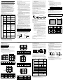 2
2
-
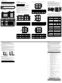 3
3


Mitsubishi Electric GT25 Open Frame Model Le manuel du propriétaire
- Taper
- Le manuel du propriétaire
dans d''autres langues
Documents connexes
-
Mitsubishi Electric GT25 Le manuel du propriétaire
-
-
-
-
-
-
-
