
1
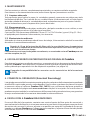
BATTERY OPERATED HYDRAULIC PULLER TYPE PUNCHING TOOL
OUTIL HYDRAULIQUE EMPORTE-PIECE SUR BATTERIE
HYDRAULISCHES AKKU-LOCHSTANZWERKZEUG
HERRAMIENTA HIDRÁULICA PERFORADORA A BATERíA
UTENSILE OLEODINAMICO FORALAMIERE A BATTERIA
B-FL750 B-FL750A B-FL750E B-FL750T
ENGLISH
FRANÇAIS
DEUTSCH
ESPAÑOL
ITALIANO
OPERATION AND MAINTENANCE MANUAL ................................... 6
NOTICE D’UTILISATION ET ENTRETIEN ........................................... 11
BEDIENUNGSANLEITUNG ................................................................... 16
MANUAL DE USO Y MANTENIMIENTO ........................................... 21
MANUALE D’USO E MANUTENZIONE ............................................. 26
14 M 079

2
2
3
3
4
4
4
3
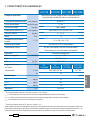
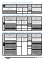
B-FL750
Draw Stud - Tirant
Zugbolzen - Tirante
Draw Stud - Tirant
Zugbolzen - Tirante
Locking ring - Virole
- Kontermutter - Contera
- Ghiera
Die - Matrice - Matrize
Matriz - Matrice
Punch - Poinçon
- Stempel - Punzón - Punzone
Draw Stud - Tirant
Zugbolzen - Tirante
Die - Matrice - Matrize
Matriz - Matrice
Pilot hole
Avant-trou
Pilotbohrung
Agujero piloto
Preforo pilota
1
40
FIG. / BILD 1

3
1 + 3
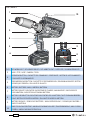
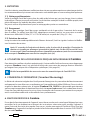
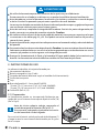
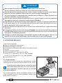
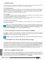
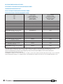
LED WORKLIGHT / ECLAIRAGE PAR LED / LED ARBEITSLICHT / LUCES LED / ILLUMINAZIONE LED
2
HEAD / TETE / KOPF / CABEZA / TESTA
4
OPERATING BUTTON / GACHETTE DE COMMANDE / STARTKNOPF / BOTÓN DE ACCIONAMIENTO
/ PULSANTE DI AZIONAMENTO
5
PRESSURE RELEASE BUTTON / GACHETTE DE DECOMPRESSION / DRUCKABLASSKNOPF / BOTÓN
DESBLOQUEO PRESIÓN / PULSANTE DI RILASCIO
6
BATTERY / BATTERIE / AKKU / BATERÍA / BATTERIA
7
BATTERY CAPACITY INDICATOR / INDICATEUR DE CHARGE / AKKUANZEIGE / INDICADOR DE
CARGA BATERIA / INDICATORI AUTONOMIA BATTERIA
8
BATTERY CHECK BUTTON / BOUTON POUR CONTROL DE LA BATTERIE / TASTE FÜR AKKUÜBERPRÜ-
FUNG / BOTÓN DE CONTROL BATERÍA / PULSANTE DI VERIFICA BATTERIA
9
BATTERY RELEASE / DEBLOCAGE BATTERIE / AKKU ENTRIEGELUNG / DESBLOQUEO BATERÍA /
SBLOCCO BATTERIA
10
RING FOR SHOULDER STRAP / ANNEAU POUR BANDOULIERE / TRAGERIEMENRING / ANILLO PARA
CORREA / ANELLO AGGANCIO TRACOLLA
FIG. / BILD 2
3
10
4
5
6
2
1
9
8
7

4
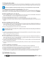
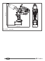
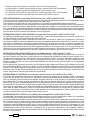
FIG. / BILD 3
FIG. / BILD 4
NO
NON
NEIN
OK
Waste slug
Copeau de perçage
Stanzabfall
Virutas de perforación
Sfrido di tranciatura
4
Draw Stud - Tirant
Zugbolzen - Tirante
Punch - Poinçon
Stempel - Punzón
Punzone
Die - Matrice
Matrize - Matriz
Matrice
5

5
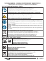
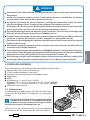
– When operating the tool, keep hands away from the danger zone.
– Au cours de l'utilisation, tenir les mains éloignées de la zone de danger.
– Während der Arbeit nicht mit den Händen in den Gefahrenbereich fassen.
– Durante su utilización, mantenga las manos fuera de la zona de peligro.
– Durante l'utilizzo, mantenere le mani fuori dalla zona di pericolo.
WARNING SYMBOLS - SYMBOLES D'AVERTISSEMENT - WARNSYMBOLE -
SÍMBOLOS DE ADVERTENCIA - SIMBOLI DI AVVERTENZA
Tool - Outil - Werkzeug - Herramienta - Utensile
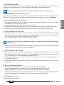
– Before using the tool, carefully read the instructions in this manual.
– Avant d'utiliser cet outil, lire attentivement les instructions de cette notice.
– Vor Inbetriebnahme unbedingt die Bedienungsanleitung durchlesen.
– Antes de utilizar la herramienta, leer atentamente las instrucciones en este manual.
– Prima di utilizzare l'utensile, leggere attentamente le istruzioni riportate in questo manuale.
– Ensure appropriate Personal Protective Equipment (PPE) is used - including hand and eye protection.
– Assurez-vous d'utiliser équipements de protection individuelle (EPI) y compris la protection pour
les mains et les yeux.
– Achten Sie darauf geeignete persönliche Schutzausrüstung (PSA) zu verwen den, einschließlich
für Hände und Augen.
– Asegúrese de utilizar el equipo de protección personal (EPP) que incluye protección para las anos
y los ojos.
– Assicurarsi di utilizzare adeguati dispositivi di protezione personale (DPI) incluse protezioni per
mani e occhi.
– Never throw batteries into re or water.
– Jamais jeter les batteries dans le feu ou dans l'eau.
– Werfen Sie Akkus nicht ins Feuer oder Wasser.
– Nunca tire las baterías al fuego o al agua.
– Mai gettare le batterie nel fuoco o in acqua.
– Always recycle the batteries.
– Recycler toujours les batteries.
– Verbrauchte Akkus stets dem Recycling zuführen.
– Reutilizar siempre las baterías.
– Riciclare sempre le batterie.
– Do not discard batteries into domestic refuse or waste disposal.
– Ne pas jeter de batteries dans une poubelle ou autre lieu non prévu à cet e et.
– Verbrauchte Akkus nicht der allgemeinen Abfallentsorgung zuführen.
– No tirar las baterías al cubo de basura o lugar parecido.
– Non buttate le batterie fuori uso nei cestini della spazzatura o luoghi simili.
– User information (Directives 2011/65/EU and 2012/19/EU), see page 9.
– Information pour les utilisateurs (Directives 2011/65/EU et 2012/19/EU) voir page 14.
– Information für den Benutzer (Richtlinien 2011/65/EU und 2012/19/EU) siehe Seite 19.
– Informe para los usuarios (Directivas 2011/65/EU y 2012/19/EU) vease página 24.
– Informazione agli utenti (Direttive 2011/65/EU e 2012/19/EU) vedere pagina 29.
Battery - Batterie - Akku - Batería - Batteria

6
(1)
Directive 2006/42/EC, annexe 1, point 1.7.4.2 letter u
L
pA
= weighted continuous acoustic pressure level equivalent.
L
pCPeak
= maximum value of the weighted acoustic displacement pressure at the work place.
L
WA
= acoustic power level emitted by the machine.
(2)
Directive 2006/42/EC, annexe 1, point 2.2.1.1
Weighted root mean square in frequency of the acceleration the upper limbs are exposed to for each biodynamic
reference axis. Tests carried out in compliance with the indications contained in EN ISO 5349-1/2 Standard, and under
operating conditions much more severe than those normally found.
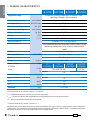
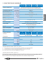
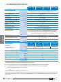
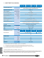
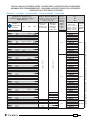
1. GENER AL CHARACTERISTICS
B-FL750 B-FL750E
B-FL750T
B-FL750A
Application range suitable for punching single layers of Stainless Steel,
Mild Steel, Fibreglass, Plastic material
Max. punching capacity
mm (inches)
ø 140 / 5.5
Developed force
kN (US sh. ton)
75 (9)
Minimum operating pressure
bar (psi)
700 (10,000)
Dimensions (ref. to Fig. 5)
mm (inches)
363 x 366 x 83 (14.3 x 14.4 x 3.3)
Weight with battery
kg (lbs)
5,1 (11.2)
Motor
V DC
18
Operating temperature
°C (°F)
-15 to +50 (+5 to +122)
Recommended oil
ENI ARNICA ISO 32 or equivalents
Operating speed
twin speed operation and automatic switching from a rapid
advancing speed of the ram to a slower, more powerful
speed
Safety
maximum pressure valve
Rechargeable battery
V / Ah / Wh
18 / 5.2 / 93.6
Type
CB1852 (Li-Ion)
Weight
kg (lbs)
0,66 (1.45)
Battery charger
ASC30-36
Input
type
EU
27044000
UK
27045000
AUS/NZ
27047000
USA/CAN
27046000
V / Hz
220 - 240 / 50 - 60 115 / 60
W
85
Acoustic noise
(1)
L
pA
dB (A)
73
L
pCPeak
dB (C) 94.5
L
WA
dB (A) 79
Vibration
(2)
m/s
2
0.575 max.
ENGLISH

7
ENGLISH
Do not use the tool for purposes other than those intended by Cembre.
The operator should concentrate on the work being performed and be careful to maintain bal
anced working position.
Before each use check the punches, dies and draw studs, and replace any that are worn or dam-
aged, particularly any punches that have damaged cutting surfaces.
Damaged or improperly assembled accessories can break and hit the operator with su cient
force to cause serious injuries.
Before each use, verify the integrity of the tool; replace any worn, possibly damaged or missing
parts with original Cembre spares.
Only for use in punching holes in single layers of material and thicknesses as shown in tables on pages
32 and 33. Any other use may cause components to break with potential risk of serious injury.
During operation do not allow anyone to pause in the work area, especially in front of the punch.
The use of Cembre punching accessories is recommended. Accessories from other suppliers may
not be designed to withstand the force generated by this tool and may be damaged or break with
potential risk of serious injury.
Protect the tool from rain and moisture. Water will damage the tool and battery.
Electro-hydraulic tools should not be operated in pouring rain.
2. INSTRUCTIONS FOR USE
The part reference includes the following:
Hydraulic tool.
Li-Ion rechargeable battery (2 pcs).
Battery charger (model depends on the tool version).
Shoulder strap.
Carrying case.
ø 11.5 mm Spiral bit (code 6134070).
TD-11 Draw stud with threaded 7/16"-3/4" (code 2685005).
TD-19 Draw stud with threaded 3/4"-3/4" (code 2685008).
USB cable (Ref. to § 5).
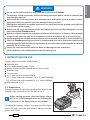
2.1) Preparation
The tool can be easily carried using either the handle or the
shoulder strap attached to ring (10) (Ref. to Fig. 2).
Before starting any work, check the battery charge
(Ref. to § 2.7) and recharge if necessary, following the
instructions in the battery charger user manual.
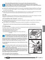
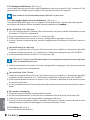
To replace the battery, remove it by pressing the release
button (9), then insert the new battery, sliding it into the
guides until it locks.
Battery
9
WARNING

8
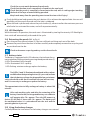
2.2) Head rotation
Two independent joints enable the tool head to turn through 360° and rotate through 180°, allowing
the operator to work in the most comfortable position.
Do not attempt to turn the head when the hydraulic circuit is pressurised.
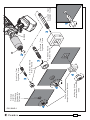
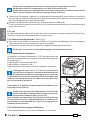
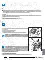
2.3) Assembling of the accessories (Ref. to Fig. 1)
Consult the tables on pages 32 and 33 and select the RD... Punching Kit suitable for the hole to be
made. For punching requirements other than those listed, please contact Cembre.
Round holes ø 15.5 to 30.5 mm
1 Drill a pilot hole in the plate at the desired point, using the ø 11.5 mm spiral bit supplied with the
tool.
2 Fully screw the TD-11 draw stud into the ram (40).
3 Thread the die onto the draw stud, pushing it to rest on the head.
4 Insert the draw stud into the pilot hole and screw the punch onto the draw stud until its cutting
edges are touching the back of the layer of material being punched.
Round holes ø 28.5 to 80.5 mm
1 Drill a pilot hole in the plate at the desired point, using a ø 20 mm spiral bit; alternatively, it is
possible to make the pilot hole with the ø 11.5 mm spiral bit supplied with the tool and widen it
with the KIT RD20.5SS.
2 Fully screw the TD-19 draw stud into the ram (40).
TD-19 draw stud is threaded 3/4" at both ends, screw the short thread into the ram.
3 Thread the die onto the draw stud, pushing it to rest on the head and continue as described in
point 4 above.
Round holes ø 100 to 120 mm
1 Drill a pilot hole in the plate at the desired point, using a ø 29 mm spiral bit; alternatively, it is
possible to make the pilot hole with the ø 11.5 mm spiral bit supplied with the tool and widen it
with the KIT RD30.5SS.
2 Thread the die onto the TD-28.5 draw stud (supplied with the Punching Kit) before screwing it
into the ram.
3 Fully screw the draw stud into the ram (40) and continue as described in point 4 above.
Square and rectangular holes
1 With a drill make the required pilot hole in the plate at the desired point.
2 Fully screw the draw stud (supplied with the Punching Kit) into ram (40) of the head.
3 Thread the die into the draw stud, pushing it to rest on the head.
4 Insert the draw stud into the pilot hole, thread the punch onto the draw stud until its cutting
edges are touching the back of the layer of material being punched then fully screw the locking
ring onto the draw stud to lock the punch in place.
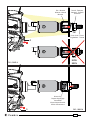
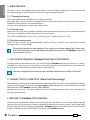
2.4) Punching (Ref. to Fig. 3)
Before punching:
ENGLISH

9
ENGLISH
Check the correct match between die and punch.
Check that the draw stud is completely screwed into the ram head.
Check that the punch is completely screwed onto the stud, with its cutting edges touching
the back of the layer of material being punched.
Keep hands away from the punching zone to avoid serious risk of injury!
Firmly hold the tool and operate the push-button (4) to achieve the required hole: the ram will
gradually pull the punch forward until the hole is produced.
When the hole is performed, release the push-button (4), otherwise after the maximum pressure
relief valve has activated the motor, and will stop automatically.
2.5) LED Worklights
Whilst the tool is in operation, the work area is illuminated by two high luminosity LED Worklights
that switch o automatically at the end of the cycle.
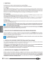
2.6) Retracting the punch (Ref. to Fig. 4)
Press the pressure release button (5), the ram will back and the punch out of the hole.
Remove the punch from the draw stud then carefully and completely remove the scrap slug and
any residue from the die.
Check and remove scrap slug and any residue from the die.
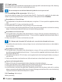
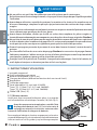
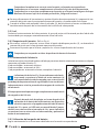
2.7) Battery status
The battery is equipped with LED indicators that indicate the re-
maining battery life at any time by pressing the adjacent button (7):
4 LEDs illuminated: fully charged
2 LEDs illuminated: 50 % capacity
1 LED flashing: minimum charge, replace the battery.
Tool LEDs (1and 3) illuminated combined with an alarm
audible when the operating button (4) is pressed, indicate
that the battery voltage has dropped below a minimum
safety threshold; under these conditions the tool will not start,
and it is necessary to recharge or replace the battery.
The approximate time to fully recharge a battery is about 100
minutes.
After each working cycle, and after the extraction of the
battery from the tool, an integrated battery cut-o device
will operate after 70 s approx. Then the LED nearest to
button (P) will ash 5 times each 14 s approx. The battery will
be reactivated when it is reintroduced into the tool and the
operating button is pressed.
2.8) Using the battery charger
Carefully follow the instructions in the battery charger user manual.
7
3
1
4

10
3. MAINTENANCE
The tool is robust, completely sealed, and requires very little daily maintenance. Compliance with
the following points, should help to maintain its optimum performance:
3.1) Thorough cleaning
Dust, sand and dirt are a danger for any hydraulic device.
Every day, after use, the tool must be wiped with a clean cloth taking care to remove any residue,
especially close to pivots and moveable parts.
Do not use hydrocarbons to clean the rubber parts.
3.2) Storage case
When not in use, the tool should be stored and transported in the plastic case, to prevent damage.
The case is suitable for storing the tool and the accessories.
VAL-P56: Size 690x446x179 mm (27.1x17.5x7.0 inches) , weight 5,5 kg (12.1 lbs).
3.3) Routine maintenance
When the tool reaches the predetermined number of hours worked, it will signal that routine
maintenance is recommended.
The tool will continue to work however 15 sec. after use an alarm comprising 3 beeps com-
bined with illumination of the worklights will signal that its return to Cembre for service is
recommended (see § 6).
4. USE OF NON ORIGINAL Cembre PUNCHING ACCESSORIES
To obtain the best operating results, the use of original Cembre punching accessories is recom-
mended; as an alternative, it is possible to use punching accessories made by other manufacturers
by requesting separately the speci c adaptor (see page 34).
Check the compatibility of the accessories with the characteristics of the B-FL750 tool.
5. CONNECTION TO COMPUTER (Smartool thecnology)
The memory card integrated in the tool records operating data for transfer via the USB cable supplied.
To view and manage this data, go to www.cembre.com and register in the dedicated area, then
download the free Cembre software CEM_SWBT01.
Keeping the Firmware of the tool updated, via free of charge download from here, will optimise
the tool’s performance.
6. RETURN TO Cembre FOR OVERHAUL
In the case of a breakdown contact our Area Agent who will advise you on the problem and give
you the necessary instructions on how to dispatch the tool to our nearest service Centre; if possible,
attach a copy of the Test Certi cate supplied by Cembre together with the tool or ll in and attach
the form available in the “ASSISTANCE” section of the Cembre website.
ENGLISH

11
1. CARACTERISTIQUES GENER ALES
B-FL750 B-FL750E
B-FL750T
B-FL750A
Domaine d'application: conçu pour percer des tôles d’acier inoxydable, l’acier
doux, des parois en bre de verre et la matière plastique
Capacité de percage maxi. mm (inches) ø 140 / 5.5
Force développée
kN (US sh. ton)
75 (9)
Pression min. de travail
bar (psi) 700 (10,000)
Dimensions (voir Fig. 5) mm (inches) 363 x 366 x 83 (14.3 x 14.4 x 3.3)
Poids avec batterie
kg (lbs) 5,1 (11.2)
Moteur V DC 18
Température de fonction-
nement:
°C (°F) -15 à +50 (+5 à +122)
Huile recommandée: ENI ARNICA ISO 32 ou équivalents
Avance rapide:
l’outil passe automatiquement de la vitesse rapide
à la vitesse lente de perçage
Sécurité valve de surpression
Batterie rechargeable V / Ah / Wh 18 / 5.2 / 93.6
Type CB1852 (Li-Ion)
Poids kg (lbs) 0,66 (1.45)
Chargeur de batterie
ASC30-36
Alimentation
type
EU
27044000
UK
27045000
AUS/NZ
27047000
USA/CAN
27046000
V / Hz 220 - 240 / 50 - 60 115 / 60
W85
Bruit aérien sonore
(1)
L
pA
dB (A)
73
L
pCPeak
dB (C)
94.5
L
WA
dB (A) 79
Vibrations
(2)
m/s
2
0.575 maxi.
(1)
Directive 2006/42/CE, annexe 1, point 1.7.4.2, lettre u
L
pA
= niveau de pression sonore continue équivalente pondérée A sur le poste de travail.
L
pCPeak
= valeur de pression sonore instantanée pondérée C sur le poste de travail.
L
WA
= niveau de puissance acoustique dégagée par la machine.
(2)
Directive 2006/42/CE, annexe 1, point 2.2.1.1
Valeur quadratique moyenne pondérée en fréquence de l'accélération à laquelle sont exposés les membres supérieurs
pour chaque axe biodynamique de référence. Relevés réalisés suivant les indications de la Norme EN ISO 5349-1/2,
dans des conditions de service largement représentatives des conditions d'emploi normales.
FRANÇAIS

12
FRANÇAIS
Ne pas utiliser cet outil à des ns di érentes que celles prévues par le constructeur.
Restez bien attentif tout au long du travail, ne soyez pas distrait, ne perdez pas l’équilibre pendant
l'utilisation.
Avant chaque utilisation, contrôler les poinçons, les matrices et les tirants et les remplacer en cas
d'usure ou dommage, remplacer les poinçons qui présenteraient des surfaces de coupe endom-
magées.
Des accessoires endommagés ou mal montés peuvent se rompre et atteindre l’opérateur avec une
force su sante pour provoquer des lésions graves.
Avant chaque utilisation, véri er que la tête est en bon état; remplacer les pièces usagées et
éventuellement endommagées ou manquantes avec des pièces de rechange originales Cembre.
Ne pas faire de trous à travers deux couches ou plus de matériau ou avec des épaisseurs supérieure
à celles indiquées dans le tableau de la page 32 et 33; ceci pourrait provoquer la rupture du tirant
ou du poinçon et des conséquences également graves pour la sécurité des personnes.
Durant le perçage ne permettre à personne de rester dans la zone de travail, surtout devant le
poinçon.
Il est conseillé d’utiliser des accessoires de perçage Cembre. Les accessoires de perçage d’autres
fabricants pourraient s’abîmer ou ne pas résister à la force générée par cet outil ce qui aurait des
conséquences également graves pour la sécurité des personnes.
Protéger l’outil de la pluie et de l’humidité. L’eau pourrait endommager l’outil et la batterie, les
outils hydro-electriques ne devraient pas être utilisés sous la pluie.
2. INSTRUC TIONS D'UTILISATION
L' ensemble comprend:
Outil hydraulique pour percer.
Batterie rechargeable Li-Ion (2 pcs).
Chargeur de batterie (di érent en fonction de la version de l'outil).
Bandoulière.
Co ret de rangement.
Foret hélicoïdal ø11.5 mm (cod. 6134070).
Tirant “TD-11” leté 7/16"-3/4" (cod. 2685005).
Tirant “TD-19” leté 3/4"-3/4" (cod. 2685008).
Câble USB (Voir § 5).
2.1) Mise en service
L’outil peut être transporté facilement grâce à sa poignée
et à la bandoulière accrochée par l'anneau (10) (Voir Fig. 2).
Avant de commencer toute opération, contrôler l’état
de charge de la batterie (voir § 2.7) et si nécessaire, la
recharger en suivant les instructions contenues dans
le manuel d’utilisation du chargeur de batteries.
Pour remplacer la batterie, la retirer en appuyant sur le méca-
nisme de déblocage (9), puis introduire la nouvelle batterie en
la faisant coulisser sur les guides jusqu’au blocage complet.
Batterie
9
AVERTISSEMENT

13
FRANÇAIS
2.2) Rotation de la tête
La tête de l'outil, grâce à deux rotules indépendantes, peut tourner de 360° et pivoter de 180° par
rapport au corps, permettant à l'utilisateur de travailler dans la meilleure position.
Ne pas forcer la rotation de la tête, lorsque le circuit hydraulique est sous pression.
2.3) Montage des accessoires (Réf. a Fig. 1)
En consultant le tableau de la page 32 et 33, choisir le KIT de perforation RD... adapté au trou à
e ectuer. Pour des exigences de perçage di érentes de celles indiquées, contacter Cembre.
Trous ronds de ø 15,5 mm à 30,5 mm
1 A l’aide d’une perceuse, faire un avant-trou dans la tôle à l’endroit établi en utilisant le foret
hélicoïdal ø 11.5 mm fourni avec l'outil.
2 Visser complètement le tirant TD-11 dans le piston (40).
3 En ler correctement la matrice dans le tirant en la poussant pour qu’elle s’appuie sur la tête.
4 Insérer le tirant dans le trou déjà percé et visser le poinçon sur le tirant jusqu’à la tôle.
Trous ronds de ø 28,5 à 80,5 mm
1 A l’aide d’une perceuse, faire un avant-trou dans la tôle à l’endroit établi en utilisant un foret
hélicoïdal ø 20 mm; comme alternative il est possible de faire le avant-trou avec le foret hélicoïdal
ø 11.5 mm fourni avec l'outil et l’élargir avec le KIT RD20.5SS.
2 Visser complètement le tirant TD-19 dans le piston (40).
Le tirant TD-19 est leté 3/4” aux deux extrémités; visser dans le piston le côté avec le letage
le plus court.
3 En ler correctement la matrice dans le tirant en la poussant pour qu’elle s’appuie sur la tête et
continuer comme décrit dans le point 4 précédente.
Trous ronds de ø 100 à 120 mm
1 A l’aide d’une perceuse, faire un avant-trou dans la tôle à l’endroit établi en utilisant un foret
hélicoïdal ø 29 mm; comme alternative il est possible de faire le avant-trou avec le foret hélicoïdal
ø 11.5 mm fourni avec l'outil et l’élargir avec le KIT RD30.5SS.
2 En ler correctement la matrice dans le tirant TD-28.5 (fourni avec le kit de perçage) avant son
vissage dans le piston.
3 Visser complètement le tirant dans le piston (40) et continuer comme décrit dans le point 4
précédente.
Trous carrés et rectangulaires
– A l’aide d’une perceuse, faire un avant-trou dans la tôle à l’endroit établi.
– Visser complètement le tirant (fourni avec le kit de perçage) dans le piston (40).
– En ler la matrice dans le tirant en la poussant pour qu’elle s’appuie sur la tête.
– Insérer le tirant dans le trou puis insérer le poinçon sur le tirant jusqu’à ce qu’il bute contre la tôle.
– Visser complètement la vis de blocage sur le tirant pour bloquer l’ensemble.
2.4) Perçage (Réf. a Fig. 3)
Avant d’e ectuer le perçage:

14
FRANÇAIS
Véri er que le couplage entre la matrice et le poinçon correspondant est correct.
Véri er que le tirant est complètement vissé dans le piston de la tête.
Véri er que le poinçon est complètement vissé sur le tirant jusqu’à ce qu’il bute contre la tôle.
Tenir les mains éloignées de la zone de perçage. Risque de lésions!
Tenez l'outil fermement y appuyer sur la gâchette de commande (4) pour mettre en marche le
groupe moteur pompe, le mouvement du piston commencera entraînant ainsi le déplacement
en avant du poinçon et le perçage de la tôle.
Relâchez la gâchette de commande (4) lorsque la coupe est e ectuée.
Si l'on maintient le moteur actionné, l’outil s’arrêtera automatiquement avec l'intervention de la
valve de surpression.
2.5) Led
Lors de l’actionnement de l’outil, la zone de travail est éclairée au moyen de deux LED haute lumi-
nosité qui s’éteignent automatiquement à la n du cycle.
2.6) Réouverture del poinçon (Réf. a Fig. 4)
Pour rouvrir l'ensemble, en appuyant à fond sur la gâchette de déblocage (5) on provoque le
retour du piston et par conséquent le retour du poinçon.
Démonter le poinçon du tirant et expulser le copeau de perçage de la matrice.
Véri er qu’il ne reste aucun résidu de découpage à l’intérieure de la matrice.
2.7) Autonomie de la batterie
La batterie est équipée d’indicateurs à LED qui permettent de
contrôler, à tout moment, son autonomie résiduelle en appuyant
sur le bouton (7):
4 led allumées: autonomie maximale
2 led allumées: autonomie à 50 %
1 led clignotante: autonomie minimale, remplacer la batterie.
L'éclairage des deux Led (1 et 3) associé à l’avertisseur
sonore lorsque l’on appuie sur le bouton de déclenchement
(4 indique que la batterie est déchargée et que sa tension
est descendue au-dessous du seuil minimal de sécurité; dans cette
situation, l’outil ne démarre pas, il est donc nécessaire de rechar-
ger ou de remplacer la batterie.
À titre indicatif, le délai de recharge complète de la batterie cor-
respond à environ 100 min.
A la n de chaque cycle de travail comme à l’extraction de
la batterie de l’outil, un dispositif électronique arrête auto-
matiquement la batterie après environ 70 s.
Pour con rmer cette opération, la led la plus proche du bouton
(P) clignotera 5 fois en 14 s (approximativement). La batterie est
réactivée dès sa réintroduction dans l’outil, ou en appuyant sur
le bouton d’actionnement.
2.8) Utilisation du chargeur de batterie
Suivre attentivement les instructions indiquées sur le manuel.
7
3
1
4

15
FRANÇAIS
3. ENTRETIEN
L'outil est robuste, complètement scellé et ne nécessite aucune préoccupation ou attention particulier.
Les recommandations qui suivent sont néanmoins souhaitables pour assurer une longévité optimum:
3.1) Nettoyage élémentaire
Veiller à protéger l'outil de la poussière, du sable et de la boue qui sont un danger à tout système
hydraulique. Chaque jour après utilisation, l'outil doit être nettoyé à l'aide d'un chi on propre, tout
particulièrement aux endroits de pièces mobiles.
Ne jamais utiliser d’hydrocarbures pour le nettoyage des parties en caoutchouc.
3.2) Rangement
Au repos, pour protéger l'outil des coups accidentels et de la poussière, il convient de le ranger
dans le co ret. Ce co ret (type VAL-P56), adapté pour contenir l'outil et ses accessoires a comme
dimensions: 690x446x179 mm (27.1x17.5x7.0 inches) et un poids de 5,5 kg (12.1 lbs).
3.3) Entretien de routine
Lorsqu'on atteint le nombre prédéterminé d'heures de travail, l'outil va signaler la nécessité d'e ec-
tuer l'entretien de routine.
Après 15 secondes de l'exécution du dernier cycle, la nécessité de procéder à l'entretien de
routine est signalée par allumages intermittents répétés trois fois des LED associé à l’aver-
tisseur sonore. L'outil continue par ailleurs à travailler normalement; mais il est recommandé
de le renvoyer à Cembre pour une révision complète (voir § 6).
4. UTILISATION DES ACCESSOIRES DE PERÇAGE NON ORIGINAUX Cembre
Pour obtenir les meilleurs résultats opérationnels, il est conseillé d'utiliser des accessoires de perçage
originaux Cembre, sinon il est possible d'utiliser des accessoires de perçage d'autres fabricants
qui exigent leurs propres kits d’adaptation spéci ques (Voir page 34).
Véri er la compatibilité des accessoires avec les caractéristiques de l'outil B-FL750.
5. CONNEXION À L’ORDINATEUR (Smartool thecnology)
Le chier de mémoire intégrée dans l’outil permet d’enregistrer les paramètres de fonctionnement
et de pouvoir les transférer vers un ordinateur par l’intermédiaire du câble USB fourni. Pour visualiser
et gérer les données mémorisées, le logiciel Cembre CEM_SWBT01 est disponible gratuitement
après enregistrement dans le domaine réservé du site www.cembre.com. Dans ce domaine réservé,
il sera alors possible de trouver les mises à jour éventuelles des rmwares permettant à vos propres
outils une meilleure e cacité et d’améliorer leurs performances.
6. ENVOI EN REVISION A Cembre
En cas de dysfonctionnement de l’appareil, merci de vous adresser à notre Agent Régional qui vous
conseillera et le cas échéant vous donnera les instructions nécessaires pour envoyer l’appareil à
notre Centre de Service le plus proche. Dans ce cas, joindre une copie du Certi cat d’Essai livré par
Cembre avec l’appareil ou remplir et joindre le formulaire disponible dans la section “ASSISTANCE”
du site web Cembre.

16
1. ALLGEMEINE EIGENSCHAFTEN
(1)
Richtlinie 2006/42/EG, Anhang 1, Nummer 1.7.4.2, Buchstabe u
L
pA
= Stufe konstanter Emissionsschalldruckpegel entsprechend Gewichtung A am Arbeitsplatz.
L
pCPeak
= maximaler Emissionsschalldruckpegel entsprechend Gewichtung C am Arbeitsplatz.
L
WA
= Emissionsschalldruckpegel durch das Gerät
(2)
Richtlinie 2006/42/EG, Anhang 1, Nummer 2.2.1.1
Der durchschnittliche Schwingungsgesamtwert dem die oberen Körpergliedmaßen ausgesetzt sind, wurde technisch
vergleichbar nach EN ISO 5349-1/2 einer repräsentativen Maschine ermittelt und übersteigt nicht den vorgeschrie-
benen Wert.
B-FL750 B-FL750E
B-FL750T
B-FL750A
Anwendungsbereich geeignet zum Stanzen von rostfreiem Stahlblech, Weichstahl,
Material aus Glasfaser- und Kunststo material
Max. Stanzbereich: mm (inches) ø 140 / 5.5
Stanzkraft:
kN (US sh. ton)
75 (9)
Arbeitsdruck bar (psi) 700 (10,000)
Abmessungen (siehe Bild 5) mm (inches) 363 x 366 x 83 (14.3 x 14.4 x 3.3)
Gewicht inkl. Akku kg (lbs) 5,1 (11.2)
Motor V DC 18
Betriebstemperatur: °C (°F) -15 bis +50 (+5 bis +122)
Empfohlenes Öl: ENI ARNICA ISO 32 oder ähnliches
Kolbenvorschub:
Das Werkzeug ist mit einer Doppelkolbenhydraulikausgerü-
stet. Beim Beginn des Arbeitsvorganges wird automatisch
auf den langsameren Arbeitshub umgeschaltet
Sicherheit: Überdruckventil
Wiederau adbarer Akku V / Ah / Wh 18 / 5.2 / 93.6
Typ CB1852 (Li-Ion)
Gewicht kg (lbs) 0,66 (1.45)
Akkuladegerät
ASC30-36
Eingangspannung
Typ
EU
27044000
UK
27045000
AUS/NZ
27047000
USA/CAN
27046000
V / Hz 220 - 240 / 50 - 60 115 / 60
W85
Lärmschutzbestimmung
(1)
L
pA
dB (A)
73
L
pCPeak
dB (C) 94.5
L
WA
dB (A) 79
Vibrationen
(2)
m/s
2
0.575 max.
DEUTSCH

17
DEUTSCH
Verwenden Sie das Akkuwerkzeug ausschließlich für den vom Hersteller vorgesehenen Anwen-
dungszweck.
Arbeiten Sie konzentriert und lassen Sie sich während des Einsatzes nicht ablenken und nehmen
zur Arbeit eine sichere und standfeste Arbeitsposition ein!
Vor jeglicher Benutzung die Stempel, Matrizen, und Zugbolzen überprüfen und bei Verschleiß
oder Beschädigung ersetzen. Stempel mit beschädigten Schnittkanten ersetzen.
Beschädigte oder falsch montierte Werkzeuge können Brechen und Personen mit einer dermaßen
großen Kraft tre en, dass diese schwere Verletzungen davontragen können.
Vor jeder Benutzung die Unversehrtheit des Kopfes überprüfen. Verschlissene, beschädigte oder
fehlende Teile durch Originalersatzteile von Cembre ersetzen.
Es dürfen keine Stanzungen mit zwei oder mehreren Materialschichten und höheren Material-
stärken als in Tabellen auf den Seite 32 und 33 angegeben ist, durchgeführt werden.
Das könnte zur Beschädigung des Zugbolzens oder des Stempels führen und es besteht eine große
Gefahr für das Personal.
Während der Stanzung niemandem erlauben, im Arbeitsbereich zu verweilen, vor allem darf sich
niemand vor dem Stempel aufhalten.
Es wird die Verwendung des Stanzzubehörs von Cembre empfohlen. Stanzzubehör anderer Her-
steller könnte sich beschädigen oder der von diesem Werkzeug erzeugten Kraft nicht stand halten.
Daraus leitet sich eine große Gefahr für die Unversehrtheit des Personals ab.
Das Werkzeug vor Regen und Feuchtigkeit schützen. Wasser könnte das Werkzeug und den Akku
beschädigen. Elektrohydraulische Werkzeuge sollten nicht im Regen eingesetzt werden.
2. BEDIENUNGSHINWEISE
Zum Lieferumfang unter dieser Bezeichnung gehören folgende Teile:
Hydraulisches Akku-Lochstanzwerkzeug.
2 Stück wiederaufladbare Li-Ion Akkus.
Ladegerät (entsprechend der Länderkon guration).
Trageriemen.
Ko er.
Spiralbohrer ø11.5 mm (Art.Nr. 6134070).
Zugbolzen “TD-11” mit ein Gewinde 7/16"-3/4" (Art.Nr. 2685005).
Zugbolzen “TD-19” mit ein Gewinde 3/4"-3/4" (Art.Nr. 2685008).
USB-Kabel (siehe Punkt 5).
2.1) Vorbereitung
Das Werkzeug kann bequem am Gri oder mit dem Trage-
riemen, der am Ring (Bild 6 T.10) befestigt ist, transportiert
werden.
ÜberprüfenSie vor jedem Arbeitsvorgang den Ladezu-
stand der Akkus (siehe Pkt. 2.7) und laden Sie bei Bedarf
die Akkus entsprechend den Anweisungen in der Be-
dienungsanleitung des Akkuladegerätes auf.
Drücken Sie für den Akkuaustausch auf die Entriegelung
(9) und führen Sie den neuen Akku bis zum Einratsen ein.
Akku
9
HINWEISE

18
2.2) Drehbewegung des Kopfes
Der Kopf des Werkzeuges kann um 360° gedreht werden und der Stanzkopf kann noch um max.
180° abgewinkelt werden.
Der Kopf darf keinesfalls in eine andere Position gedreht werden, während das Werkzeug
unter Druck steht.
2.3) Montagezubehör (siehe Bild 1)
Aus den Tabellen auf den Seite 32 und 33 das entsprechende KIT RD... auswählen.
Bei hier nicht aufgeführten Anforderungen an die Stanzung bitte mit Cembre Kontakt aufnehmen.
Rundstanzungen von ø 15,5 bis 30,5 mm
1 Zur Führung mit einer Bohrmaschine am festgelegten Punkt eine Pilotbohrung in das Blech bohren.
Die Pilotbohrung mit dem Spiralbohrer der Größe ø11.5mm ausführen, der zum Lieferumfang
gehört.
2 Den Zugbolzen TD-11 vollständig in den Kolben (40) des Kopfes eindrehen.
3 Die Matrize auf den Zugbolzen aufsetzen und sie bis zum Anschlag an den Kopf schieben.
4 Den Zugbolzen in die Pilotbohrung einführen und den Stempel auf den Zugbolzen bis zum Blech
aufschrauben.
Rundstanzungen von ø 28,5 bis 80,5 mm
1 Zur Führung mit einer Bohrmaschine am festgelegten Punkt eine Pilotbohrung in das Blech
bohren. Dabei einen Spiralbohrer ø20 mm benutzen. Alternativ dazu kann die Pilotbohrung mit
dem Bohrer der Größe ø 11.5 mm ausgeführt werden. Anschließend die Bohrung mit dem
KIT RD20.5SS erweitern.
2 Den Zugbolzen TD-19 vollständig in den Kolben (40) des Kopfes eindrehen.
Der Zugbolzen TD-19 hat an beiden Enden ein 3/4"-Gewinde. In den Kolben des Werkzeuges
die Seite mit dem kürzeren Gewinde eindrehen.
3 Die Matrize auf den Zugbolzen aufsetzen und sie bis zum Anschlag an den Kopf schieben.
Entsprechend Punkt 4 fortfahren.
Rundstanzungen von ø 100 bis 120 mm
1 Zur Führung mit einer Bohrmaschine am festgelegten Punkt eine Pilotbohrung in das Blech
bohren. Dabei einen Spiralbohrer ø29 mm benutzen. Alternativ dazu kann die Pilotbohrung mit
dem Bohrer der Größe ø 11.5 mm durchgeführt werden Anschließend die Bohrung mit dem
KIT RD30.5SS erweitern.
2 Vor der Montage des Zugbolzen TD-28.5 (er ist im Lieferumfang des KIT RD.. enthalten) die Matrize
auf den Zugbolzen aufsetzen und dann in den Kolben des Werkzeuges schrauben.
3 Den Zugbolzen vollständig in den Kolben (40) eindrehen.
Entsprechend Punkt 4 fortfahren.
Quadratische und rechteckige Stanzungen
1 Zur Führung am festgelegten Punkt mit einer Bohrmaschine eine Pilotbohrung in das Blech bohren.
2 Den Zugbolzen vollständig in den Kolben (40) einschrauben (er ist im Lieferumfang des KIT RD..
enthalten).
3 Die Matrize auf den Zugbolzen aufsetzen und sie bis zum Anschlag an den Kopf schieben.
4 Den Zugbolzen in die Pilotbohrung einsetzen und den Stempel auf dem Zugbolzen bis zum Blech
schieben. Die Kontermutter vollständig auf den Zugbolzen aufschrauben, um alle Bauteile zu
xieren.
2.4) Stanzung (siehe Bild3)
Vor dem Stanzen folgendes beachten:
DEUTSCH

19
DEUTSCH
Die korrekte Montage der Matrize am entsprechenden Stempel kontrollieren.
Die vollständige Verschraubung des Zugbolzens im Kolben des Kopfes überprüfen.
Die vollständige Verschraubung des Stempels auf dem Zugbolzen (bis zum Blech) überprüfen.
Nicht in den Stanzbereich fassen. Verletzungsgefahr!
Halten Sie das Werkzeug fest und durch Drücken des Startknopfes (4) beginnen Motor und Pumpe
zu arbeiten und der Kolben beginnt sich zu bewegen, der Stempel bewegt sich und es erfolgt
das Stanzen des Bleches.
Wenn die Stanzung erfolgt ist, den Startknopf (4) loslassen. Ansonsten erfolgt automatisch die
Abschaltung bei Erreichen des Maximaldruckes durch das Überdruckventil.
2.5) LED
Während der Betätigung des Werkzeugs wird der Arbeitbereich von zwei LED-Anzeigen mit hoher
Helligkeit ausgeleuchtet, die sich am Zyklusende automatisch abschalten.
2.6) Zurückfahren des Stempels (siehe Bild4)
Um den Stempel zurückzufahren, drücken Sie kräftig des Druckablassknopf (5) bis sich der Kolben
vollständig zurückgezogen hat.
Den Stempel vom Zugbolzen abmontieren und den Stanzabfall aus der Matrize entfernen.
Überprüfen Sie, dass keine Stanzrückstände innerhalb der Matrize zurückbleiben.
2.7) Akkuladung
Die Akku ist mit LED-Anzeigen ausgestattet, die jederzeit über die verbleibende Akkulaufzeit Aus-
kunft gibt, indem man auf die Taste (7) drückt:
4 LED eingeschaltet: Maximale Ladung
2 LED eingeschaltet: Ladung zu 50 %
1 LED blinkend: Minimale Ladung, Akku austauschen bzw.
au aden.
Wenn der Akku nicht mehr ausreichende Ladung hat, wird
beim Betätigen des Startknopfes (4) über die LED Leuchten
(1 und 3) zusammen mit einem akustischen Signal das
Erreichen des Mindestsicherheitsniveau signalisiert. Unter diesen
Bedingungen kann das Werkzeug nicht in Betrieb genommen
werden. Laden Sie den Akku auf oder tauschen Sie ihn aus.
Ein vollständiger Ladevorgang eines leeren Akkus dauert etwa
100 Minuten.
Nach jedem Arbeitszyklus und wie auch nach der Entfer-
nung des Akkus schaltet es durch die eingebaute Elektronik
nach ca. 70s automatisch ab.
Als Bestätigung des Vorganges wird die LED bei der Taste (P) 5-mal
hintereinander innerhalb von ca. 14s blinken. Durch das Einführen
des Akkus in das Werkzeug wird der Akku wieder aktiviert oder
durch die Betätigung des Startknopfes.
2.8) Verwendung des Ladegerätes
Die in der Bedienungsanleitung gegebenen Hinweise sind zu beachten.
7
3
1
4

20
3. WARTUNG
Das Werkzeug ist robust und benötigt keine spezielle P ege.
Zur Erhaltung der Garantieansprüche beachten Sie folgende Hinweise:
3.1) P ege
Dieses hydraulische Werkzeug sollte vor starker Verschmutzung geschützt werden, da dies für ein
hydraulisches System gefährlich ist. Jeden Tag nach der Arbeit sollte das Werkzeug mit einem Tuch
von Schmutz und Staub gereinigt werden, besonders die beweglichen Teile. Verwenden Sie keine
Kohlenwassersto e (z.B. Teilereiniger, Bremsenreiniger) zum Reinigen der Gummiteile.
3.2) Lagerung
Wenn das Werkzeug nicht benötigt wird, sollte es in dem Kunststo ko er gelagert werden und ist
somit gegen Beschädigungen wie Stoß und Staub geschützt.
Der Metallko er Typ VAL-P56 hat folgende Abmessungen: 690x446x179 mm (27.1x17.5x7.0 inches)
und ein Gewicht von 5,5 kg (12.1 lbs.). Er ist geeignet zum Lagern vom Werkzeug und Zubehör.
3.3) Wartung
Sobald die vorgegebene Anzahl der maximalen Arbeitsstunden erreicht sind, signalisiert das Werk-
zeug die damit fällige Wartung.
15 Sekunden nach Ausführung des letzten Zyklus, wird eine bevorstehende Wartung,dreimal
hintereinander durch ein unterbrechendes Aufblinken der LED's, zusammen mit einem akus-
tischen Warnsignal angekündigt.
Das Werkzeug wird weiterhin normal arbeiten. Es wird das Einsenden des Werkzeuges an Cembre
empfohlen, für eine komplette Überholung (siehe Pkt. 6).
4. EINSATZ VON STANZWERKZEUGEN VON FREMDLIEFERANTEN
Um beste Ergebnisse zu erzielen, sollte das Originalstanzzubehör von Cembre benutzt werden.
Alternativ dazu kann Stanzzubehör anderer Hersteller mit einem speziellen separat zu bestellenden
Adapter verwendet werden (siehe Seite 34).
Die Kompatibilität von dem Stanzzubehörs anderer Hersteller mit den technischen Daten
vom B-FL750 kontrollieren.
5. ANSCHLUSS AN EINEN COMPUTER (Smartool thecnology)
Der im Werkzeug integrierte Speicher ermöglicht die Betriebsparameter zu speichern und mit dem
mitgelieferten USB-Kabel auf einen Computer zu übertragen.
Um die Daten vom Werkzeug zu übertragen und zu verwalten, müssen Sie unter www.cembre.com
die Cembre Software CEM_SWBT01 nach einer Registrieung downloaden.
Hier nden Sie auch mögliche Firmware Updates für die Platine des Werkzeuges, um eine bestmög-
liche Leistung und E zienz des Werkzeuges zu ermöglichen.
6. EINSENDUNG AN Cembre ZUR ÜBERPRÜFUNG
Sollten an dem Gerät Fehler auftreten, wenden Sie sich bitte an unsere Gebietsvertretung, die
Sie gerne beraten und Ihnen alle nötigen Informationen zum Einsenden des Gerätes an unseren
Hauptsitz geben wird. Wenn vorhanden, legen Sie dem Gerät bitte eine Kopie des von Cembre
mitgelieferten Zerti kates bei oder füllen das, unter dem Bereich “SUPPORT“ der Cembre Website,
verfügbare Formular aus und fügen es bei.
DEUTSCH
La page est en cours de chargement...
La page est en cours de chargement...
La page est en cours de chargement...
La page est en cours de chargement...
La page est en cours de chargement...
La page est en cours de chargement...
La page est en cours de chargement...
La page est en cours de chargement...
La page est en cours de chargement...
La page est en cours de chargement...
La page est en cours de chargement...
La page est en cours de chargement...
La page est en cours de chargement...
La page est en cours de chargement...
La page est en cours de chargement...
La page est en cours de chargement...
-
 1
1
-
 2
2
-
 3
3
-
 4
4
-
 5
5
-
 6
6
-
 7
7
-
 8
8
-
 9
9
-
 10
10
-
 11
11
-
 12
12
-
 13
13
-
 14
14
-
 15
15
-
 16
16
-
 17
17
-
 18
18
-
 19
19
-
 20
20
-
 21
21
-
 22
22
-
 23
23
-
 24
24
-
 25
25
-
 26
26
-
 27
27
-
 28
28
-
 29
29
-
 30
30
-
 31
31
-
 32
32
-
 33
33
-
 34
34
-
 35
35
-
 36
36


dans d''autres langues
- italiano: Cembre B-FL750E Manuale utente
- español: Cembre B-FL750E Manual de usuario
- Deutsch: Cembre B-FL750E Benutzerhandbuch