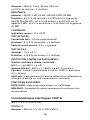
Amprobe AM-35XPA Le manuel du propriétaire
- Catégorie
- Mesure, test
- Taper
- Le manuel du propriétaire

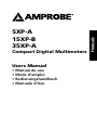
Users Manual
• Mode d’emploi
• Bedienungshandbuch
• Manual d’Uso
• Manual de uso
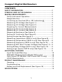
5XP-A
15XP-B
35XP-A
Compact Digital
Multimeters

Compact Digital Multimeters
2A MAX
FUSED
COM A
Hz Temp
V
mA
A
mA
400
1000
A
A
35XP-A
RANGE NON
CONTACT
VOLTAGE
HOLD
V
HZ
V
auto-off
°C
OFF
°F
mA
A
A
1832 400
CAT 600V
CAT 300V
MAX
600V
600V
5
6
4
2
3
1
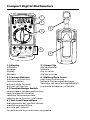
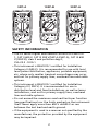
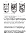
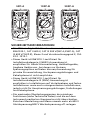
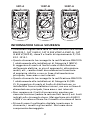
1.) Display
Afficheur
Anzeige
Display
Pantalla
2.) Feature Buttons
boutons de fonctions
funktionstasten
pulsanti delle funzioni
botones de función
3.) Function/Range Switch
commutateur de gamme/fonction.
funktion/bereich-schalter
selettore funzione/portata
selector de la función y del rango
4.) Test Lead Connections
branchements des cordons de test
messleitungsanschlÜsse
boccole per i cavetti
conexiones de los conductores de prueba
5.) Strap Clip
clip de bretelle
klemme
clip in velcro
clip para correa
6.) Battery/Fuse Cover
capot des fusibles/pile
batterie-/Sicherungsabdeckung
Sportello del vano portapile/fusibili
puerta de la batería y el fusible

5XP-A
15XP-B
35XP-A
Compact Digital Multimeters
Users Manual
• Manual de uso
• Mode d’emploi
• Bedienungshandbuch
• Manuale d’Uso
October 2012, Rev.2
©2012 Amprobe Test Tools.
All rights reserved. Printed in Taiwan


5XP-A
15XP-B
35XP-A
Compact Digital Multimeters
Users Manual
• Manual de uso
• Mode d’emploi
• Bedienungshandbuch
• Manuale d’Uso
English

Limited Warranty and Limitation of Liability
Your Amprobe product will be free from defects in material
and workmanship for 1 year from the date of purchase. This
warranty does not cover fuses, disposable batteries or damage
from accident, neglect, misuse, alteration, contamination, or
abnormal conditions of operation or handling. Resellers are not
authorized to extend any other warranty on Amprobe’s behalf.
To obtain service during the warranty period, return the product
with proof of purchase to an authorized Amprobe Test Tools
Service Center or to an Amprobe dealer or distributor. See Repair
Section for details. THIS WARRANTY IS YOUR ONLY REMEDY.
ALL OTHER WARRANTIES - WHETHER EXPRESS, IMPLIED OR
STAUTORY - INCLUDING IMPLIED WARRANTIES OF FITNESS FOR
A PARTICULAR PURPOSE OR MERCHANTABILITY, ARE HEREBY
DISCLAIMED. MANUFACTURER SHALL NOT BE LIABLE FOR ANY
SPECIAL, INDIRECT, INCIDENTAL OR CONSEQUENTIAL DAMAGES
OR LOSSES, ARISING FROM ANY CAUSE OR THEORY. Since some
states or countries do not allow the exclusion or limitation of an
implied warranty or of incidental or consequential damages, this
limitation of liability may not apply to you.
Repair
All test tools returned for warranty or non-warranty repair or
for calibration should be accompanied by the following: your
name, company’s name, address, telephone number, and proof of
purchase. Additionally, please include a brief description of the
problem or the service requested and include the test leads with
the meter. Non-warranty repair or replacement charges should be
remitted in the form of a check, a money order, credit card with
expiration date, or a purchase order made payable to Amprobe®
Test Tools.
In-Warranty Repairs and Replacement – All Countries
Please read the warranty statement and check your battery before
requesting repair. During the warranty period any defective test
tool can be returned to your Amprobe® Test Tools distributor
for an exchange for the same or like product. Please check the
“Where to Buy” section on www.amprobe.com for a list of
distributors near you. Additionally, in the United States and
Canada In-Warranty repair and replacement units can also be sent
to a Amprobe® Test Tools Service Center (see address below).

Non-Warranty Repairs and Replacement – US and Canada
Non-warranty repairs in the United States and Canada should be
sent to a Amprobe® Test Tools Service Center. Call Amprobe® Test
Tools or inquire at your point of purchase for current repair and
replacement rates.
In USA In Canada
Amprobe Test Tools Amprobe Test Tools
Everett, WA 98203 Mississauga, ON L4Z 1X9
Tel: 877-AMPROBE (267-7623) Tel: 905-890-7600
Fax: 425-446-6390 Fax: 905-890-6866
Non-Warranty Repairs and Replacement – Europe
European non-warranty units can be replaced by your Amprobe®
Test Tools distributor for a nominalv charge. Please check the
“Where to Buy” section on www.amprobe.com for a list of
distributors near you.
European Correspondence Address*
Amprobe® Test Tools Europe
In den Engematten 14
79286 Glottertal, Germany
Tel.: +49 (0) 7684 8009 - 0
*(Correspondence only – no repair or replacement available from
this address. European customers please contact your distributor.)

1
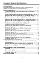
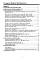
Compact Digital Multimeters
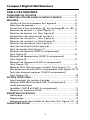
CONTENTS
SAFETY INFORMATION ........................................................... 2
SYMBOLS USED IN THIS MANUAL ........................................ 3
MAKING MEASUREMENTS ..................................................... 3
Verify Instrument Operation ..............................................3
Range Selection .................................................................. 4
Correcting an Overload (0o or -0o) Indication� .............. 4
Measuring DC Voltage (See Figure 1) ................................ 4
Measuring AC Voltage (See Figure 2) ................................ 5
Preparing for Current Measurements ............................... 5
Measuring DC Current (See Figure 3) ................................ 5
Measuring AC Current (See Figure 4) ................................ 6
Measuring Resistance (See Figure 5) ................................. 6
Testing for Continuity (See Figure 6) ................................. 7
Testing Diodes See (See Figure 7) ...................................... 7
Measuring Capacitance (35XP-A only) (See Figure 8) ....... 7
Measuring Temperature (35XP-A only) (See Figure 9) ..... 8
Measuring Frequency (35XP-A only) (See Figure 10) ........ 8
Measuring NCV (Non-Contact Voltage) (See Figure 11) ... 9
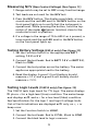
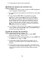
Testing Battery Voltage (5XP-A only) (See Figure 12) ......9
Testing Logic Levels (15XP-B only) (See Figure 13) ........... 9
ADDITIONAL FEATURES .......................................................... 9
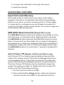
Input Test Lead Warning .................................................... 10
MIN MAX Measurements (Model 5XP-A only) ................. 10
Auto Power Off (Models 15XP-B and 35XP-A only) ........10
HOLD Measurements ......................................................... 11
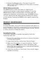
PRODUCT MAINTENANCE ...................................................... 11
Cleaning ............................................................................. 11
Troubleshooting ................................................................. 11
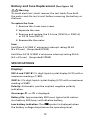
Battery and Fuse Replacement (See Figure 14) ................ 12
SPECIFICATIONS ...................................................................... 12

2
2A MAX
FUSED
COM A
200mA MAX
FUSED
BATT 1.5V
BATT 9V
VCOM mA
LOGIC
V
15XP-B
RANGE NON
CONTACT
VOLTAGE
HOLD
5XP-A
MIN MAX NON
CONTACT
VOLTAGE
HOLD
600600 200200
2020
22
200
m
200
m
200
2k
20k
200k
2M
20M
200m
20m
2m
200 A
VV
V
V
mA
A
A
auto-off
OFF
OFF
200
m
2m
20m
1.5V 9V
200
BATT
mA
A
A
35XP-A
15XP-A5XP-A
2A MAX
FUSED
COM A
Hz Temp
V
mA
2A
A
mA
400
1000
A
A
RANGE NON
CONTACT
VOLTAGE
HOLD
V
HZ
V
auto-off
°C
OFF
°F
mA
A
A
1832 400
35XP-A
CAT 600V
CAT 300V
600V
CAT CAT 600V
CAT 300V
MAX
600V
600V
MAX
600V
600V
MAX
600V
600V
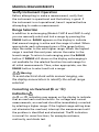
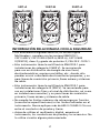
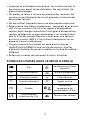
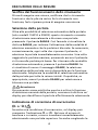
SAFETY INFORMATION
• The XP Series Digital Multimeters conform to EN61010-
1, CAT II 600 V, CAT III 300 V(5XP-A,35XP-A), CAT III 600
V(15XP-B), class 2 and pollution deg.2;
CSA 22.2 -1010-1.
• This instrument is EN61010-1 certied for Installation
Category II (600 V). It is recommended for use with local
level power distribution, appliances, portable equipment,
etc, where only smaller transient overvoltages may occur,
and not for primary supply lines, overhead lines and cable
systems.
• This instrument is EN61010-1 certied for Installation
Category III ( 300 V). It is recommended for use in
distribution level and fixed installations, as well as lesser
installations, and not for primary supply lines, overhead
lines and cable systems.
• Do not exceed the maximum overload limits per function
(see specifications) nor the limits marked on the instrument
itself. Never apply more than 600 V dc/600 V ac rms
between the test lead and earth ground.
• If the equipment is used in a manner not specified by the
manufacturer, the protection provided by the equipment
may be impaired.

3
• Inspect the DMM, test leads and accessories before every
use. Do not use any damaged part.
• Never ground yourself when taking measurements. Do not
touch exposed circuit elements or test probe tips.
• Do not operate the instrument in an explosive atmosphere.
• Exercise extreme caution when: measuring voltage >20 V
// current >10 mA // AC power line with inductive loads //
AC power line during electrical storms // current, when the
fuse blows in a circuit with open circuit voltage >600 V //
servicing CRT equipment.
• Always measure current in series with the load – NEVER
ACROSS a voltage source. Check fuse first. Never replace a
fuse with one of a different rating.
• Remove test leads before opening the case.
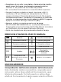
SYMBOLS USED IN THIS MANUAL
Battery �Refer to the manual
Double insulated Dangerous Voltage
Direct Current Earth Ground
Alternating Current Audible tone
IFuse )Canadian Standards
Association
PComplies with EU
directives Non-contact Voltage

4
MAKING MEASUREMENTS
Verify Instrument Operation
Before attempting to make a measurement, verify that
the instrument is operational and the battery is good. If
the instrument is not operational, have it repaired before
attempting to make a measurement.
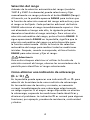
Range Selection
In addition to autoranging (Models 15XP-B and 35XP-A only)
you can manually select and lock a range by pressing the
RANGE button. RANGE appears on the display to indicate
that manual ranging is active and the range is locked. When
appropriate, each subsequent press of the range button
steps the meter to the next higher range. When the highest
range is reached the next press returns the meter to the
lowest range. To return to autoranging press the RANGE
button. If RANGE still shows on the display, autoranging is
not available for the selected function.Use autorange for
all initial measurements. Then, when appropriate, use the
RANGE button to select and lock a range.
�Warning
To avoid electrical shock while manual ranging, use
the display annunciators to identify the actual range
selected.
Correcting an Overload (0o or -0o)
Indication�
An 0o or -0o indication may appear on the display to indicate
that an overload condition exists. For voltage and current
measurements, an overload should be immediately corrected
by selecting a higher range. If the highest range setting does
not eliminate the overload, interrupt the measurement until
the problem is identified and eliminated. The 0o indication
is normal for some functions; for example,resistance,
continuity, and diode test.

5
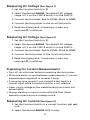
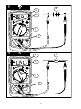
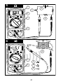
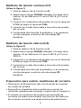
Measuring DC Voltage (See Figure 1)
1. Set the Function Switch to .
2. Select the desired RANGE. The default DC voltage
range is 2 V on the 15XP-B and 4 V on the 35XP-A.
3. Connect the test leads: Red to V , Black to COM.
4. Connect the test probes to the circuit test points.
5. Read the display, and, if necessary, correct any
overload (0o) conditions.
Measuring DC Voltage (See Figure 2)
1. Set the Function Switch to .
2. Select the desired RANGE. The default AC voltage
range is 2 V on the 15XP-B and 4 V on the 35XP-A.
3. Connect the test leads: Red to V , Black to COM.
4. Connect the test probes to the circuit test points.
5. Read the display, and, if necessary, correct any
overload (0o) conditions.
Preparing for Current Measurements
• Turn off circuit power before connecting the test probes.
• Allow the meter to cool between measurements, if current
measurements approach or exceeds 2 amps.
• A warning tone sounds if you connect a test lead to a
current input while a current function is not selected.
• Open circuit voltage at the measurement point must not
exceed 600V.
• Always measure current in series with the load. Never
measure current across a voltage source.
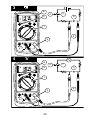
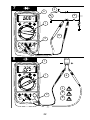
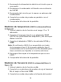
Measuring DC Current (See Figure 3)
1. Set the Function Switch to a current function, μA, mA,
or A.
2. Select the desired RANGE (5XP-A only).

6
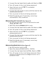
3. Connect the test leads: Red to mA or A, Black to COM.
4. Turn off power to the circuit being measured.
5. Open the test circuit (X) to establish
measurement points.
6. Connect the test probes in series with the load (to the
measurement points).
7. Turn on power to the circuit being measured.
8. Read the display, and, if necessary, correct any
overload (0o or -0o) conditions.
Measuring AC Current (See Figure 4)
1. Set the Function Switch to a current function and
range, μA, mA, or A.
2. Select the desired RANGE (5XP-A only).
3. Connect the test leads: Red to mA or A, Black to COM.
4. Turn off power to the circuit being measured.
5. Open the test circuit (X) to establish
measurement points.
6. Connect the test probes in series with the load (to the
measurement points).
7. Turn on power to the circuit being measured.
8. Read the display, and, if necessary, correct any
overload (0o) conditions.
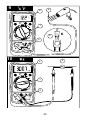
Measuring Resistance (See Figure 5)
1. Set the Function Switch to .
2. Select the desired RANGE (5XP-A, 15XP-B).
3. Connect the test leads: Red toV , Black to COM.
4. Turn off power to the circuit being measured. Never
measure resistance across a voltage source or on a
powered circuit.

7
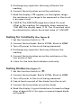
5. Discharge any capacitors that may influence the
reading.
6. Connect the test probes across the resistance.
7. Read the display. If 0o appears on the highest range,
the resistance is too large to be measured or the circuit
is an open circuit.
8. (15XP-B) The 2000 M range has a fixed 10-count
offset in the reading. For example, when measuring
1100 M, the display reads 1110. The 10 residual must
be subtracted to obtain the actual value of 1100 M
Testing for Continuity (See Figure 6)
1. Set the Function Switch to .
2. Connect the test leads: Red to V , Black to COM.
3. Turn off power to the circuit being measured.
4. Discharge any capacitors that may influence the
reading.
5. Connect the test probes across the resistance or the
two points of test.
6. Listen for the tone that indicates continuity.
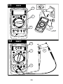
Testing Diodes (See Figure 7)
1. Set the Function Switch to .
2. Connect the test leads: Red to V , Black to COM.
3. Turn off power to the circuit being measured.
4. Free at least one end of the diode from the circuit.
5. Connect the test probes across the diode.
6. Read the display. A good diode has a forward voltage
drop of about 0.6 V. An open or reverse biased diode
will read 0o.

8
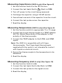
Measuring Capacitance (35XP-A only) (See Figure 8)
1. Set the Function Switch to the function.
2. Connect the test leads: Red to , Black to COM.
3. Turn off power to the circuit being measured.
4. Discharge the capacitor using a 100 k resistor.
5. Free at least one end of the capacitor from the circuit.
6. Connect the test probes across the capacitor.
7. Read the display.
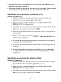
Measuring Temperature (35XP-A only) (See Figure 9)
1. Set the function switch to appropriate °C or °F range.
2. Connect the K-type thermocouple to a TEMP adapter
(XR-TA). Match the polarity of the adapter to the
polarity of the thermocouple.
3. Connect the TEMP adapter to the V and COM
inputs.
Note: The 35XP-A is compatible with all K-type
thermocouples. The K-type bead thermocouple
supplied with the meter is not intended for contact
with liquids or electrical circuits.
4. Expose the thermocouple to the temperature to be
measured.
5. Read the display.
Measuring Frequency (35XP-A only) (See Figure 10)
1. Set the Function Switch to Hz.
2. Connect the test leads: Red to Hz, Black to COM.
3. Connect the test probes to the signal source.
4. Read the display.

9
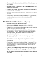
Measuring NCV (Non-Contact Voltage) (See Figure 11)
1. Range switch may be set to OFF or any function/range.
2. Test leads are not used for the NCV test.
3. Press the NCV button. The display goes blank, a tone
sounds and the red LED next to the NCV button on the
front panel lights up to verify that the instrument is
operational. While pressing the button, hold the top-
center of the meter (sensor location) close to the
conductor/circuit in question.
4. If a voltage in the range of 70 to 600 V ac is present, a
tone sounds and the red LED next to the NCV button
on the front panel lights up.
Testing Battery Voltage (5XP-A only) (See Figure 12)
1. Set the Function Switch to the appropriate BATT
setting, 1.5 V or 9 V.
2. Connect the test leads: Red to BATT 1.5 V or BATT 9 V,
Black to COM.
3. Connect the test probes across the battery. The meter
applies an appropriate load to the battery.
4. Read the display. A good 1.5 volt battery should
measure >1.2 V, and a good 9 volt battery should
measure > 7.2 V.
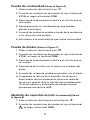
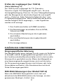
Testing Logic Levels (15XP-B only) (See Figure 13)
The 15XP-B tests logic levels for TTL logic. The meter displays
0o plus a ∧ for a high-level (true) condition. The meter beeps
and displays an 0o and a ∨ for a low-level (false) condition.
See Specifications for the logic 1 and logic 0 voltage limits.
Out-of-limits indications are displayed as 0o only, no ∧, ∨ or
beep occur.
1. Set the Function Switch to LOGIC.
2. Connect the test leads: Red to V , Black to COM.
3. Connect the black lead to logic common.

10
4. Connect the red lead to the logic test point.
5. Read the display.
ADDITIONAL FEATURES
Input Test Lead Warning
The meter emits a continuous tone when a test lead is
placed in the mA or A input jack and the Function/Range
Switch is not set to a correct current position. (If the meter
is connected to a voltage source with leads connected for
current, very high current could result). All current ranges are
protected by fast acting fuses.
MIN MAX Measurements (Model 5XP-A only)
The MIN MAX feature reads and updates the display to show
the maximum or minimum value measured after you press
the MIN MAX button.Pressing the MIN MAX button for less
than 1 second will put the meter into a mode of displaying
the maximum or minimum readings. Each time the button is
pressed,the meter will cycle to the next display mode. Press
the MIN MAX button for more than 1 second to disable this
feature.
Auto Power Off (Models 15XP-B and 35XP-A only)
Auto Power Off is a battery saving feature that puts the
meter into a sleep mode if the Function/Range Switch has
not changed position in the last 10 minutes. To wake the
meter turn the Function/Range Switch to another position.
The Auto Power Off feature can be disabled to keep the
meter from going to sleep.To disable the Auto Power Off
feature use the following procedure:
1. Set the Function Switch to OFF.
2. Press and hold the Range button while turning the
Function Switch from OFF to the desired function.

11
3. Release the Range button. The Auto Power Off
feature will remain disabled until the meter is turned
off and then on.
HOLD Measurements
The HOLD button causes the meter to capture and
continuously display a measurement reading. To use the
HOLD feature make a measurement, and then,after the
reading has stabilized, momentarily press the HOLD button.
You can remove the test leads and the reading will remain
on the display. Pressing the HOLD button again releases the
display.
PRODUCT MAINTENANCE
Cleaning
To clean the meter, use a soft cloth moistened with water. To
avoid damage to the plastic components do not use benzene,
alcohol, acetone, ether, paint thinner,lacquer thinner, ketone
or other solvents to clean the meter.
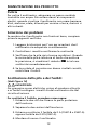
Troubleshooting
If the meter appears to operate improperly, check the
following items first.
1. Review the operating instructions to ensure the meter
is being used properly.
2. Inspect and test the continuity of the test leads.
3. Make sure the battery is in good condition. The low
battery symbol appears when the battery falls
below the level where accuracy is guaranteed.Replace
a low-battery immediately.
4. Check the condition of the fuses if the current ranges
operate incorrectly.

12
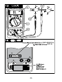
Battery and Fuse Replacement (See Figure 14)
�Warning
To avoid electrical, shock remove the test leads from both
the meter and the test circuit before accessing the battery or
thefuses.
To replace the fuse:
1. Remove the 2 rear-case screws.
2. Separate the case.
3. Remove and replace the 2 A fuse (15XP-B or 35XP-A)
or 0.315 fuse (5XP-A).
4. Reassemble the meter.
Fuse:
Fast Blow 2 A/1000 V, minimum interrupt rating 30 kA
(6 x 32 mm) (Amprobe® FP200).
Fast Blow 0.315 A/1000 V minimum interrupt rating 30 kA
(6.3 x 32 mm) (Amprobe® FP300)
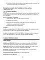
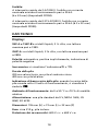
SPECIFICATIONS
Display:
5XP-A and 15XP-B:3 ½ digit liquid crystal display (LCD) with a
maximum reading of 1999.
35XP-A: 3 ¾ digit liquid crystal display (LCD) with a maximum
reading of 3999.
Polarity: Automatic, positive implied, negative polarity
indication.
Overrange: 0o or -0o is displayed.
Battery life: Approximately 200 hours typical with carbon-
zinc battery. 400 hours with alkaline battery.
Low battery indication: The symbol is displayed when
the battery voltage drops below the operating level.

13
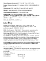
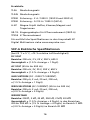
Operating environment: 0 °C to 50 °C at <70 % R.H.
Power: Single standard 9 V battery, NEDA 1604, JIS 006P, IEC
6F22.
Dimensions: 155 mm (H) ×72 mm (W) ×32 mm (D)
Weight: Approximately 210 g including battery.
Overload protection: 600 V dc or 600 V ac
Accessories: One pair test leads TL245, 9 V battery
(installed),holster, magnet strap, Users Manual, Type K Bead
Thermocouple (35XP-A only), and temperature adaptor
(35XP-A only).
Altitude: 6561.7 Feet (2000 m)
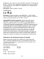
P )
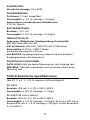
Safety: Conforms to EN61010-1, CAT II 600V, CAT III
300V(5XP-A,35XP-A), CAT III 600 V(15XP-B), class 2 and
pollution deg. 2; CSA 22.2 -1010-1.
EMC: Conforms to EN61326-1. This product complies with
requirements of the following European Community
Directives: 89/ 336/ EEC (Electromagnetic Compatibility) and
73/ 23/ EEC (Low Voltage) as amended by
93/ 68/EEC(CE Marking). However, electrical noise or intense
electromagnetic fields in the vicinity of the equipment may
disturb the measurement circuit. Measuring instruments
will also respond to unwanted signals that may be present
within the measurement circuit. Users should exercise care
and take appropriate precautions to avoid misleading results
when making measurements in the presence of electronic
interference.
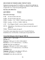
Non-Contact Voltage Indicator
Sense voltage 70 V to 600 VAC (50 Hz to 60 Hz) beeper chirps
and bright red LED comes on, works when meter dial is on
any range.
Detection Distance
115 V 60 Hz 22 mm (1 in)
230 V 50 Hz 75 mm (3 in)
La page est en cours de chargement...
La page est en cours de chargement...
La page est en cours de chargement...
La page est en cours de chargement...
La page est en cours de chargement...
La page est en cours de chargement...
La page est en cours de chargement...
La page est en cours de chargement...
La page est en cours de chargement...
La page est en cours de chargement...
La page est en cours de chargement...
La page est en cours de chargement...
La page est en cours de chargement...
La page est en cours de chargement...
La page est en cours de chargement...
La page est en cours de chargement...
La page est en cours de chargement...
La page est en cours de chargement...
La page est en cours de chargement...
La page est en cours de chargement...
La page est en cours de chargement...
La page est en cours de chargement...
La page est en cours de chargement...
La page est en cours de chargement...
La page est en cours de chargement...
La page est en cours de chargement...
La page est en cours de chargement...
La page est en cours de chargement...
La page est en cours de chargement...
La page est en cours de chargement...
La page est en cours de chargement...
La page est en cours de chargement...
La page est en cours de chargement...
La page est en cours de chargement...
La page est en cours de chargement...
La page est en cours de chargement...
La page est en cours de chargement...
La page est en cours de chargement...
La page est en cours de chargement...
La page est en cours de chargement...
La page est en cours de chargement...
La page est en cours de chargement...
La page est en cours de chargement...
La page est en cours de chargement...
La page est en cours de chargement...
La page est en cours de chargement...
La page est en cours de chargement...
La page est en cours de chargement...
La page est en cours de chargement...
La page est en cours de chargement...
La page est en cours de chargement...
La page est en cours de chargement...
La page est en cours de chargement...
La page est en cours de chargement...
La page est en cours de chargement...
La page est en cours de chargement...
La page est en cours de chargement...
La page est en cours de chargement...
La page est en cours de chargement...
La page est en cours de chargement...
La page est en cours de chargement...
La page est en cours de chargement...
La page est en cours de chargement...
La page est en cours de chargement...
La page est en cours de chargement...
La page est en cours de chargement...
La page est en cours de chargement...
La page est en cours de chargement...
La page est en cours de chargement...
La page est en cours de chargement...
La page est en cours de chargement...
La page est en cours de chargement...
La page est en cours de chargement...
La page est en cours de chargement...
La page est en cours de chargement...
La page est en cours de chargement...
La page est en cours de chargement...
La page est en cours de chargement...
La page est en cours de chargement...
La page est en cours de chargement...
La page est en cours de chargement...
La page est en cours de chargement...
La page est en cours de chargement...
La page est en cours de chargement...
La page est en cours de chargement...
La page est en cours de chargement...
La page est en cours de chargement...
La page est en cours de chargement...
La page est en cours de chargement...
La page est en cours de chargement...
La page est en cours de chargement...
La page est en cours de chargement...
La page est en cours de chargement...
La page est en cours de chargement...
La page est en cours de chargement...
La page est en cours de chargement...
La page est en cours de chargement...
La page est en cours de chargement...
La page est en cours de chargement...
La page est en cours de chargement...
La page est en cours de chargement...
La page est en cours de chargement...
La page est en cours de chargement...
La page est en cours de chargement...
La page est en cours de chargement...
La page est en cours de chargement...
-
 1
1
-
 2
2
-
 3
3
-
 4
4
-
 5
5
-
 6
6
-
 7
7
-
 8
8
-
 9
9
-
 10
10
-
 11
11
-
 12
12
-
 13
13
-
 14
14
-
 15
15
-
 16
16
-
 17
17
-
 18
18
-
 19
19
-
 20
20
-
 21
21
-
 22
22
-
 23
23
-
 24
24
-
 25
25
-
 26
26
-
 27
27
-
 28
28
-
 29
29
-
 30
30
-
 31
31
-
 32
32
-
 33
33
-
 34
34
-
 35
35
-
 36
36
-
 37
37
-
 38
38
-
 39
39
-
 40
40
-
 41
41
-
 42
42
-
 43
43
-
 44
44
-
 45
45
-
 46
46
-
 47
47
-
 48
48
-
 49
49
-
 50
50
-
 51
51
-
 52
52
-
 53
53
-
 54
54
-
 55
55
-
 56
56
-
 57
57
-
 58
58
-
 59
59
-
 60
60
-
 61
61
-
 62
62
-
 63
63
-
 64
64
-
 65
65
-
 66
66
-
 67
67
-
 68
68
-
 69
69
-
 70
70
-
 71
71
-
 72
72
-
 73
73
-
 74
74
-
 75
75
-
 76
76
-
 77
77
-
 78
78
-
 79
79
-
 80
80
-
 81
81
-
 82
82
-
 83
83
-
 84
84
-
 85
85
-
 86
86
-
 87
87
-
 88
88
-
 89
89
-
 90
90
-
 91
91
-
 92
92
-
 93
93
-
 94
94
-
 95
95
-
 96
96
-
 97
97
-
 98
98
-
 99
99
-
 100
100
-
 101
101
-
 102
102
-
 103
103
-
 104
104
-
 105
105
-
 106
106
-
 107
107
-
 108
108
-
 109
109
-
 110
110
-
 111
111
-
 112
112
-
 113
113
-
 114
114
-
 115
115
-
 116
116
-
 117
117
-
 118
118
-
 119
119
-
 120
120
-
 121
121
-
 122
122
-
 123
123
-
 124
124
-
 125
125
-
 126
126


Amprobe AM-35XPA Le manuel du propriétaire
- Catégorie
- Mesure, test
- Taper
- Le manuel du propriétaire
dans d''autres langues
- italiano: Amprobe AM-35XPA Manuale del proprietario
- español: Amprobe AM-35XPA El manual del propietario
- Deutsch: Amprobe AM-35XPA Bedienungsanleitung
Documents connexes
-
Amprobe C Le manuel du propriétaire
-
-
-
-
Amprobe AM-AC75B Manuel utilisateur
-
-
-
-
-


